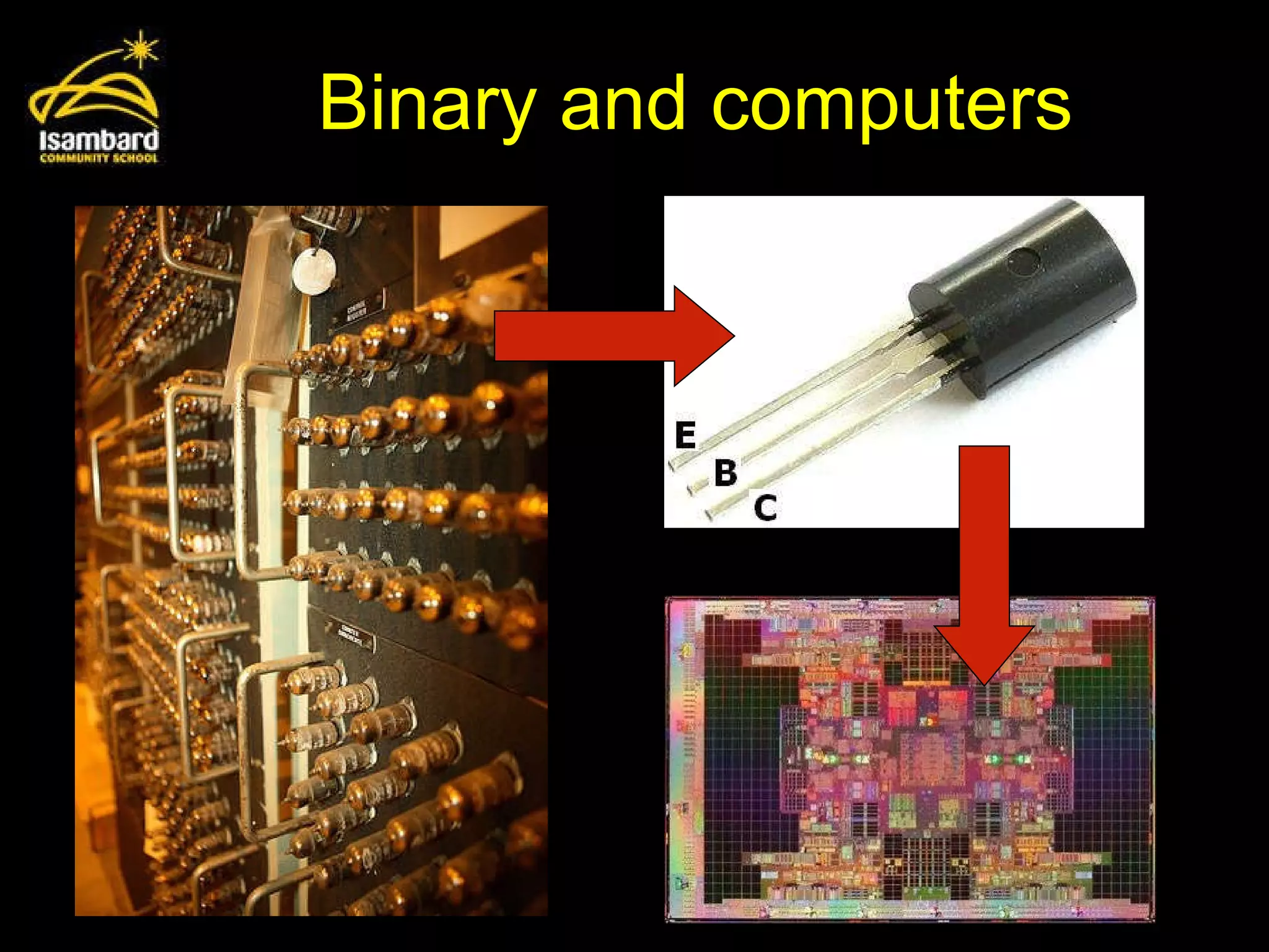
This document discusses binary logic and how logic gates work in computing. It introduces the logic gates NOT, AND, and OR and how their inputs affect their outputs. It provides examples of logic diagrams and truth tables. It also presents a scenario of a car warning system and challenges the reader to represent the system with logic gates and a truth table.
You need tobe able to: explain why data is represented in computer systems in binary form understand and produce simple logic diagrams using the operations NOT, AND and OR produce a truth table from a given logic diagram.
5.
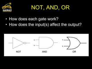
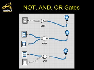
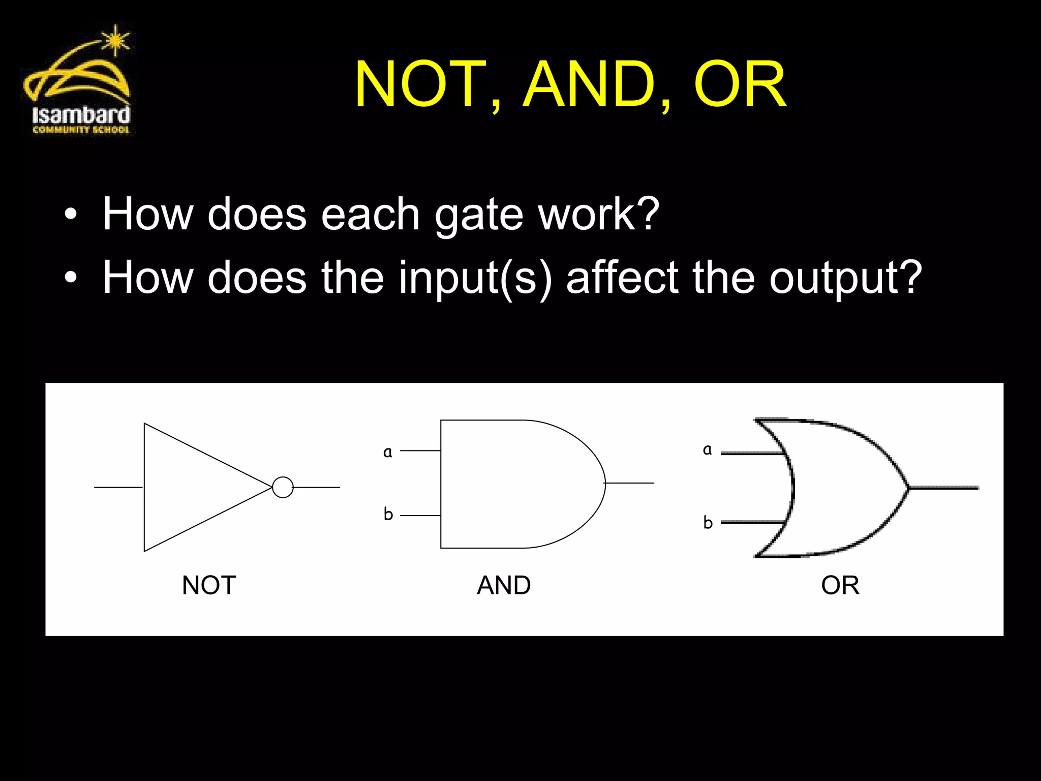
NOT, AND, ORHow does each gate work? How does the input(s) affect the output? a b a b NOT AND OR
Logic Diagram ActivityWithout using the computer … complete the truth table for diagrams 1 to 3 on your worksheet.
9.
Logic Diagram ActivityCheck your answers by using the logicly website to re-create the logic diagrams. http://logic.ly/demo
10.
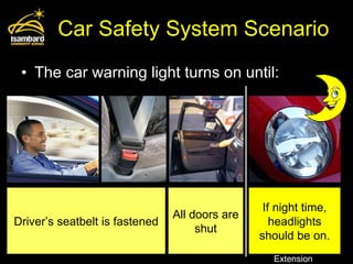
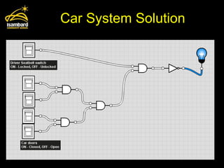
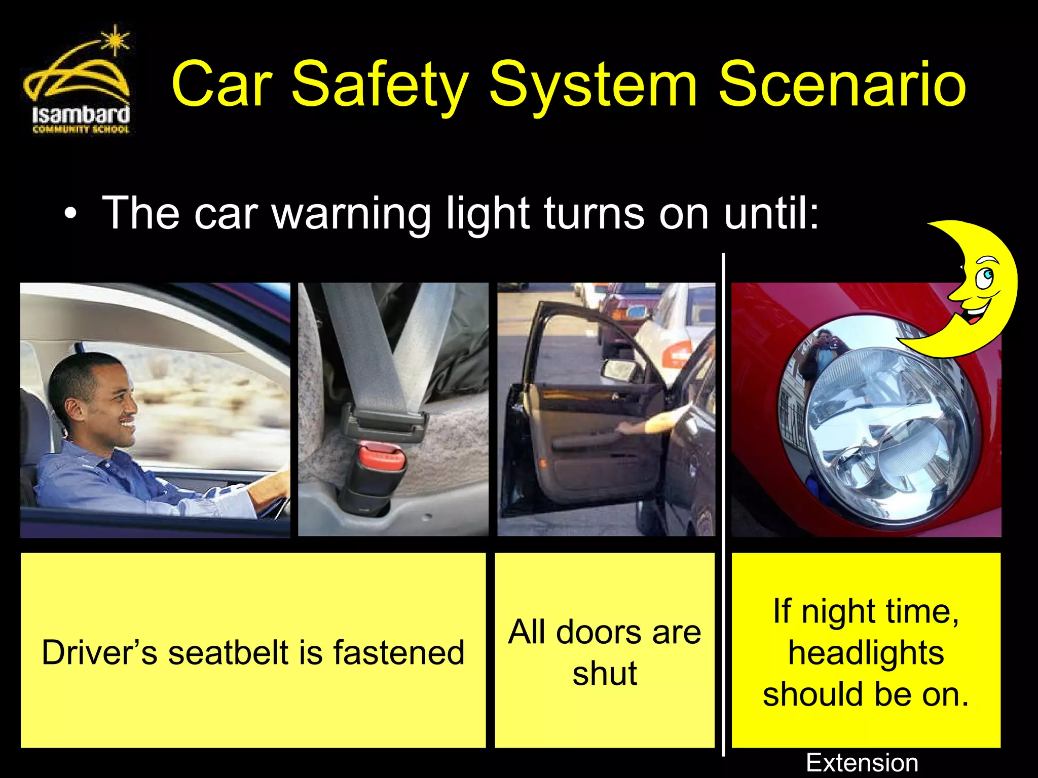
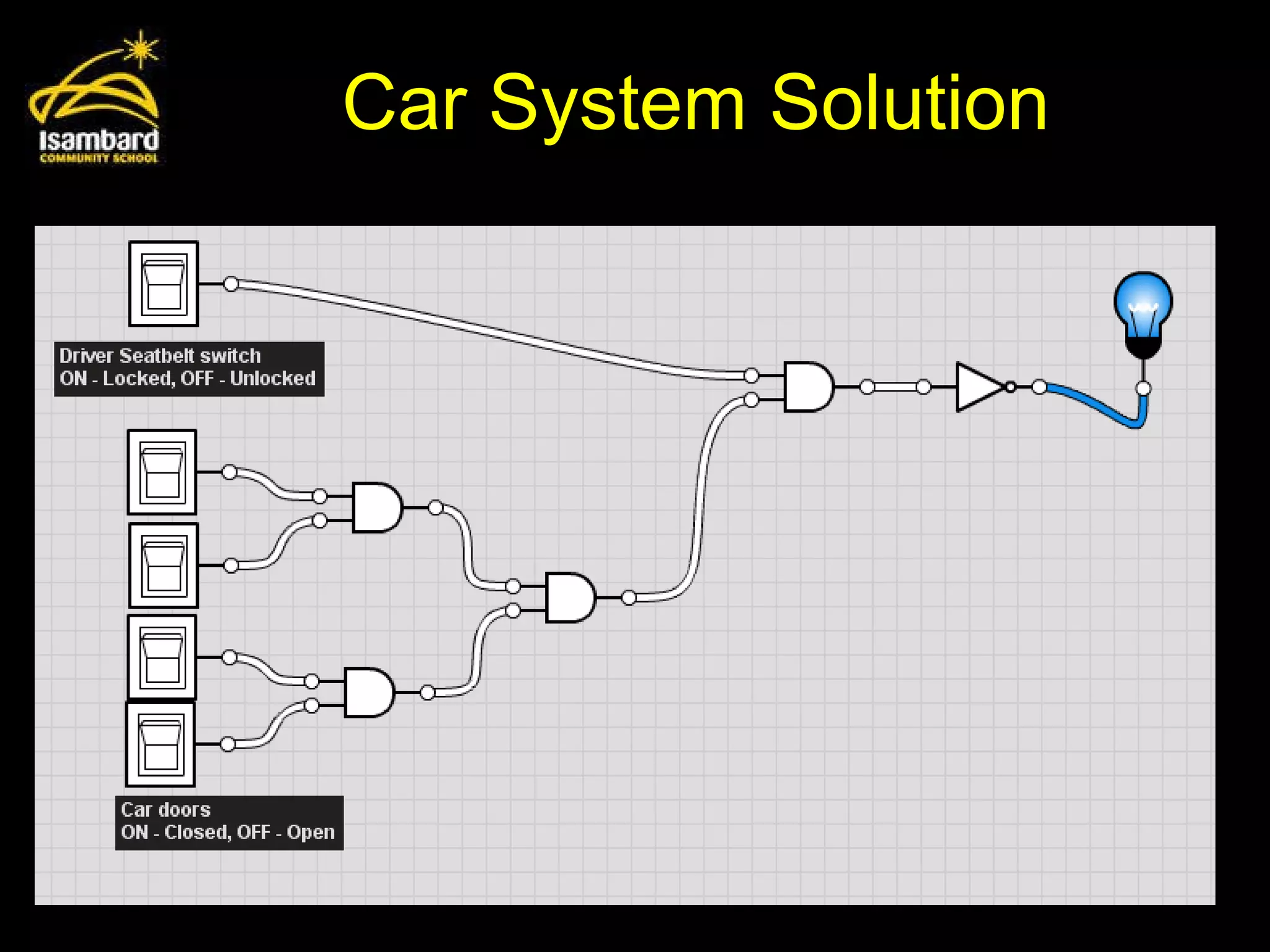
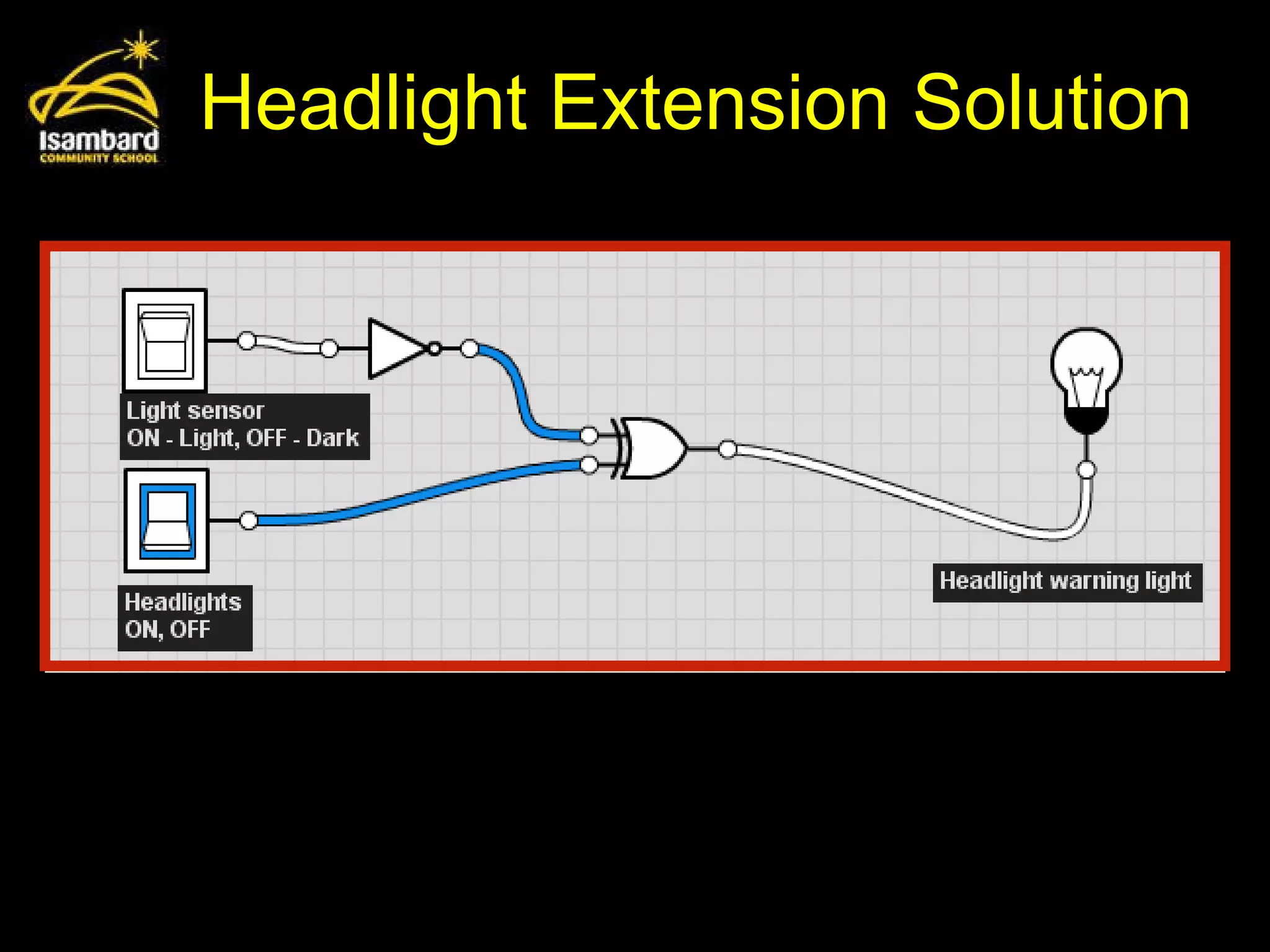
Car Safety SystemScenario The car warning light turns on until: Driver’s seatbelt is fastened All doors are shut If night time, headlights should be on. Extension
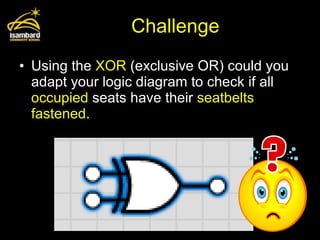
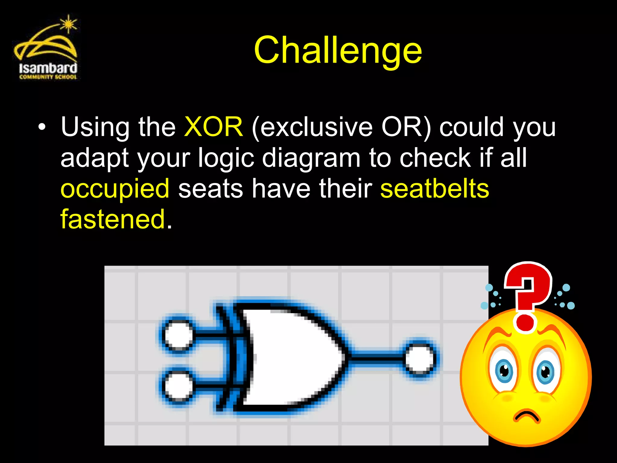
Challenge Using the XOR (exclusive OR) could you adapt your logic diagram to check if all occupied seats have their seatbelts fastened .
14.
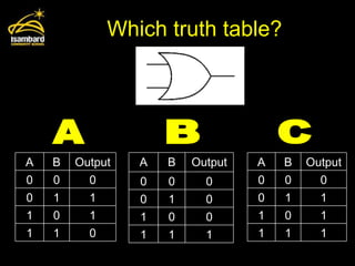
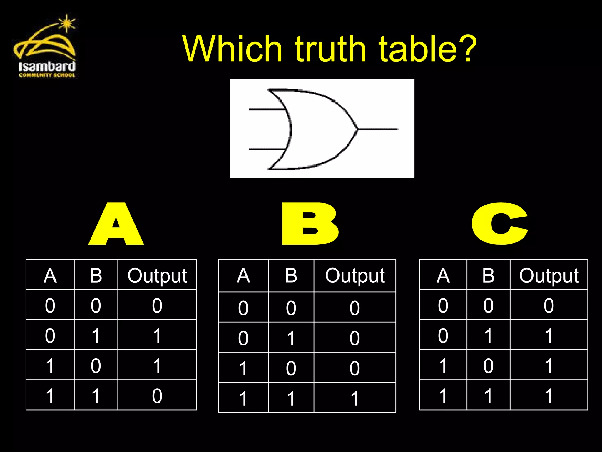
Which truth table?A B C A B Output 0 0 0 0 1 1 1 0 1 1 1 0 A B Output 0 0 0 0 1 1 1 0 1 1 1 1 A B Output 0 0 0 0 1 0 1 0 0 1 1 1
15.
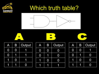
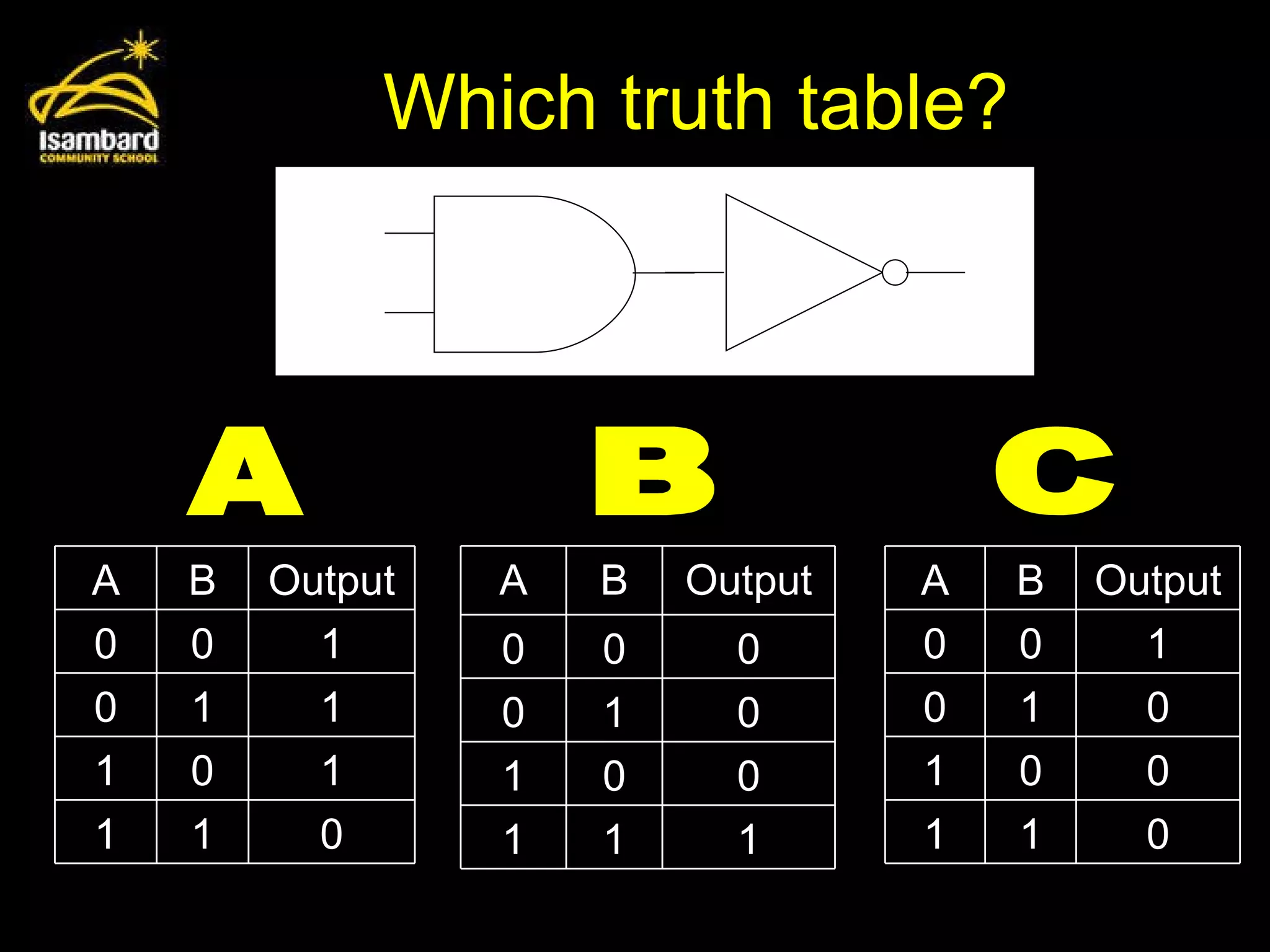
Which truth table?A B C A B Output 0 0 1 0 1 1 1 0 1 1 1 0 A B Output 0 0 1 0 1 0 1 0 0 1 1 0 A B Output 0 0 0 0 1 0 1 0 0 1 1 1
16.
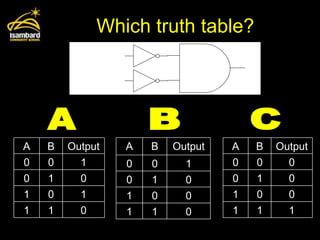
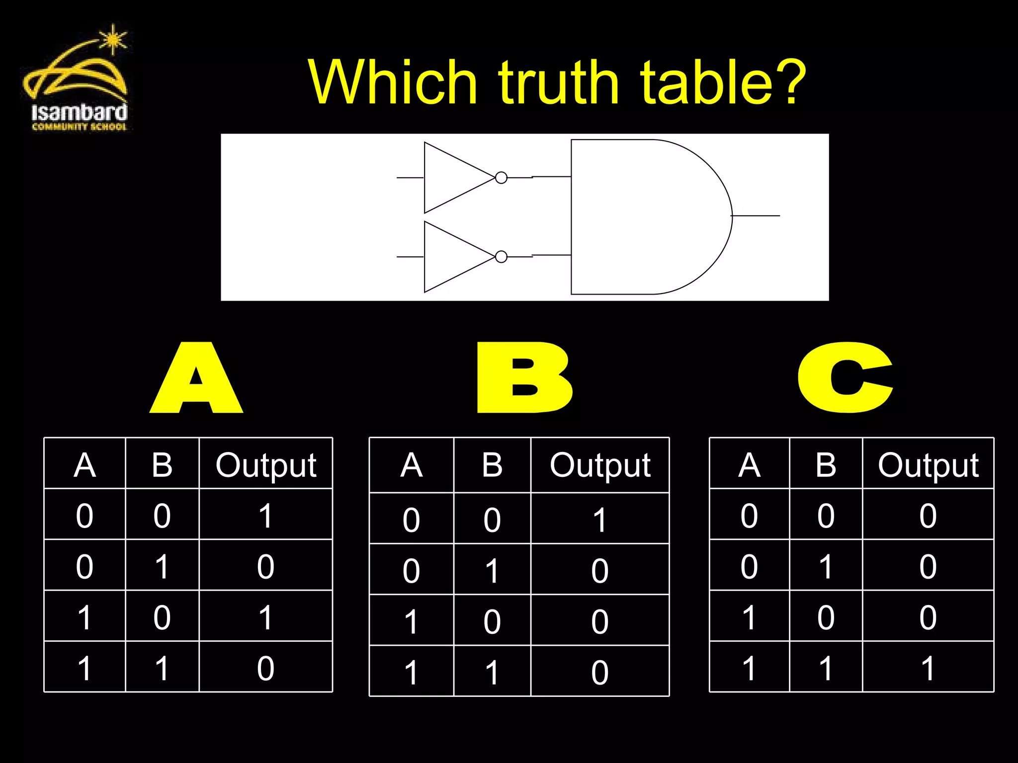
Which truth table?A B C A B Output 0 0 1 0 1 0 1 0 1 1 1 0 A B Output 0 0 0 0 1 0 1 0 0 1 1 1 A B Output 0 0 1 0 1 0 1 0 0 1 1 0
17.
Recap – canyou: explain why data is represented in computer systems in binary form understand and produce simple logic diagrams using the operations NOT, AND and OR produce a truth table from a given logic diagram.