The document provides an overview of 8051 microcontrollers, including:
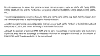
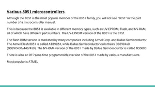
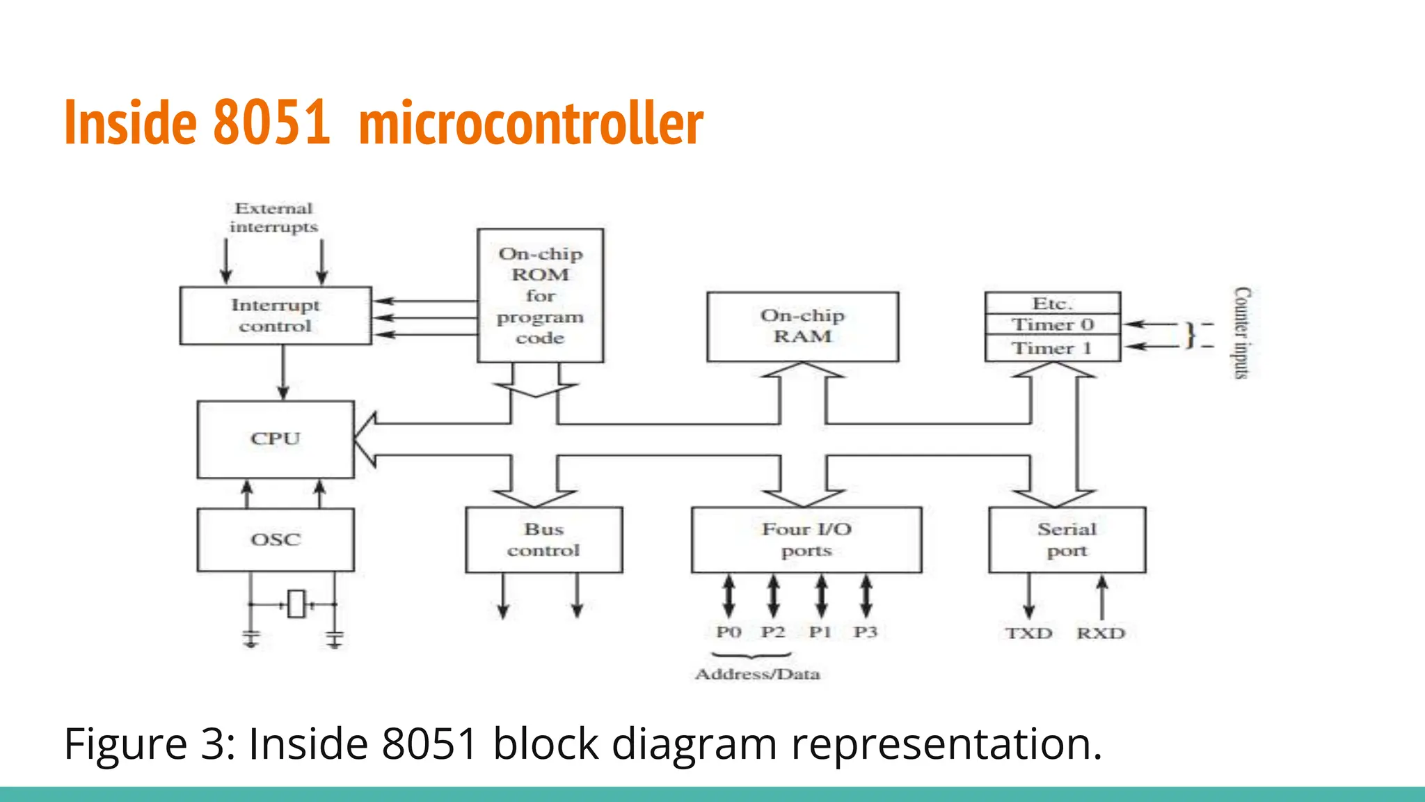
- The 8051 was introduced in 1981 as an early 8-bit microcontroller with RAM, ROM, I/O ports, and timers on a single chip.
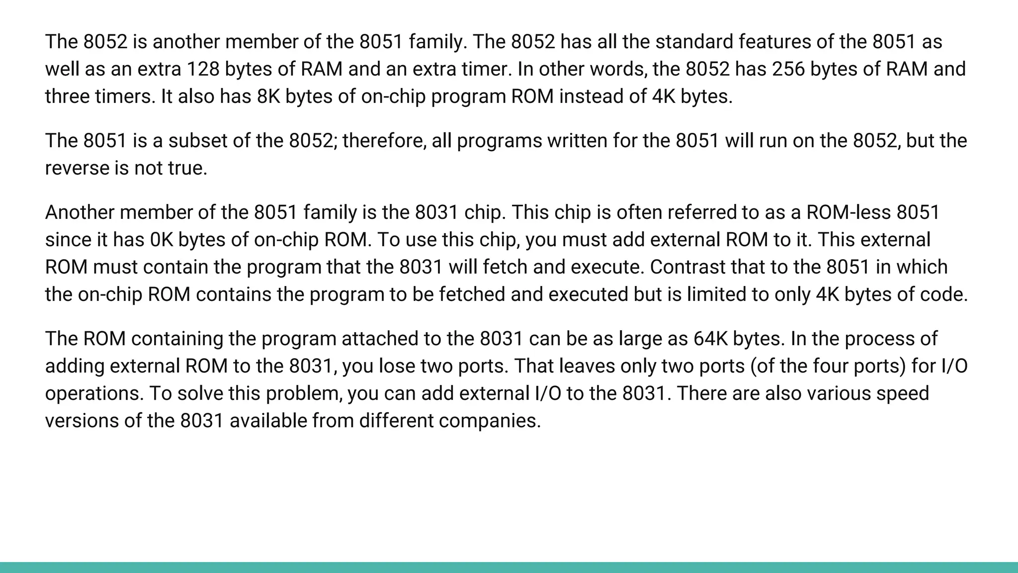
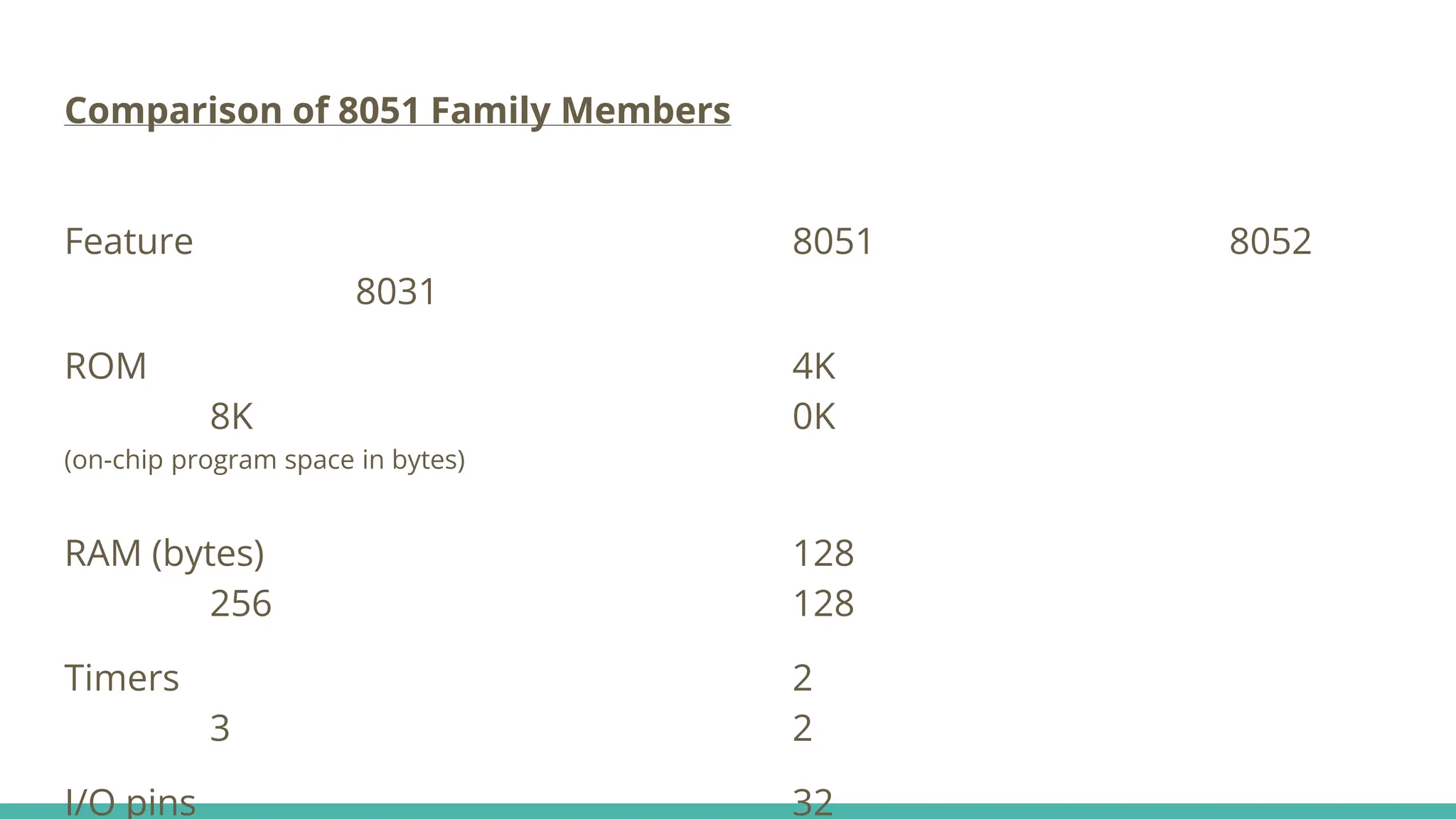
- It became widely popular after other manufacturers were allowed to produce compatible versions. Major 8051 family members include the 8051, 8052, and 8031.
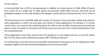
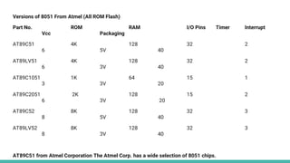
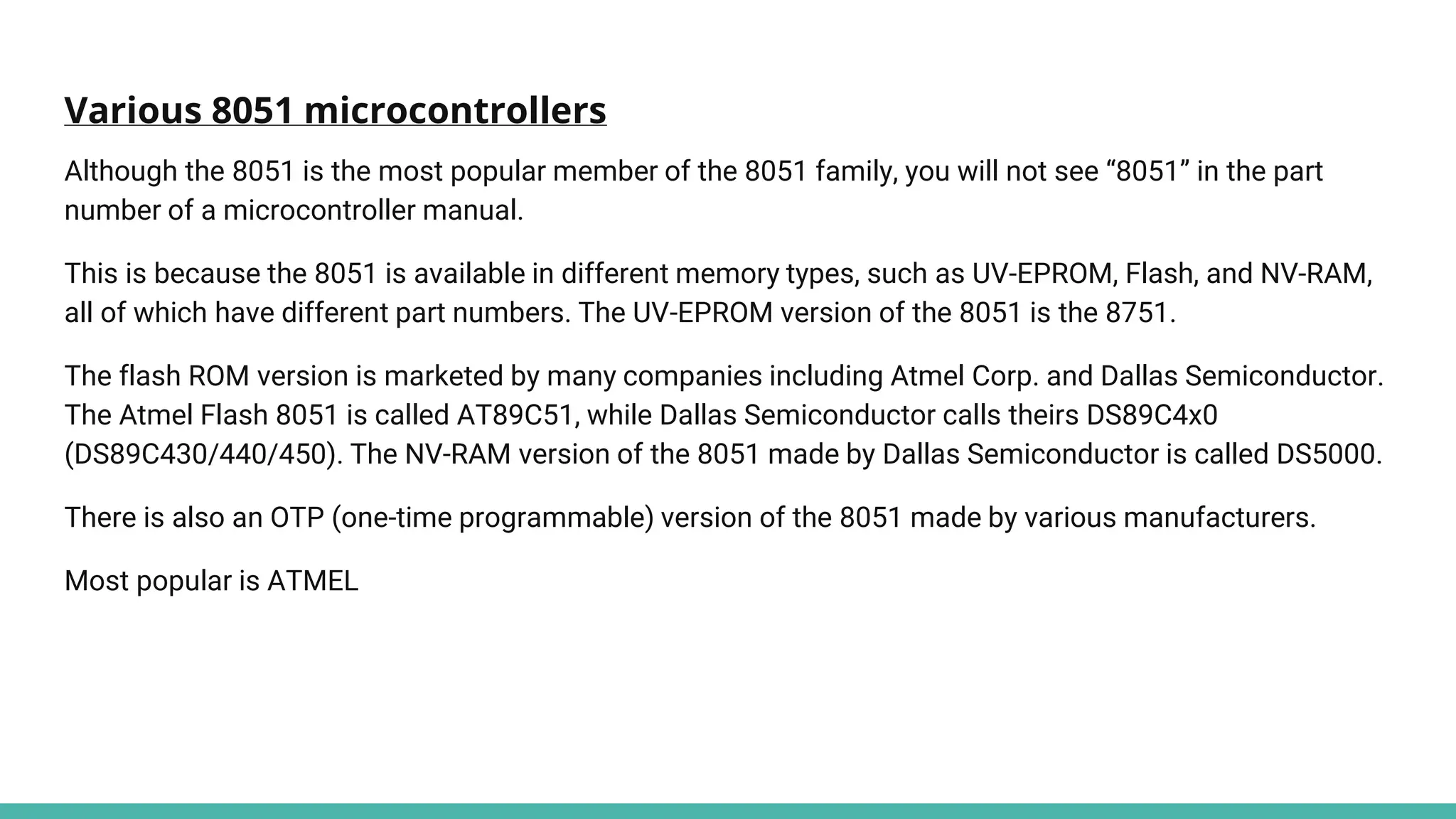
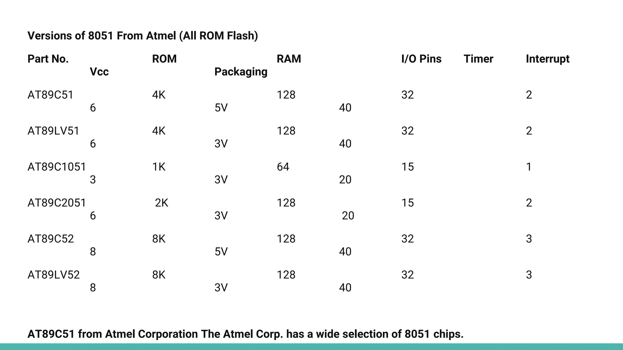
- The 8051 has 4K ROM, 128 bytes RAM, 4 I/O ports, and 2 timers. Variations were made with different memory types and capacities.
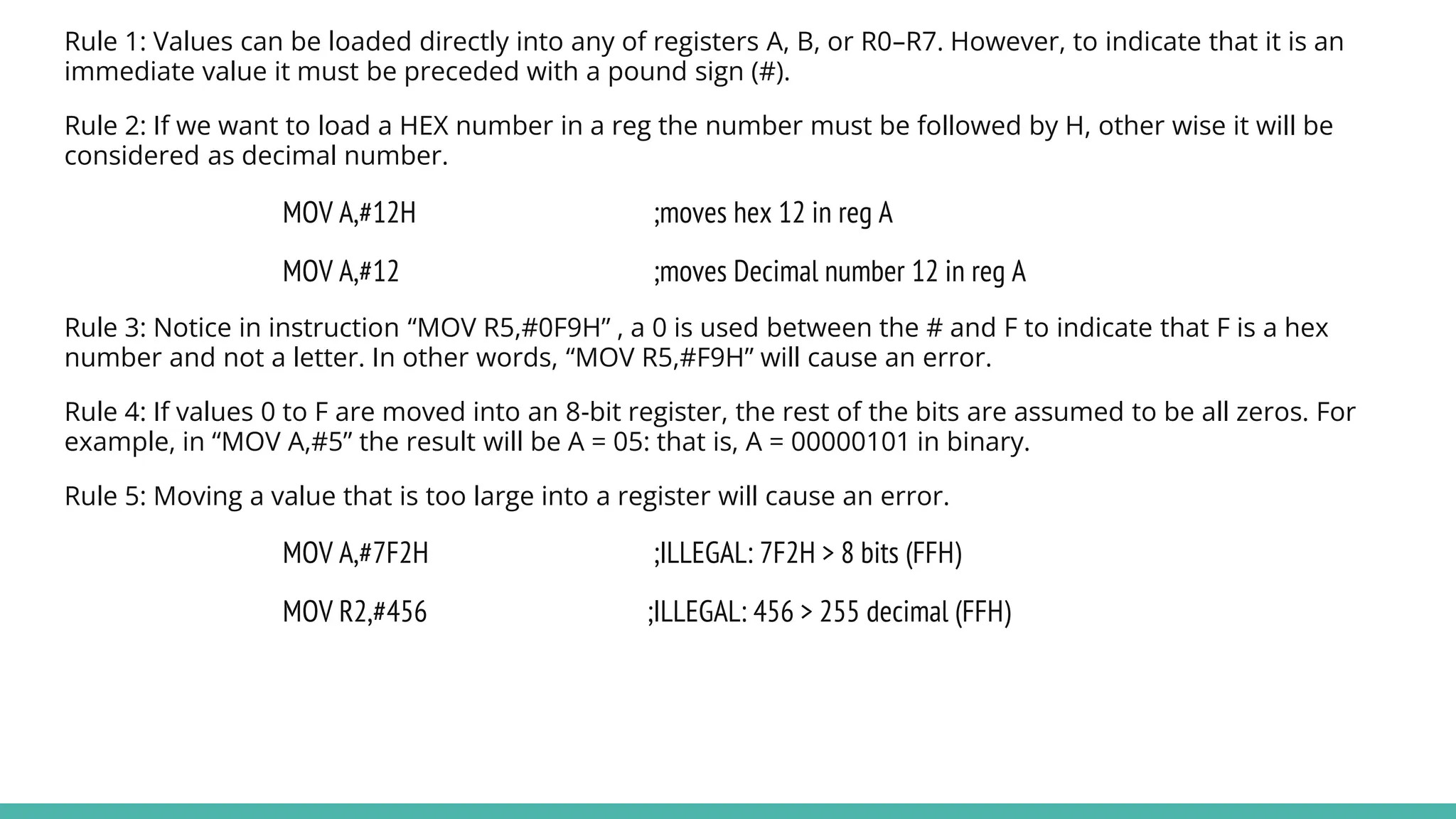
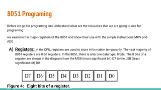
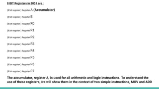
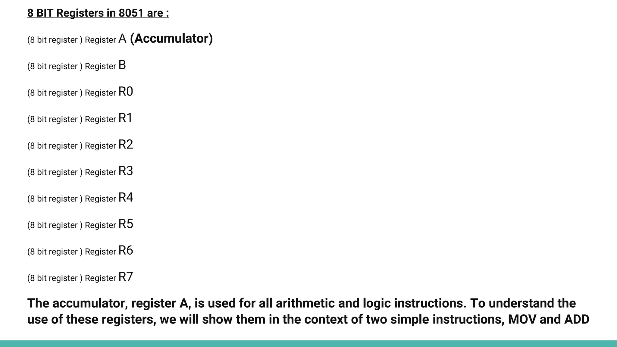
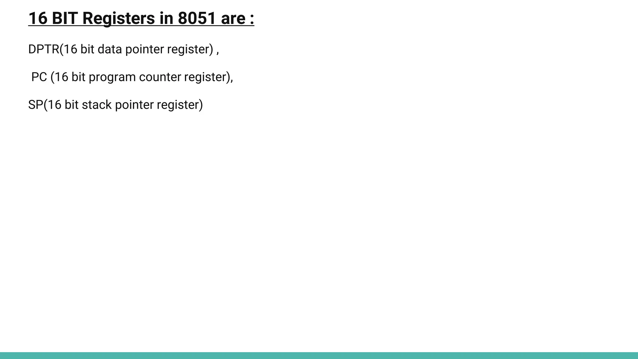
- Programming the 8051 involves understanding its registers for temporary data storage and basic instructions like MOV and ADD.
![What is a Microprocessor?
Computer's Central Processing Unit (CPU) built on a single Integrated Circuit (IC) is called a
microprocessor.
It is a programmable, multipurpose, clock -driven, register-based electronic device that reads binary
instructions from a storage device called memory, accepts binary data as input and processes data
according to those instructions and provides results as output.
A microprocessor consists of an ALU, control unit and register array. Where ALU performs arithmetic
and logical operations on the data received from an input device or memory. Control unit controls the
instructions and flow of data within the computer. And, register array consists of registers identified by
different names and addresses.
The microprocessor is made from millions of tiny components like transistors, registers, and diodes that
work together.[1]](https://image.slidesharecdn.com/8051microcontrollerprograming-240305130834-5f2d14eb/85/btech-8051-Microcontroller-Programing-pptx-2-320.jpg)
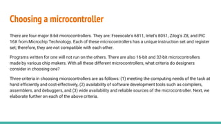
![Block Diagram of a General Purpose Microprocessor
Figure 1: General purpose Microprocessor. [2]](https://image.slidesharecdn.com/8051microcontrollerprograming-240305130834-5f2d14eb/85/btech-8051-Microcontroller-Programing-pptx-3-320.jpg)
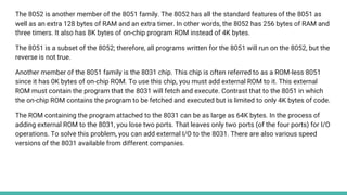
![What is the difference between a microprocessor and
microcontroller?
Figure 2: a. Microprocessor b. Microcontroller. [2]](https://image.slidesharecdn.com/8051microcontrollerprograming-240305130834-5f2d14eb/85/btech-8051-Microcontroller-Programing-pptx-4-320.jpg)


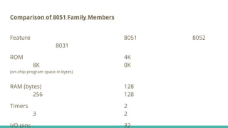

![Writing the first program:
An Assembly language instruction consists of four fields:
[label:] [mnemonic] [operands] [;comment]
Note: Label part is optional generally we see instructions as:
MOV destination,source ;copy source to dest.
NOTE: This instruction tells the CPU to move (in reality, copy) the source operand to the destination operand. For example, the instruction “MOV A,R0” copies the contents of register R0 to register A. After this instruction is executed,
register A will have the same value as register R0. The MOV instruction does not affect the source operand.
—------------------------------------------Playing with the MOV instruction ------------------------------------------------------------------------------------
MOV A,#55H ;load value 55H into reg. A
MOV R0,A ;copy contents of A into R0 ;(now A=R0=55H)
MOV R1,A ;copy contents of A into R1 ;(now A=R0=R1=55H)
MOV R2,A ;copy contents of A into R2 ;now A=R0=R1=R2=55H)
MOV R3,#95H ;load value 95H into R3 ;(now R3=95H)
MOV A,R3 ;copy contents of R3 into A ;now A=R3=95H)
MOV R5,#0F9H ;load F9H into R5 (R5=F9H)](https://image.slidesharecdn.com/8051microcontrollerprograming-240305130834-5f2d14eb/85/btech-8051-Microcontroller-Programing-pptx-19-320.jpg)


![What is a Microprocessor?
Computer's Central Processing Unit (CPU) built on a single Integrated Circuit (IC) is called a
microprocessor.
It is a programmable, multipurpose, clock -driven, register-based electronic device that reads binary
instructions from a storage device called memory, accepts binary data as input and processes data
according to those instructions and provides results as output.
A microprocessor consists of an ALU, control unit and register array. Where ALU performs arithmetic
and logical operations on the data received from an input device or memory. Control unit controls the
instructions and flow of data within the computer. And, register array consists of registers identified by
different names and addresses.
The microprocessor is made from millions of tiny components like transistors, registers, and diodes that
work together.[1]](https://image.slidesharecdn.com/8051microcontrollerprograming-240305130834-5f2d14eb/75/btech-8051-Microcontroller-Programing-pptx-2-2048.jpg)
![Block Diagram of a General Purpose Microprocessor
Figure 1: General purpose Microprocessor. [2]](https://image.slidesharecdn.com/8051microcontrollerprograming-240305130834-5f2d14eb/75/btech-8051-Microcontroller-Programing-pptx-3-2048.jpg)
![What is the difference between a microprocessor and
microcontroller?
Figure 2: a. Microprocessor b. Microcontroller. [2]](https://image.slidesharecdn.com/8051microcontrollerprograming-240305130834-5f2d14eb/75/btech-8051-Microcontroller-Programing-pptx-4-2048.jpg)

![Writing the first program:
An Assembly language instruction consists of four fields:
[label:] [mnemonic] [operands] [;comment]
Note: Label part is optional generally we see instructions as:
MOV destination,source ;copy source to dest.
NOTE: This instruction tells the CPU to move (in reality, copy) the source operand to the destination operand. For example, the instruction “MOV A,R0” copies the contents of register R0 to register A. After this instruction is executed,
register A will have the same value as register R0. The MOV instruction does not affect the source operand.
—------------------------------------------Playing with the MOV instruction ------------------------------------------------------------------------------------
MOV A,#55H ;load value 55H into reg. A
MOV R0,A ;copy contents of A into R0 ;(now A=R0=55H)
MOV R1,A ;copy contents of A into R1 ;(now A=R0=R1=55H)
MOV R2,A ;copy contents of A into R2 ;now A=R0=R1=R2=55H)
MOV R3,#95H ;load value 95H into R3 ;(now R3=95H)
MOV A,R3 ;copy contents of R3 into A ;now A=R3=95H)
MOV R5,#0F9H ;load F9H into R5 (R5=F9H)](https://image.slidesharecdn.com/8051microcontrollerprograming-240305130834-5f2d14eb/75/btech-8051-Microcontroller-Programing-pptx-19-2048.jpg)