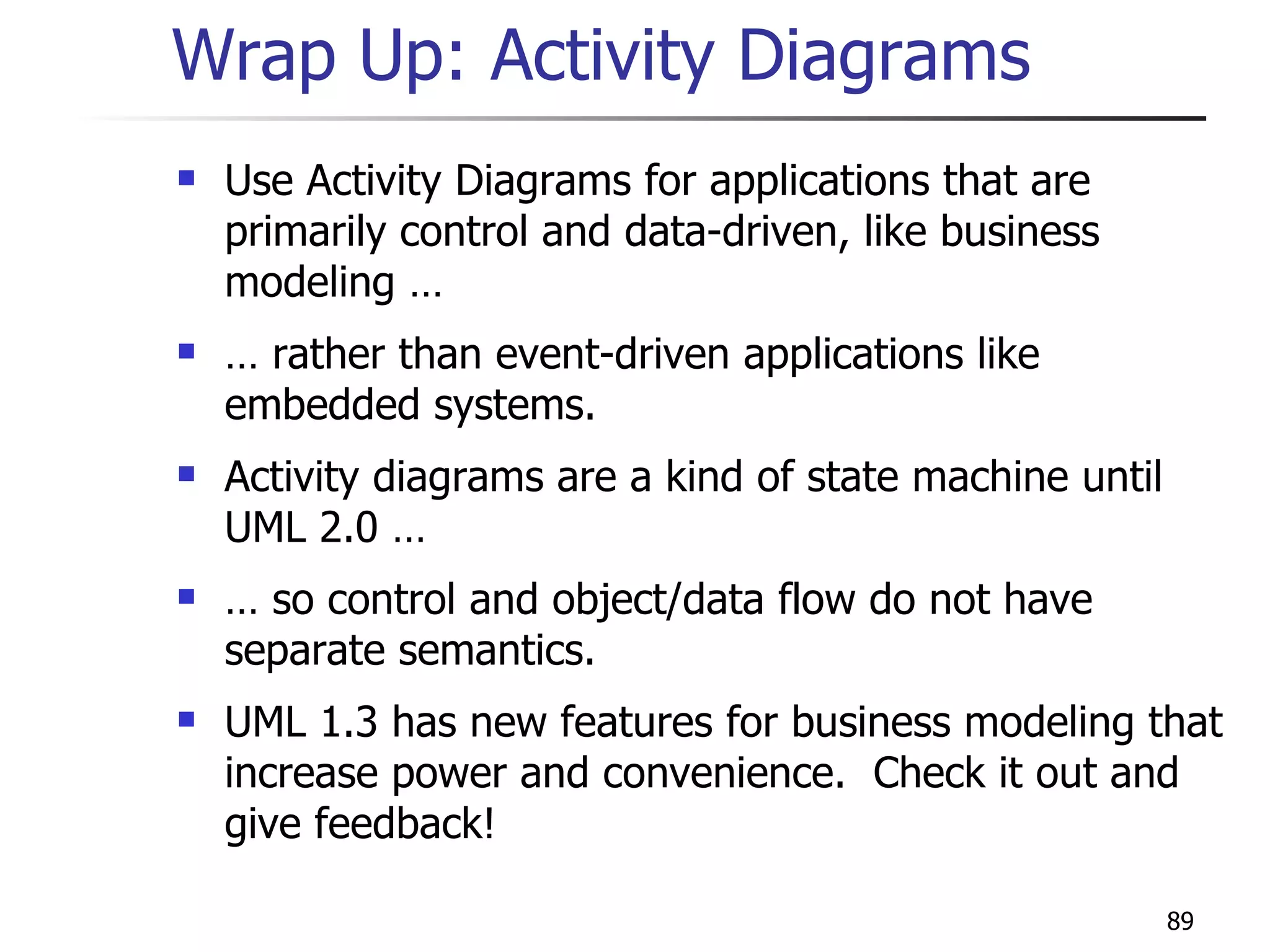
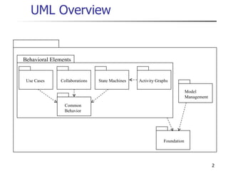
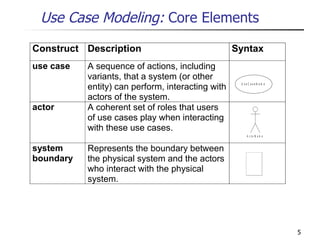
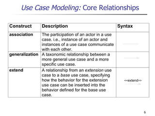
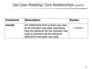
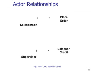
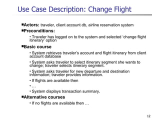
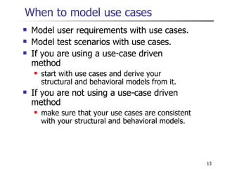
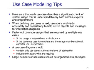
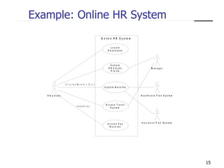
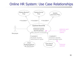
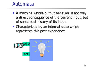
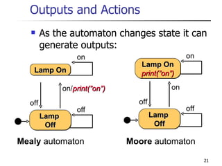
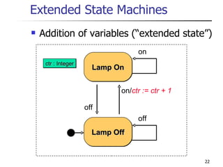
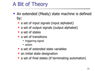
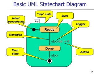
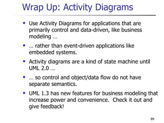
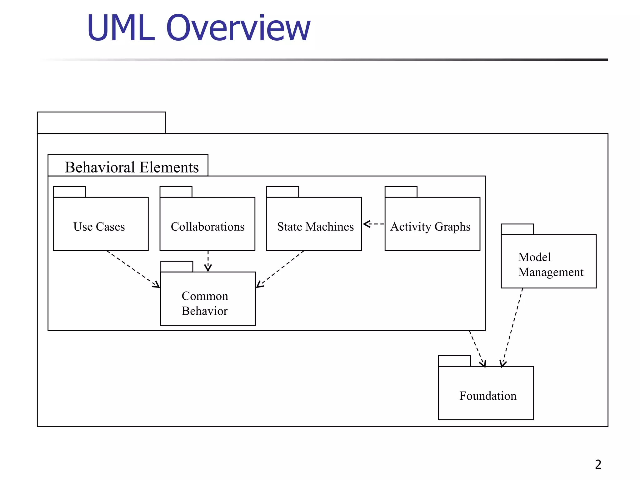
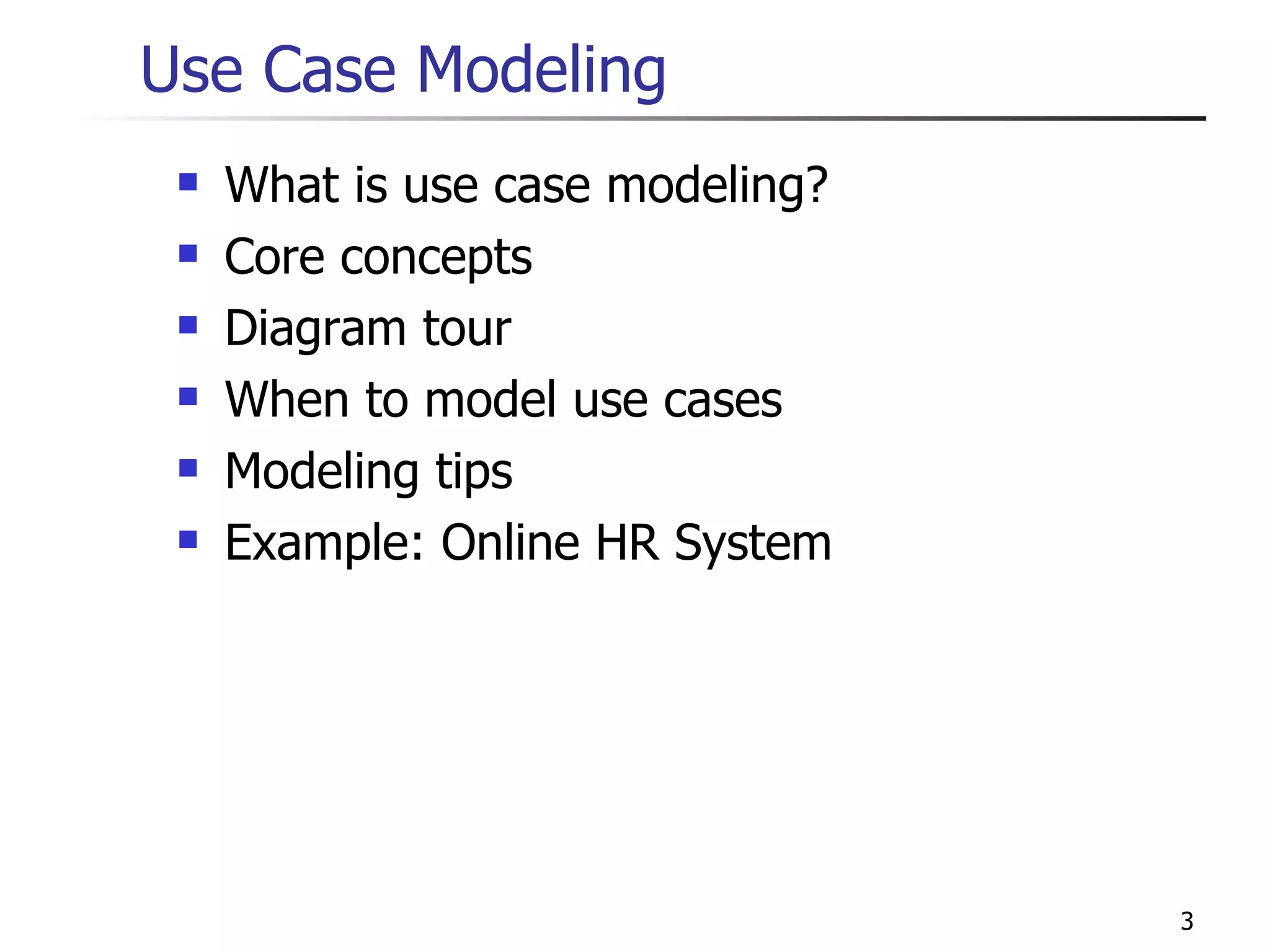
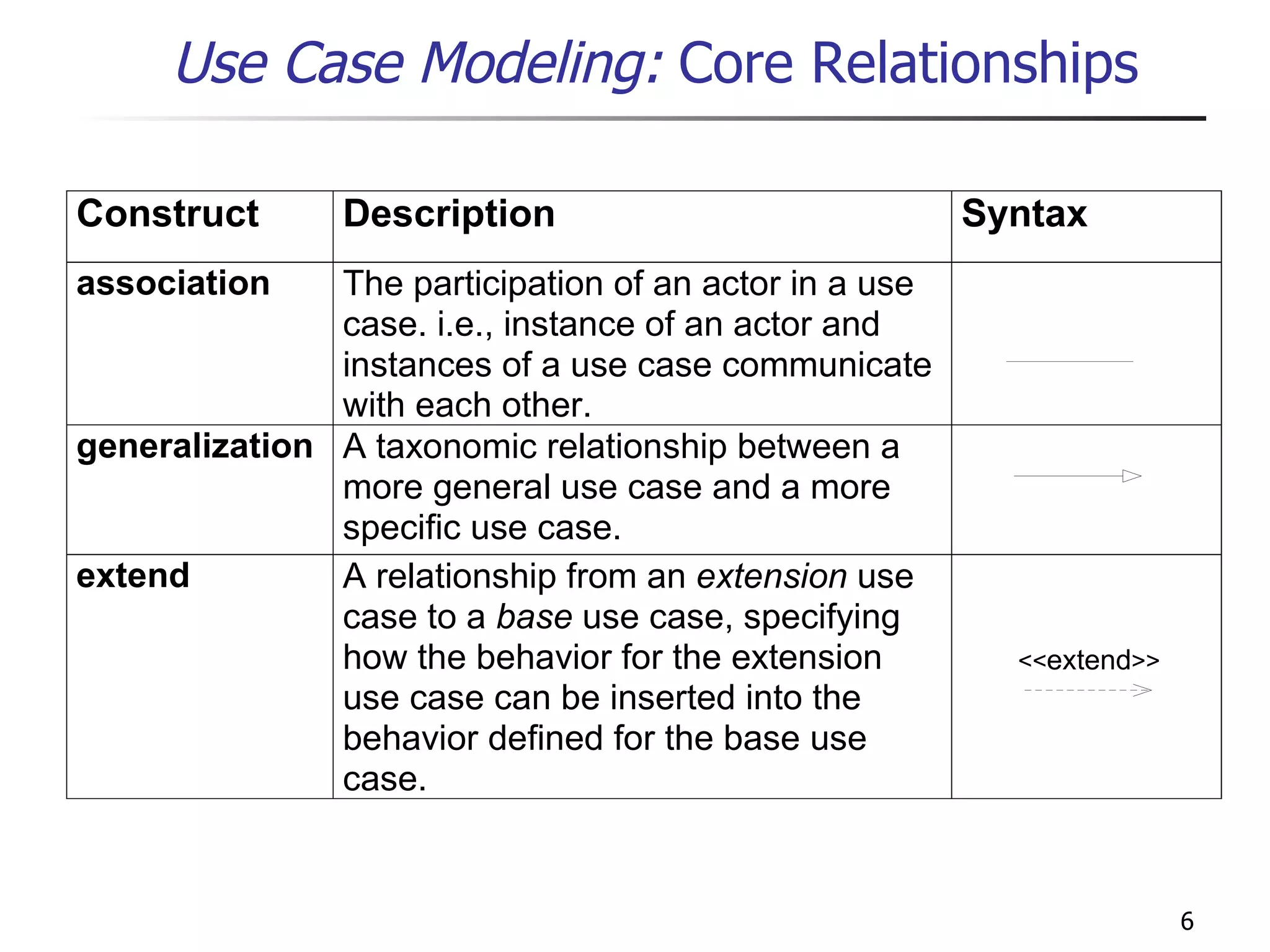
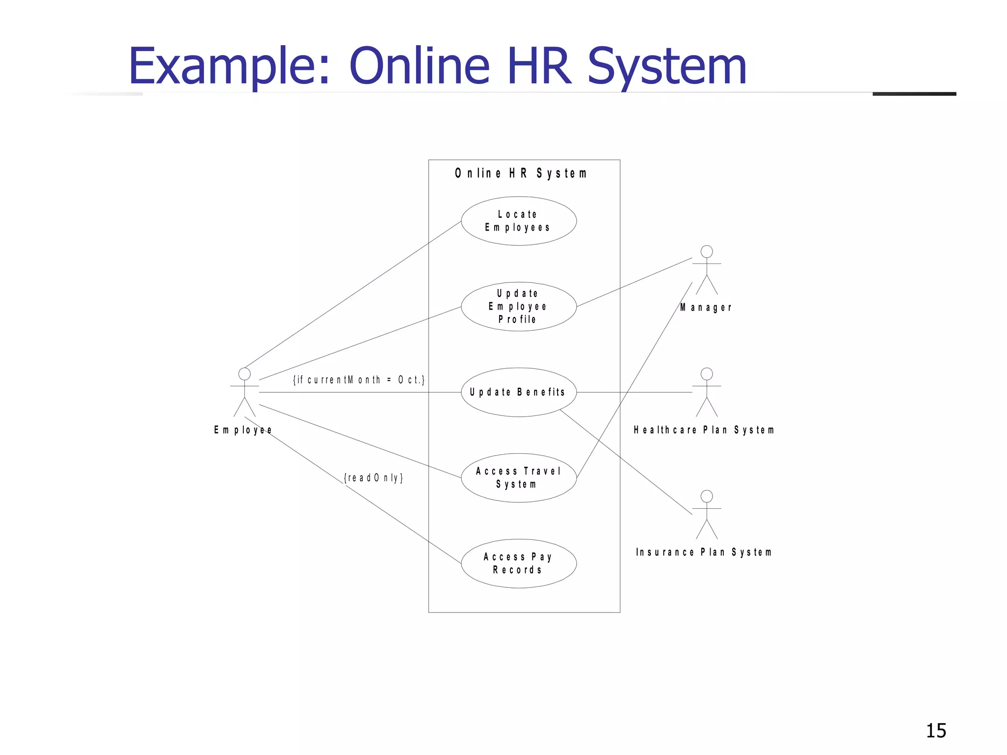
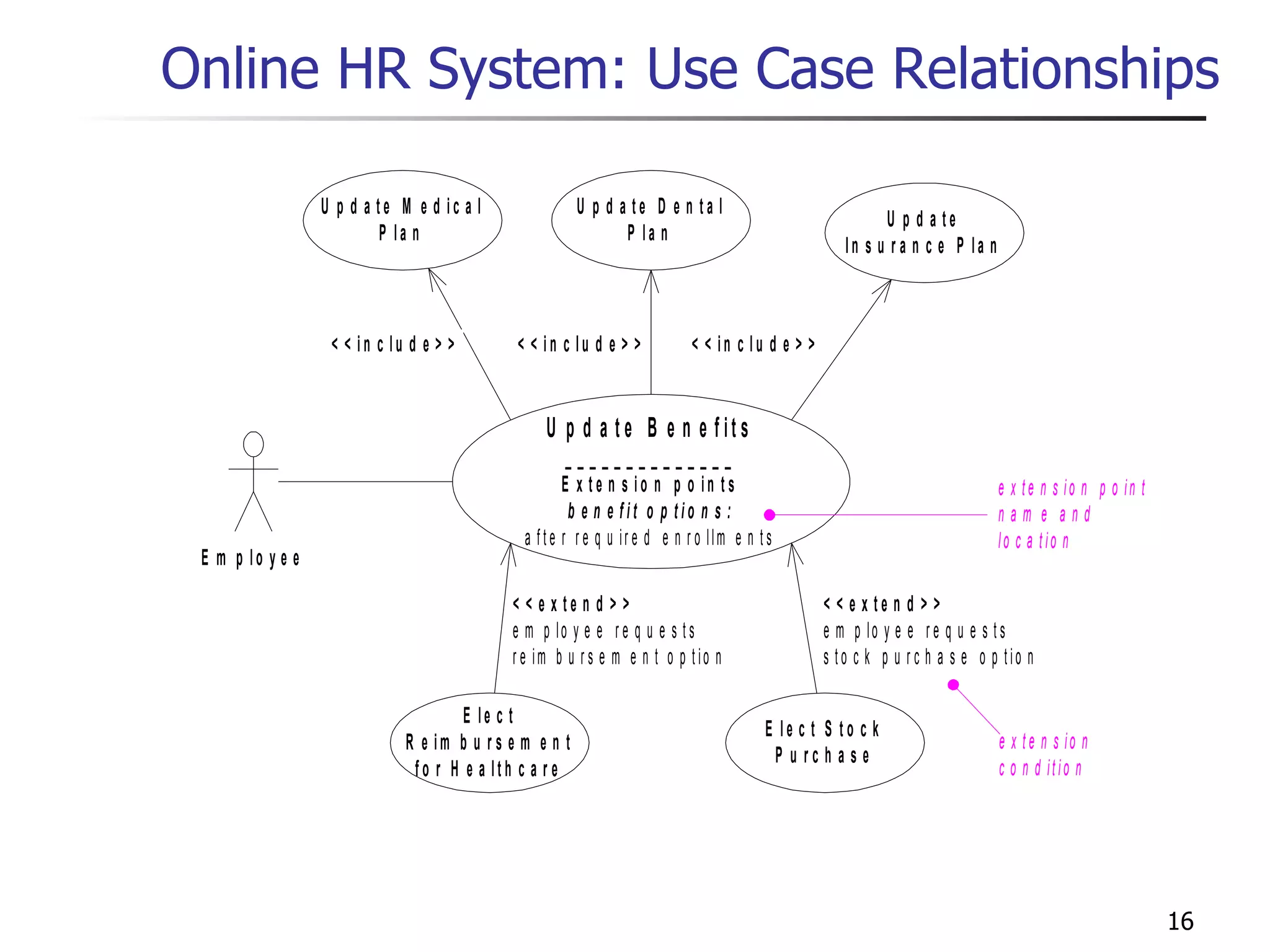
The document provides an overview of use case modeling, state machines, and activity diagrams in UML. It describes core concepts of use case modeling including use cases, actors, and relationships. It also covers when to use use case modeling and provides tips. An example online HR system use case diagram is shown. State machine concepts like states, transitions, entry/exit actions, and hierarchical state machines are explained.


![Guards Conditional execution of transitions guards (Boolean predicates) must be side-effect free Selling Unhappy Happy bid [(value >= 100) & (value < 200)] /sell bid [value >= 200] /sell bid [value < 100] /reject](https://image.slidesharecdn.com/cdocumentsandsettingsstudentdesktopswaroopuml-100630232322-phpapp02/85/C-documents-and-settings-student-desktop-swaroop-uml-41-320.jpg)
![Static Conditional Branching Merely a graphical shortcut for convenient rendering of decision trees [(value >= 100) & (value < 200)] /sell [value >= 200] /sell [value < 100] /reject Selling Unhappy Happy bid](https://image.slidesharecdn.com/cdocumentsandsettingsstudentdesktopswaroopuml-100630232322-phpapp02/85/C-documents-and-settings-student-desktop-swaroop-uml-42-320.jpg)
![Dynamic Conditional Branching Choice pseudostate: guards are evaluated at the instant when the decision point is reached bid / gain := calculatePotentialGain(value) [(gain >= 100) & (gain < 200)] /sell [gain >= 200] /sell [gain < 100] /reject Dynamic choicepoint Selling Unhappy Happy](https://image.slidesharecdn.com/cdocumentsandsettingsstudentdesktopswaroopuml-100630232322-phpapp02/85/C-documents-and-settings-student-desktop-swaroop-uml-43-320.jpg)


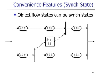
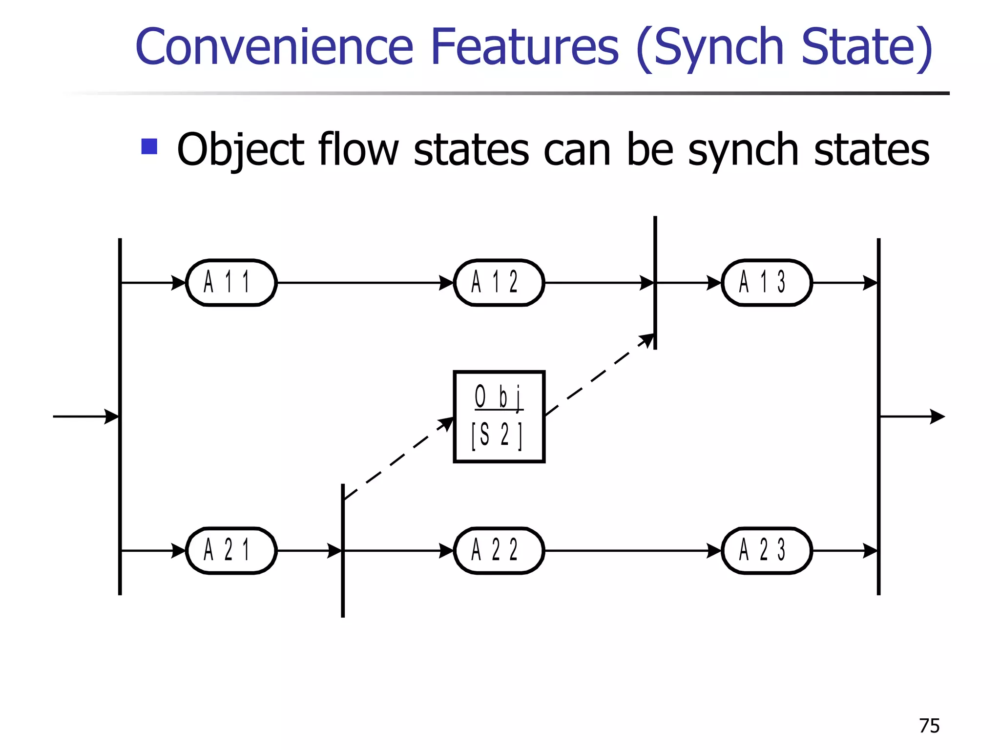
![Object Flow (State) A special sort of step (state) that represents the availability of a particular kind of object, perhaps in a particular state. No action or subactivity is invoked and control passes immediately to the next step (state). Places constraints on input and output parameters of steps before and after it. Class [State]](https://image.slidesharecdn.com/cdocumentsandsettingsstudentdesktopswaroopuml-100630232322-phpapp02/85/C-documents-and-settings-student-desktop-swaroop-uml-69-320.jpg)
![Object Flow (State) Take Order must have an output parameter giving an order, or one of its subtypes. Fill Order must have an input parameter taking an order, or one of its supertypes. Dashed lines used with object flow have the same semantics as any other state transition. Order [Taken] Take Order Fill Order](https://image.slidesharecdn.com/cdocumentsandsettingsstudentdesktopswaroopuml-100630232322-phpapp02/85/C-documents-and-settings-student-desktop-swaroop-uml-70-320.jpg)
![Decision point and merge ( ) are inherited from state machines. For modeling conventional flow chart decisions. Coordinating Steps Calculate Cost Charge Account Get Authorization [cost < $50] [cost >= $50]](https://image.slidesharecdn.com/cdocumentsandsettingsstudentdesktopswaroopuml-100630232322-phpapp02/85/C-documents-and-settings-student-desktop-swaroop-uml-72-320.jpg)

![Convenience Features Fork transitions can have guards. Instead of doing this: Register Bug Evaluate Impact Fix Bug Revise Plan Release Fix Test Fix [ priority = 1] Register Bug Evaluate Impact Fix Bug Revise Plan Release Fix Test Fix [ priority = 1] [else]](https://image.slidesharecdn.com/cdocumentsandsettingsstudentdesktopswaroopuml-100630232322-phpapp02/85/C-documents-and-settings-student-desktop-swaroop-uml-76-320.jpg)
![Convenience Features Partitions are a grouping mechanism. Swimlanes are the notation for partitions. They do not provide domain-specific semantics. Tools can generate swimlane presentation from domain-specific information without partitions. Register Bug Evaluate Impact Fix Bug Revise Plan Release Fix Test Fix [ priority = 1] Management Support Engineering](https://image.slidesharecdn.com/cdocumentsandsettingsstudentdesktopswaroopuml-100630232322-phpapp02/85/C-documents-and-settings-student-desktop-swaroop-uml-77-320.jpg)
![Case Study Adapted from Kobryn, “UML 2001” Communications of the ACM October 1999 partition Submission Team Task Force Revision Task Force Issue RFP Evaluate initial submissions Submit specification draft Collaborate with competitive submitters Develop technology specification action state RFP [issued] [optional] control flow Finalize specification Specification [initial proposal] input value Begin object flow initial state join of control conditional fork fork of control Specification [final proposal]](https://image.slidesharecdn.com/cdocumentsandsettingsstudentdesktopswaroopuml-100630232322-phpapp02/85/C-documents-and-settings-student-desktop-swaroop-uml-79-320.jpg)
![Case Study Adapted from Kobryn, “UML 2001” Communications of the ACM October 1999 Evaluate initial submissions Evaluate final submissions Vote to recommend Enhance specification Implement specification Revise specification Finalize specification Specification [final proposal] Specification [adopted] Recommend revision Specification [revised] [NO] [YES] [else] [Enhanced] decision final state guard Collaborate with competitive submitters](https://image.slidesharecdn.com/cdocumentsandsettingsstudentdesktopswaroopuml-100630232322-phpapp02/85/C-documents-and-settings-student-desktop-swaroop-uml-80-320.jpg)
![Activity Diagram Modeling Tips From UML User Guide: Request Return Get Return Number Ship Item Item [returned] Receive Item Restock Item Credit Account Item [available] Customer Telesales Warehouse Accounting](https://image.slidesharecdn.com/cdocumentsandsettingsstudentdesktopswaroopuml-100630232322-phpapp02/85/C-documents-and-settings-student-desktop-swaroop-uml-83-320.jpg)
![Activity Modeling Tips Request Return Get Return Number Ship Item Item [returned] Receive Item Restock Item Credit Account Item [available] Customer Telesales Warehouse Accounting](https://image.slidesharecdn.com/cdocumentsandsettingsstudentdesktopswaroopuml-100630232322-phpapp02/85/C-documents-and-settings-student-desktop-swaroop-uml-84-320.jpg)


![Guards Conditional execution of transitions guards (Boolean predicates) must be side-effect free Selling Unhappy Happy bid [(value >= 100) & (value < 200)] /sell bid [value >= 200] /sell bid [value < 100] /reject](https://image.slidesharecdn.com/cdocumentsandsettingsstudentdesktopswaroopuml-100630232322-phpapp02/75/C-documents-and-settings-student-desktop-swaroop-uml-41-2048.jpg)
![Static Conditional Branching Merely a graphical shortcut for convenient rendering of decision trees [(value >= 100) & (value < 200)] /sell [value >= 200] /sell [value < 100] /reject Selling Unhappy Happy bid](https://image.slidesharecdn.com/cdocumentsandsettingsstudentdesktopswaroopuml-100630232322-phpapp02/75/C-documents-and-settings-student-desktop-swaroop-uml-42-2048.jpg)
![Dynamic Conditional Branching Choice pseudostate: guards are evaluated at the instant when the decision point is reached bid / gain := calculatePotentialGain(value) [(gain >= 100) & (gain < 200)] /sell [gain >= 200] /sell [gain < 100] /reject Dynamic choicepoint Selling Unhappy Happy](https://image.slidesharecdn.com/cdocumentsandsettingsstudentdesktopswaroopuml-100630232322-phpapp02/75/C-documents-and-settings-student-desktop-swaroop-uml-43-2048.jpg)


![Object Flow (State) A special sort of step (state) that represents the availability of a particular kind of object, perhaps in a particular state. No action or subactivity is invoked and control passes immediately to the next step (state). Places constraints on input and output parameters of steps before and after it. Class [State]](https://image.slidesharecdn.com/cdocumentsandsettingsstudentdesktopswaroopuml-100630232322-phpapp02/75/C-documents-and-settings-student-desktop-swaroop-uml-69-2048.jpg)
![Object Flow (State) Take Order must have an output parameter giving an order, or one of its subtypes. Fill Order must have an input parameter taking an order, or one of its supertypes. Dashed lines used with object flow have the same semantics as any other state transition. Order [Taken] Take Order Fill Order](https://image.slidesharecdn.com/cdocumentsandsettingsstudentdesktopswaroopuml-100630232322-phpapp02/75/C-documents-and-settings-student-desktop-swaroop-uml-70-2048.jpg)

![Decision point and merge ( ) are inherited from state machines. For modeling conventional flow chart decisions. Coordinating Steps Calculate Cost Charge Account Get Authorization [cost < $50] [cost >= $50]](https://image.slidesharecdn.com/cdocumentsandsettingsstudentdesktopswaroopuml-100630232322-phpapp02/75/C-documents-and-settings-student-desktop-swaroop-uml-72-2048.jpg)
![Convenience Features Fork transitions can have guards. Instead of doing this: Register Bug Evaluate Impact Fix Bug Revise Plan Release Fix Test Fix [ priority = 1] Register Bug Evaluate Impact Fix Bug Revise Plan Release Fix Test Fix [ priority = 1] [else]](https://image.slidesharecdn.com/cdocumentsandsettingsstudentdesktopswaroopuml-100630232322-phpapp02/75/C-documents-and-settings-student-desktop-swaroop-uml-76-2048.jpg)
![Convenience Features Partitions are a grouping mechanism. Swimlanes are the notation for partitions. They do not provide domain-specific semantics. Tools can generate swimlane presentation from domain-specific information without partitions. Register Bug Evaluate Impact Fix Bug Revise Plan Release Fix Test Fix [ priority = 1] Management Support Engineering](https://image.slidesharecdn.com/cdocumentsandsettingsstudentdesktopswaroopuml-100630232322-phpapp02/75/C-documents-and-settings-student-desktop-swaroop-uml-77-2048.jpg)

![Case Study Adapted from Kobryn, “UML 2001” Communications of the ACM October 1999 partition Submission Team Task Force Revision Task Force Issue RFP Evaluate initial submissions Submit specification draft Collaborate with competitive submitters Develop technology specification action state RFP [issued] [optional] control flow Finalize specification Specification [initial proposal] input value Begin object flow initial state join of control conditional fork fork of control Specification [final proposal]](https://image.slidesharecdn.com/cdocumentsandsettingsstudentdesktopswaroopuml-100630232322-phpapp02/75/C-documents-and-settings-student-desktop-swaroop-uml-79-2048.jpg)
![Case Study Adapted from Kobryn, “UML 2001” Communications of the ACM October 1999 Evaluate initial submissions Evaluate final submissions Vote to recommend Enhance specification Implement specification Revise specification Finalize specification Specification [final proposal] Specification [adopted] Recommend revision Specification [revised] [NO] [YES] [else] [Enhanced] decision final state guard Collaborate with competitive submitters](https://image.slidesharecdn.com/cdocumentsandsettingsstudentdesktopswaroopuml-100630232322-phpapp02/75/C-documents-and-settings-student-desktop-swaroop-uml-80-2048.jpg)
![Activity Diagram Modeling Tips From UML User Guide: Request Return Get Return Number Ship Item Item [returned] Receive Item Restock Item Credit Account Item [available] Customer Telesales Warehouse Accounting](https://image.slidesharecdn.com/cdocumentsandsettingsstudentdesktopswaroopuml-100630232322-phpapp02/75/C-documents-and-settings-student-desktop-swaroop-uml-83-2048.jpg)
![Activity Modeling Tips Request Return Get Return Number Ship Item Item [returned] Receive Item Restock Item Credit Account Item [available] Customer Telesales Warehouse Accounting](https://image.slidesharecdn.com/cdocumentsandsettingsstudentdesktopswaroopuml-100630232322-phpapp02/75/C-documents-and-settings-student-desktop-swaroop-uml-84-2048.jpg)