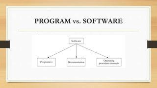
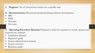
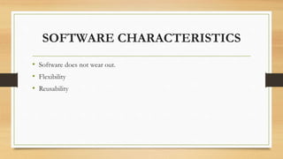
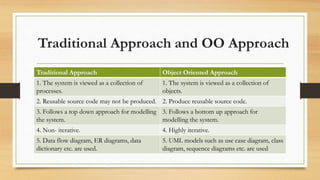
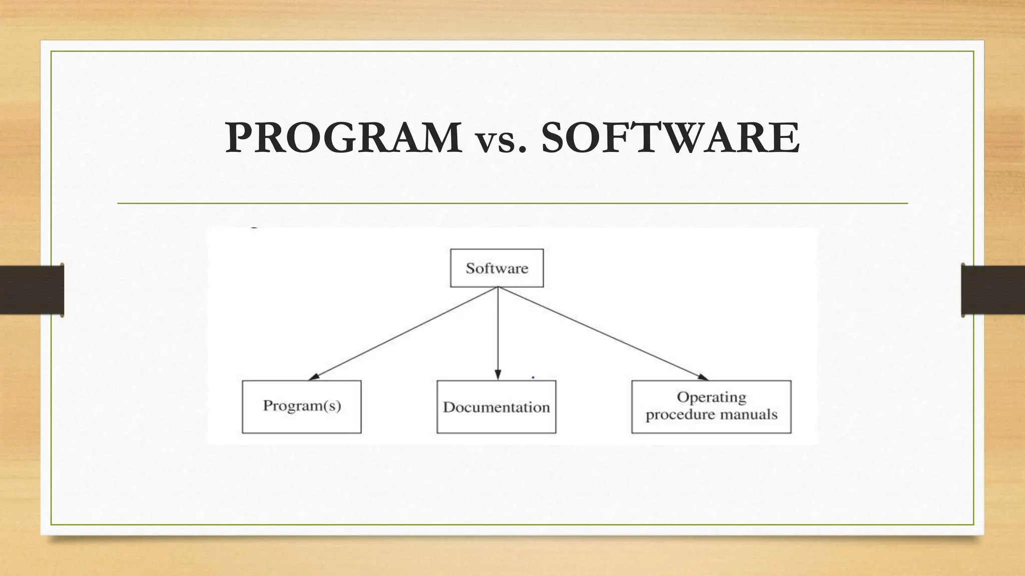
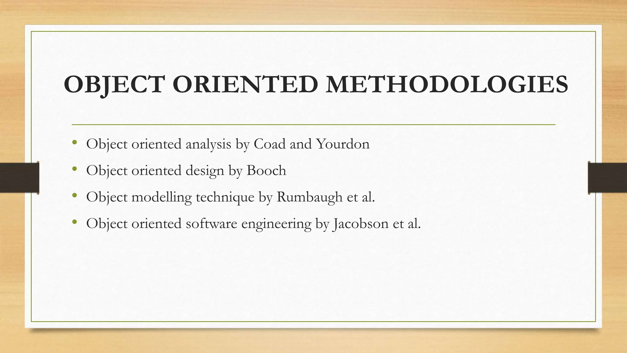
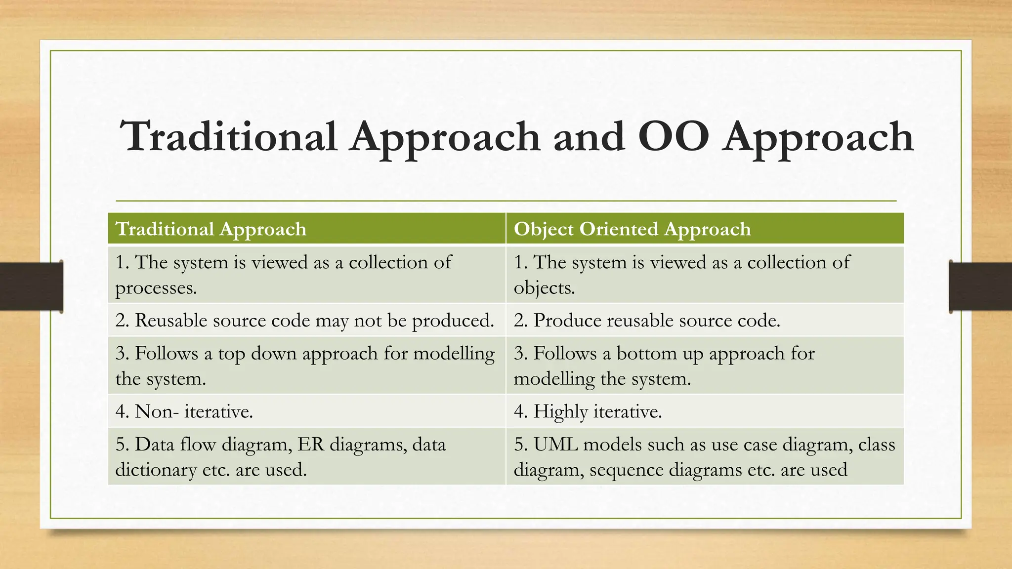
KEMBAR78
Chapter 1-Object Oriented Software Engineering.pptx
CHAPTER 1
INTRODUCTION
PROGRAM vs. SOFTWARE
1. Program: Set of instructions written for a specific task.
2. Documentation: Documents produced during software development.
• SRS
• SDD
• Test plan
• Test suite
3. Operating Procedure Manuals: Prepared to help the customer to install, operate and
maintain the software
• Installation Manual
• Beginner’s guide
• System administration manual
• System overview
• Reference guide
SOFTWARE CHARACTERISTICS
• Software does not wear out.
• Flexibility
• Reusability
Hardware curve Software curve
WHAT IS SOFTWARE ENGINEERING??
• The term ‘software engineering’ was coined at the first conference on software
engineering held in 1968 in which Fritz et al. (1968) defined software engineering as:
The establishment and use of sound engineering principles in order to obtain
economically developed software that is reliable and works efficiently on real
machines.
• IEEE Computer Society’s software engineering body of knowledge defines software
engineering as (Abren et al., 2004):
The application of a systematic, disciplined, quantifiable approach to the
development, operation and maintenance of software, and the study of these
approaches, that is, the application of engineering to software.
OBJECT ORIENTED CONCEPTS
• Classes and Objects
• Messages, Attributes and Methods
• Encapsulation
• Inheritance
• Polymorphism
• Abstraction
OBJECT ORIENTED METHODOLOGIES
• Object oriented analysis by Coad and Yourdon
• Object oriented design by Booch
• Object modelling technique by Rumbaugh et al.
• Object oriented software engineering by Jacobson et al.
COAD AND YOURDON METHODOLOGY
• In OOA, an analysis model is developed and it consists of five steps:
1. Identification of classes and objects
2. Identification of structures
3. Definition of subjects
4. Definition of attributes
5. Definition of services (methods)
BOOCH METHODOLOGY
• The main concern of the Booch methodology is the iterative process and
creativity of designer in order to develop OOD.
• The Booch methodology follows incremental and iterative life cycle.
• It combines analysis, design an implementation and provides a sound object-
oriented software engineering process for analysts, designers and developers.
• The Booch methodology can be broadly divided into two processes: macro
process and micro process
MACRO PROCESS
MICRO PROCESS
• The following recursive steps are followed in OOD micro process:
1. Identification of classes and objects
2. Identification of semantics of classes and objects
3. Identification of relationship amongst classes and objects
4. Specification of interfaces and implementation of classes and objects
RUMBAUGH METHODOLOGY
• Focuses on analysis, design and implementation of the system.
• Popularly known as Object Modelling Technique (OMT) (Rumbaugh et al.,
1990).
• The OMT consists of four phases: analysis, dynamic design, object design
and implementation.
• Analysis phase is composed of 3 models: object model, dynamic model and
functional model.
JACOBSON METHODOLOGY
• The Jacobson’s methodology known as Object-Oriented Software Engineering (OOSE)
consists of five models (Jacobson et al., 1999):
1. The requirement model: The aim of this model is to gather software requirements.
2. The analysis model: The goal of this model is to produce ideal, robust and modifiable
structure of an object.
3. The design model: It refines the objects keeping the implementation environment in mind.
4. The implementation model: It implements the objects.
5. The test model: The goal of the test model is to validate and verify the functionality of the
system
OBJECT ORIENTED MODELING
• Object-oriented modelling is a way of constructing visual models based on
real-world objects. Modelling helps in understanding the problems,
developing proper documents and producing well-designed programs.
• The models must depict the various views of the system and these models
must be verified to check whether they capture the customer’s requirements
• OOD, OMT and OOSE are combined into UML(Unified Modeling
Language).
UML
• The UML was adopted by Object Management Group (OMG) in November 1997.
• The UML is defined as a language for visual modelling that allows to specify,
visualize, construct, understand and document the various artifacts of the system
(Rumbaugh et al. 2004).
• UML models the static and dynamic aspects of the system. The static aspect of the
system models the objects and relationship amongst these objects. The dynamic
aspect of the system models the events and states used for interaction amongst
objects over time.
SOME TERMINOLOGIES
• Customer, Developer and Users: Customers are persons who request the
system, approve the system and pay for the system. Developers are the
persons at the supplier side who are responsible for the development of the
system. Users are the persons who actually use the system.
• Product and Process: Product is what is delivered to the customer. It may
include software requirement specification (SRS) document, source code, test
reports, user manuals and system guide. Process is the way in which the
software is produced. A process is like a tunnel through which the project
goes in order to produce a product.
• Actor, Use cases, Use case model and Use case scenario: An actor
represents the role of a user that interacts with the system. A use case describes
who does what with the system, for what goal, without considering the internal
details of the system. A complete set of use cases explains the various ways to use
the system. The use case model depicts actors, use cases and the relationship
between them. A use case scenario is an instance of a use case or a complete path
through the use case. The basic flow is one scenario and every alternative path
gives another scenario.
• Systems and Subsystems: A system is an organized and arranged structure as a
whole that consists of interrelated and well-defined procedures, processes and
methods. The system may consist of several subsystems. Subsystems are a way of
reducing complexity of the system.
• Class, Responsibility and Collaboration: A class is a template that consists of
attributes and operations. Responsibilities are attributes and operations included
in a class. Collaborations are the other classes that a class calls in order to achieve
the functionality.
• Measures, Metrics and Measurement: Pressman (2005) explained this clearly
as: “A measure provides a quantitative indication of the extent, amount,
dimension, capacity or size of some attributes of a product or process.
Measurement is the act of determining a measure. The metric is a quantitative
measure of the degree to which a product or process possesses a given attribute.”
• Software Quality and Reliability: Software reliability is defined as “the
probability of failure free operation for a specified time in a specified
environment” (ANSI, 1991). Software quality determines how good the software
designed is (quality of design), and how good the software conforms to that
design (quality of conformance).
• Quality assurance and Quality control: The purpose of quality assurance (QA)
activity is to enforce standards and techniques to improve the development
process and prevent the previous bugs from ever occurring. Quality control
attempts to build a software and test it thoroughly. If failures are experienced,
remove the causes of failures and ensure the correctness of removal.
• Verification and Validation: As per IEEE (2001) verification is defined as, “It is
the process of evaluating the system or component to determine whether the
products of a given development phase satisfy the conditions imposed at the start
of that phase”. As per IEEE (2001) validation is defined as, “It is the process of
evaluating a system or component during or at the end of development process
to determine whether it satisfies the specified requirements”.
Testing = Verification + Validation
• Fault, Error, Bug and Failure: When we make an error during coding, we call
this ‘bug’. Hence, error/mistake/defect in coding is called a bug. A fault is the
representation of an error. If the fault is in the source code, we call it a bug. A
failure is the result of execution of a fault and is dynamic in nature. When the
expected output does not match with the observed output, we experience a
failure. The program has to execute for a failure to occur. A fault may lead to
many failures. A particular fault may cause different failures, depending on the
inputs to the program.
• States and Events: A state is an abstract situation in the life cycle of an entity
that occurs in response to occurrence of some event. An event is an input (a
message or method call). Due to the occurrence of some event, the system
transits from one state to the other.
Traditional Approach and OO Approach
Traditional Approach Object Oriented Approach
1. The system is viewed as a collection of
processes.
1. The system is viewed as a collection of
objects.
2. Reusable source code may not be produced. 2. Produce reusable source code.
3. Follows a top down approach for modelling
the system.
3. Follows a bottom up approach for
modelling the system.
4. Non- iterative. 4. Highly iterative.
5. Data flow diagram, ER diagrams, data
dictionary etc. are used.
5. UML models such as use case diagram, class
diagram, sequence diagrams etc. are used

Chapter 1-Object Oriented Software Engineering.pptx

  • 1.
  • 2.
  • 3.
    1. Program: Setof instructions written for a specific task. 2. Documentation: Documents produced during software development. • SRS • SDD • Test plan • Test suite 3. Operating Procedure Manuals: Prepared to help the customer to install, operate and maintain the software • Installation Manual • Beginner’s guide • System administration manual • System overview • Reference guide
  • 4.
    SOFTWARE CHARACTERISTICS • Softwaredoes not wear out. • Flexibility • Reusability
  • 5.
  • 6.
    WHAT IS SOFTWAREENGINEERING?? • The term ‘software engineering’ was coined at the first conference on software engineering held in 1968 in which Fritz et al. (1968) defined software engineering as: The establishment and use of sound engineering principles in order to obtain economically developed software that is reliable and works efficiently on real machines. • IEEE Computer Society’s software engineering body of knowledge defines software engineering as (Abren et al., 2004): The application of a systematic, disciplined, quantifiable approach to the development, operation and maintenance of software, and the study of these approaches, that is, the application of engineering to software.
  • 7.
    OBJECT ORIENTED CONCEPTS •Classes and Objects • Messages, Attributes and Methods • Encapsulation • Inheritance • Polymorphism • Abstraction
  • 8.
    OBJECT ORIENTED METHODOLOGIES •Object oriented analysis by Coad and Yourdon • Object oriented design by Booch • Object modelling technique by Rumbaugh et al. • Object oriented software engineering by Jacobson et al.
  • 9.
    COAD AND YOURDONMETHODOLOGY • In OOA, an analysis model is developed and it consists of five steps: 1. Identification of classes and objects 2. Identification of structures 3. Definition of subjects 4. Definition of attributes 5. Definition of services (methods)
  • 11.
    BOOCH METHODOLOGY • Themain concern of the Booch methodology is the iterative process and creativity of designer in order to develop OOD. • The Booch methodology follows incremental and iterative life cycle. • It combines analysis, design an implementation and provides a sound object- oriented software engineering process for analysts, designers and developers. • The Booch methodology can be broadly divided into two processes: macro process and micro process
  • 12.
  • 13.
    MICRO PROCESS • Thefollowing recursive steps are followed in OOD micro process: 1. Identification of classes and objects 2. Identification of semantics of classes and objects 3. Identification of relationship amongst classes and objects 4. Specification of interfaces and implementation of classes and objects
  • 14.
    RUMBAUGH METHODOLOGY • Focuseson analysis, design and implementation of the system. • Popularly known as Object Modelling Technique (OMT) (Rumbaugh et al., 1990). • The OMT consists of four phases: analysis, dynamic design, object design and implementation. • Analysis phase is composed of 3 models: object model, dynamic model and functional model.
  • 15.
    JACOBSON METHODOLOGY • TheJacobson’s methodology known as Object-Oriented Software Engineering (OOSE) consists of five models (Jacobson et al., 1999): 1. The requirement model: The aim of this model is to gather software requirements. 2. The analysis model: The goal of this model is to produce ideal, robust and modifiable structure of an object. 3. The design model: It refines the objects keeping the implementation environment in mind. 4. The implementation model: It implements the objects. 5. The test model: The goal of the test model is to validate and verify the functionality of the system
  • 16.
    OBJECT ORIENTED MODELING •Object-oriented modelling is a way of constructing visual models based on real-world objects. Modelling helps in understanding the problems, developing proper documents and producing well-designed programs. • The models must depict the various views of the system and these models must be verified to check whether they capture the customer’s requirements • OOD, OMT and OOSE are combined into UML(Unified Modeling Language).
  • 17.
    UML • The UMLwas adopted by Object Management Group (OMG) in November 1997. • The UML is defined as a language for visual modelling that allows to specify, visualize, construct, understand and document the various artifacts of the system (Rumbaugh et al. 2004). • UML models the static and dynamic aspects of the system. The static aspect of the system models the objects and relationship amongst these objects. The dynamic aspect of the system models the events and states used for interaction amongst objects over time.
  • 18.
    SOME TERMINOLOGIES • Customer,Developer and Users: Customers are persons who request the system, approve the system and pay for the system. Developers are the persons at the supplier side who are responsible for the development of the system. Users are the persons who actually use the system. • Product and Process: Product is what is delivered to the customer. It may include software requirement specification (SRS) document, source code, test reports, user manuals and system guide. Process is the way in which the software is produced. A process is like a tunnel through which the project goes in order to produce a product.
  • 19.
    • Actor, Usecases, Use case model and Use case scenario: An actor represents the role of a user that interacts with the system. A use case describes who does what with the system, for what goal, without considering the internal details of the system. A complete set of use cases explains the various ways to use the system. The use case model depicts actors, use cases and the relationship between them. A use case scenario is an instance of a use case or a complete path through the use case. The basic flow is one scenario and every alternative path gives another scenario. • Systems and Subsystems: A system is an organized and arranged structure as a whole that consists of interrelated and well-defined procedures, processes and methods. The system may consist of several subsystems. Subsystems are a way of reducing complexity of the system.
  • 20.
    • Class, Responsibilityand Collaboration: A class is a template that consists of attributes and operations. Responsibilities are attributes and operations included in a class. Collaborations are the other classes that a class calls in order to achieve the functionality. • Measures, Metrics and Measurement: Pressman (2005) explained this clearly as: “A measure provides a quantitative indication of the extent, amount, dimension, capacity or size of some attributes of a product or process. Measurement is the act of determining a measure. The metric is a quantitative measure of the degree to which a product or process possesses a given attribute.” • Software Quality and Reliability: Software reliability is defined as “the probability of failure free operation for a specified time in a specified environment” (ANSI, 1991). Software quality determines how good the software designed is (quality of design), and how good the software conforms to that design (quality of conformance).
  • 21.
    • Quality assuranceand Quality control: The purpose of quality assurance (QA) activity is to enforce standards and techniques to improve the development process and prevent the previous bugs from ever occurring. Quality control attempts to build a software and test it thoroughly. If failures are experienced, remove the causes of failures and ensure the correctness of removal. • Verification and Validation: As per IEEE (2001) verification is defined as, “It is the process of evaluating the system or component to determine whether the products of a given development phase satisfy the conditions imposed at the start of that phase”. As per IEEE (2001) validation is defined as, “It is the process of evaluating a system or component during or at the end of development process to determine whether it satisfies the specified requirements”. Testing = Verification + Validation
  • 22.
    • Fault, Error,Bug and Failure: When we make an error during coding, we call this ‘bug’. Hence, error/mistake/defect in coding is called a bug. A fault is the representation of an error. If the fault is in the source code, we call it a bug. A failure is the result of execution of a fault and is dynamic in nature. When the expected output does not match with the observed output, we experience a failure. The program has to execute for a failure to occur. A fault may lead to many failures. A particular fault may cause different failures, depending on the inputs to the program. • States and Events: A state is an abstract situation in the life cycle of an entity that occurs in response to occurrence of some event. An event is an input (a message or method call). Due to the occurrence of some event, the system transits from one state to the other.
  • 23.
    Traditional Approach andOO Approach Traditional Approach Object Oriented Approach 1. The system is viewed as a collection of processes. 1. The system is viewed as a collection of objects. 2. Reusable source code may not be produced. 2. Produce reusable source code. 3. Follows a top down approach for modelling the system. 3. Follows a bottom up approach for modelling the system. 4. Non- iterative. 4. Highly iterative. 5. Data flow diagram, ER diagrams, data dictionary etc. are used. 5. UML models such as use case diagram, class diagram, sequence diagrams etc. are used

Editor's Notes

  • #9 Methodology is a set of methods and principles that signify a systematic way of developing a system using tools, techniques, processes and procedures
  • #10 Coad and Yourdon’s methodology is popularly known as Object-Oriented Analysis (OOA) (Coad and Yourdon, 1990). It was developed in the late 1980s. Identification of classes and objects involves investigating the application domain and the system’s environment. The behaviour of each object is found and this information is documented. Identification of structures involves identification of is-a and whole-part relationships. The is-a relationship captures class inheritance (known as Gen-Spec structure) and the the whole-part relationship captures the information about how an object is a part of another object. Each structure is classified into a subject. Attributes are the data members of the class. The attributes for each object are defined and kept at the appropriate level in the inheritance hierarchy. Defining services involves identification of operations in a class. This also involves identification of interfaces amongst the objects through messages. Each message may contain parameters for communication. In the OOA methodology, there is no systematic way to identify classes and objects. The interfaces are also not determined in this methodology.
  • #12 The primary aim of OOD was to establish a base for the implementation of object-oriented systems. The Booch methodology considered identification of interfaces at various levels.
  • #13 It is a high-level process that describes the activities to be followed by the development team throughout the life cycle. In the first phase, the requirements are established using context diagrams and prototypes. The outcomes of this phase are core requirements of the system. The analysis process involves requirement capturing and understanding. It involves “what of the system”. This phase consists of construction of use cases, identification and prioritization of risks. The design phase focuses on the construction of architecture of the system and involves: Identifying horizontal layers Mapping classes to subsystems Release planning Attaching risks identified in the analysis phase to releases The evolutionary phase involves implementation of the system and each release adds to the functionality of the system. The maintenance phase consists of post-deployment activities.
  • #14 It is a lower level process. Identification of classes and objects involves finding of classes and objects at specific level of abstraction. The second step identifies the semantics of the classes and objects by finding the meaning of the classes and objects in terms of attributes and operations. It also involves determining the use of an object by another object. Identification of relationship involves the process of determining the interaction amongst the classes and objects. The relationships identified include inheritance, uses and instance of. The last step involves specification of interface amongst classes and objects and their implementation. It identifies data type of attributes and signature of operations.
  • #15 Analysis phase: Analysis phase is composed of three submodels given below: Object model: It captures the static aspect of the system. Dynamic model: It captures the behavioural aspects of the object models and describes state of the objects. Functional model: It represents the functional aspects of the system in terms of operations defined in the classes. In the object model, the requirements are stated in the problem statement. The relevant classes along with inheritance relationships are extracted from this problem statement. The dynamic model identifies states and events in the classes identified in object models. The functional model depicts the functionality of the system by creating data flow diagrams of the system in order to understand the processes (in the form of input and output information). System design phase: In this phase, a high-level design is developed taking the implementation environment including DBMS and communication protocols into account. Object design phase: The goal of this phase is to define the objects in detail. The algorithms and operations of the objects are defined in this phase. New objects may be identified to represent the intermediate functionality. Implementation phase: Finally, the objects are implemented following coding standards and guidelines
  • #16 The requirement model focuses on capturing functionality of the system through use cases and actors and determining the interfaces amongst the use cases. In the analysis model, an ideal model is developed while not considering the implementation environment. It involves the identification of interface objects, database-related objects (entity objects) and objects representing control between interface and database-related objects (control objects). The objects are grouped into subsystems. In the design model the objects identified in the analysis model, are refined to the actual implementation environment. These objects are called blocks. These blocks are converted into modules in the implementation model and finally the modules are integrated and tested in the test model. All the methods discussed above have their own advantages and disadvantages. The OOA method lacks the design of interfaces and notations. The OOD method is stronger in design but weaker in analysis of the system. The OMT method is stronger in analysis part but weaker in design part. The Jacobson’s methodology is stronger in behavioural areas as compared to the other areas