Downloaded 608 times


This document discusses various mechanical testing and non-destructive testing methods. Mechanical tests determine properties like strength, hardness, elasticity and ductility by applying loads or forces that often damage specimens. Hardness tests include Brinell, Vickers and Rockwell methods. Impact tests include Izod and Charpy tests. Non-destructive tests like magnetic particle, ultrasonic and X-ray methods detect subsurface flaws without harming samples.
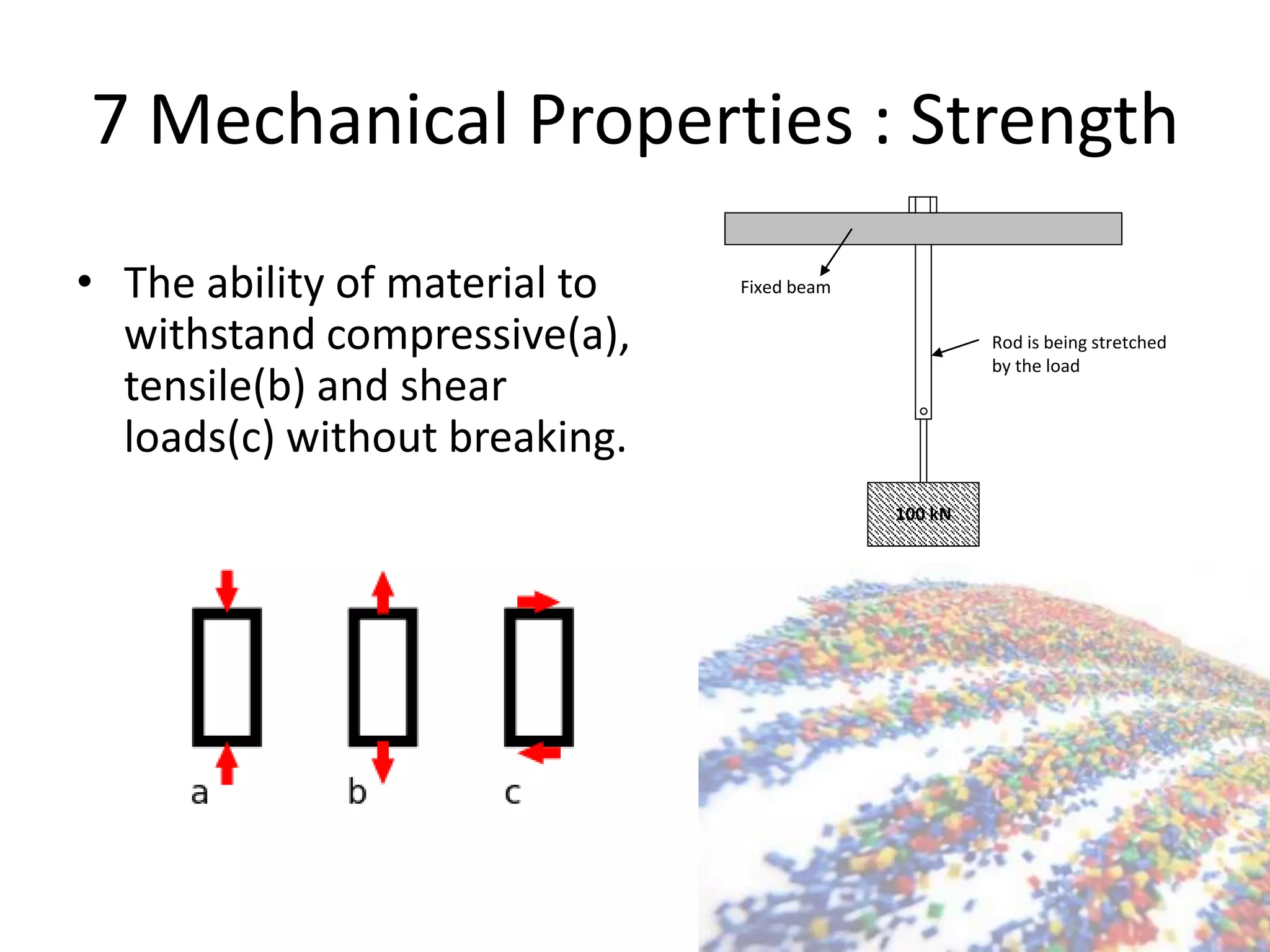
Introduction to mechanical testing, evaluating materials' ability to resist forces like tension and compression.
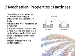
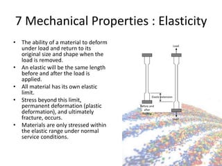
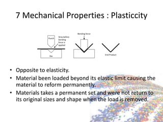
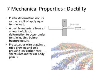
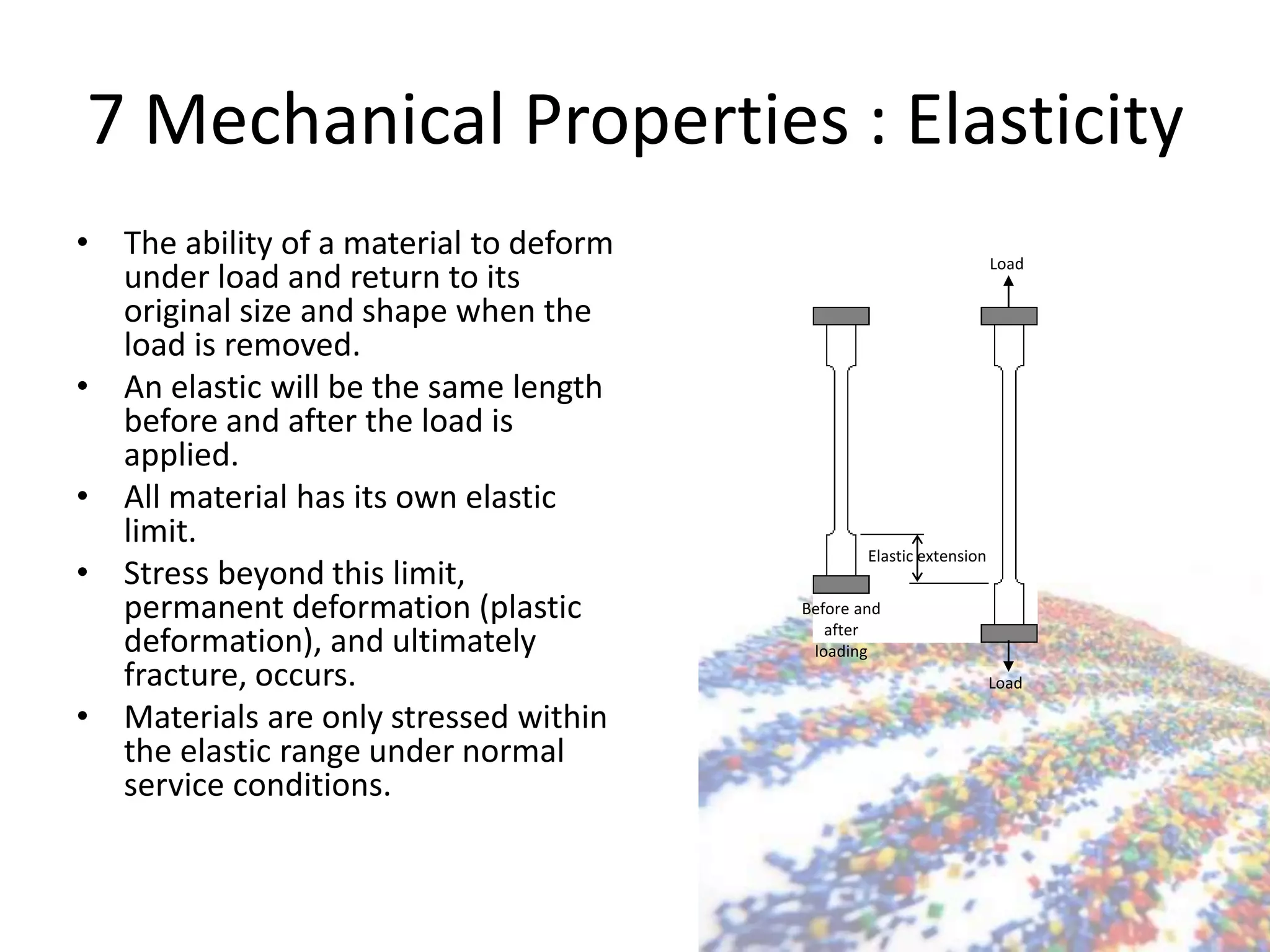
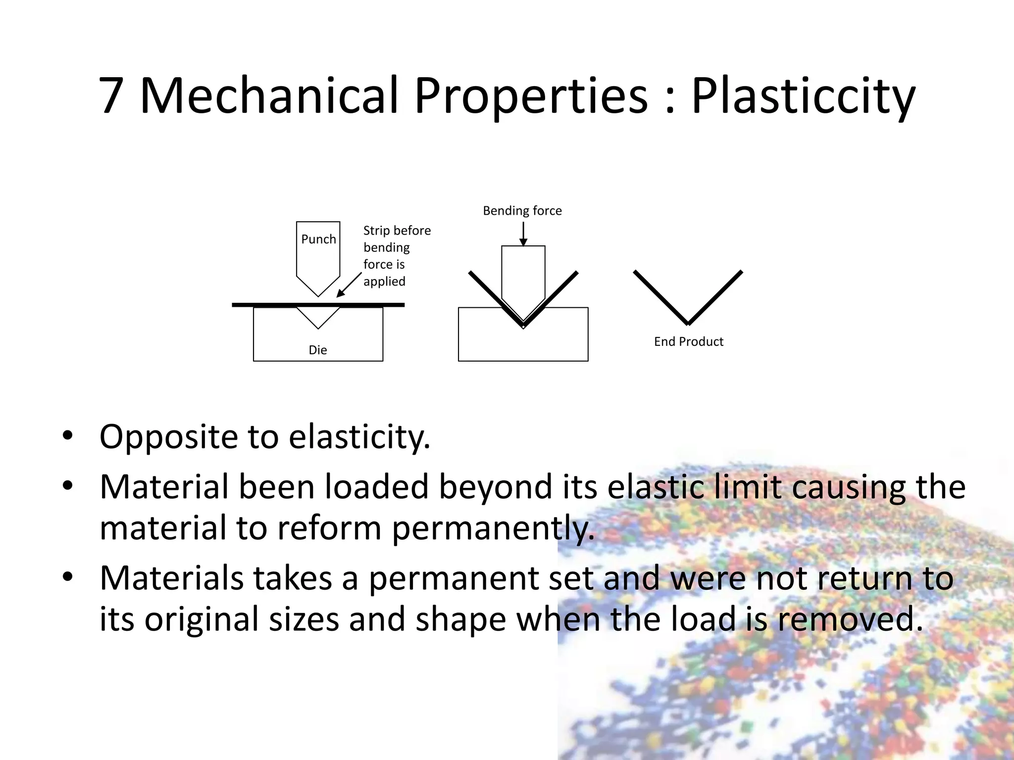
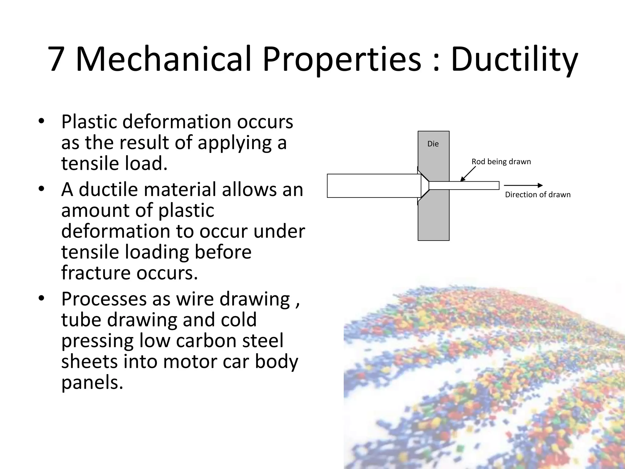
Exploring 7 mechanical properties: strength, hardness, elasticity, plasticity, ductility, toughness, brittleness.
Destructive testing impacts material shape; includes tests for speed and pressure.
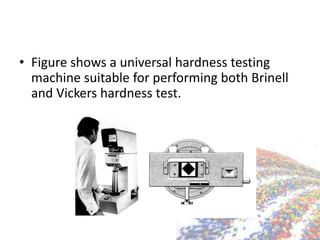
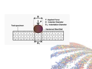
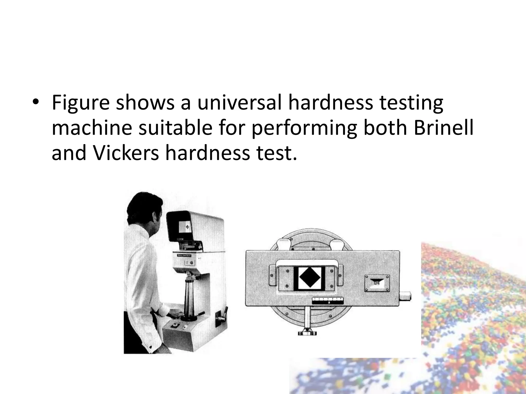
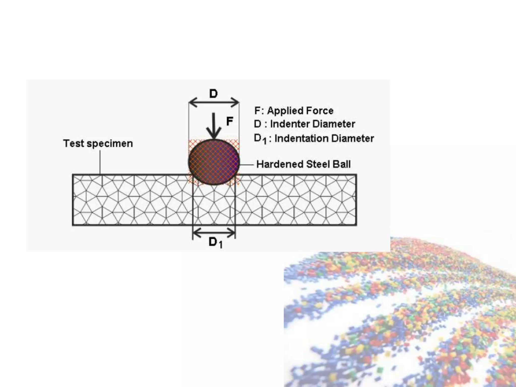
Highlights various hardness tests: Brinell, Vickers, and their procedures to measure material hardness.
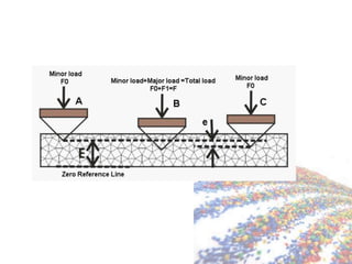
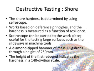
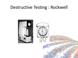
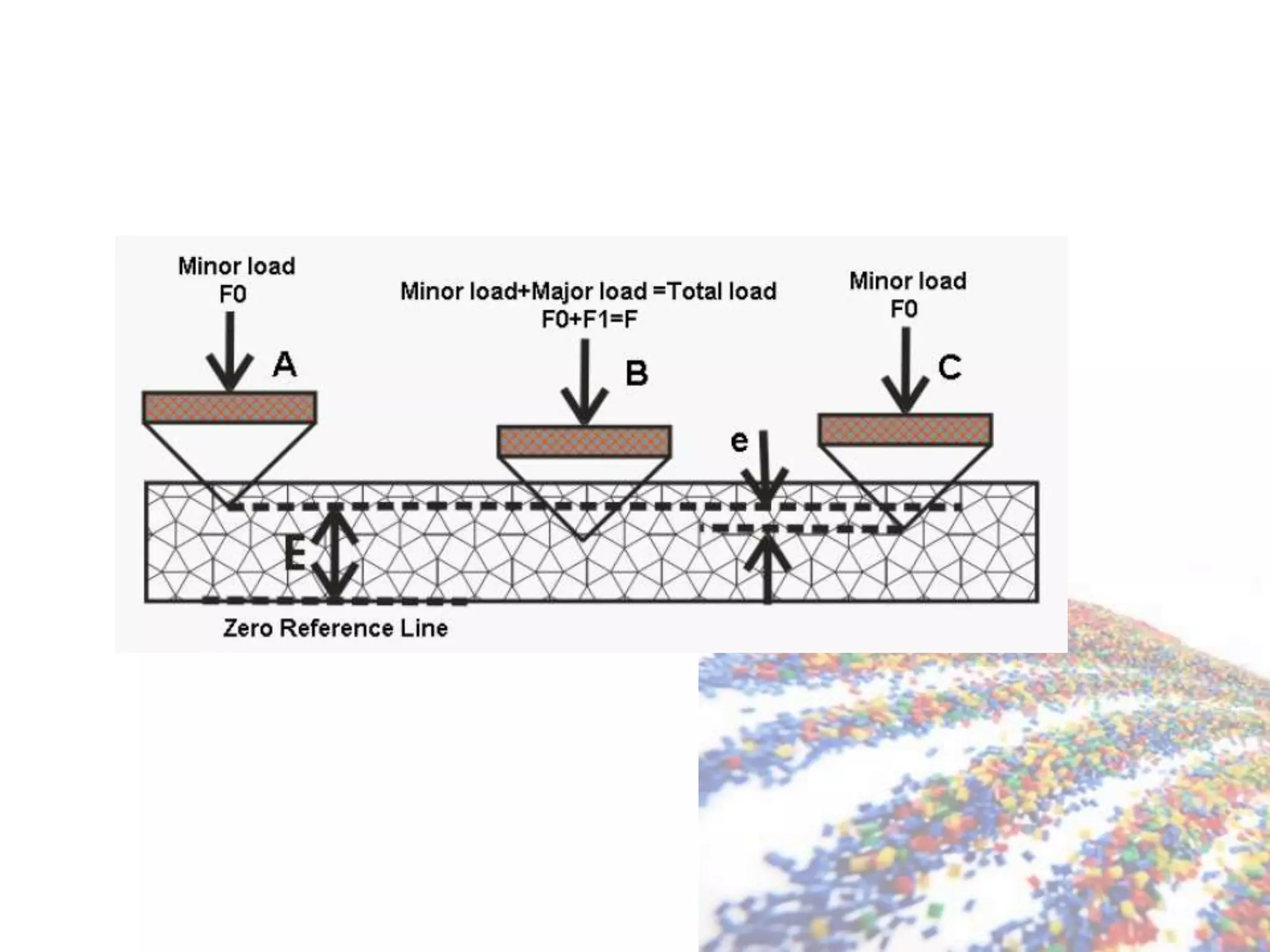
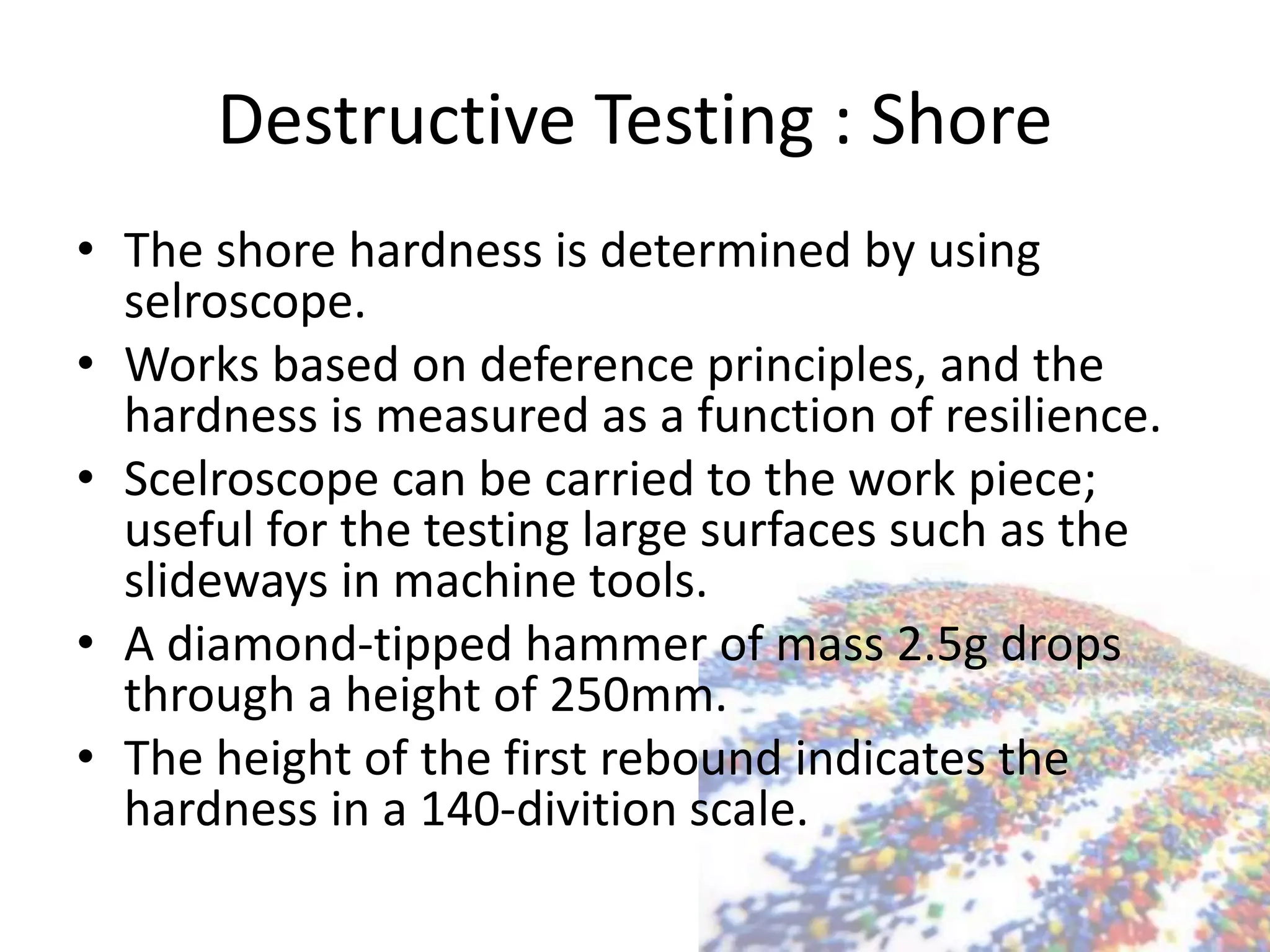
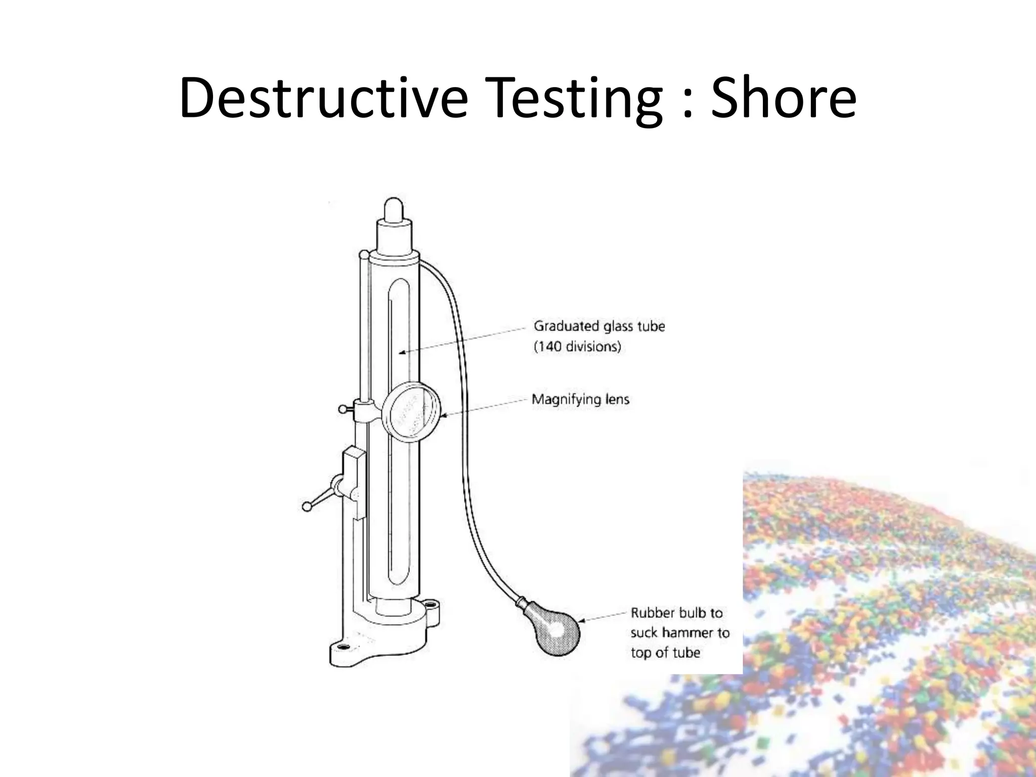
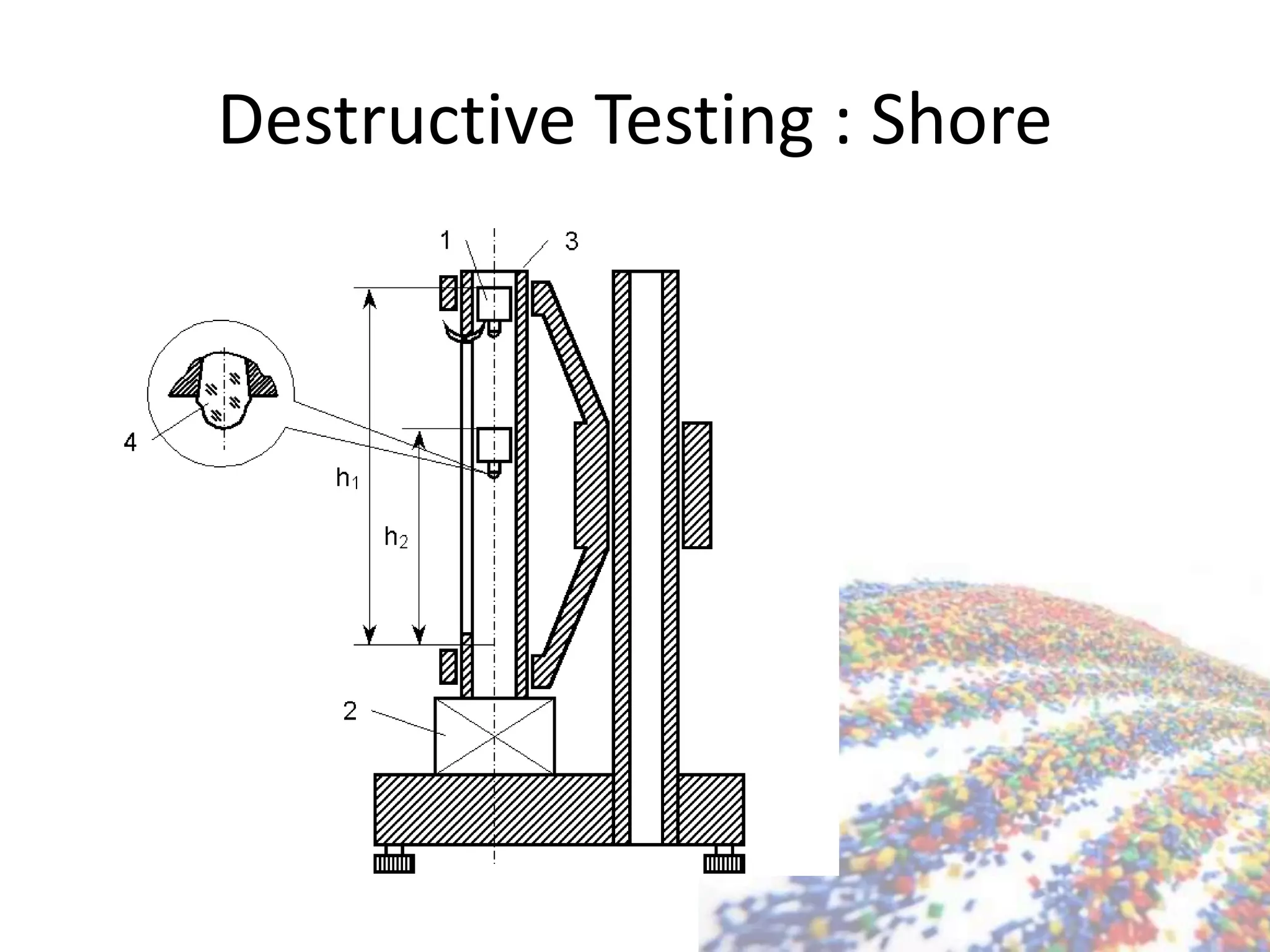
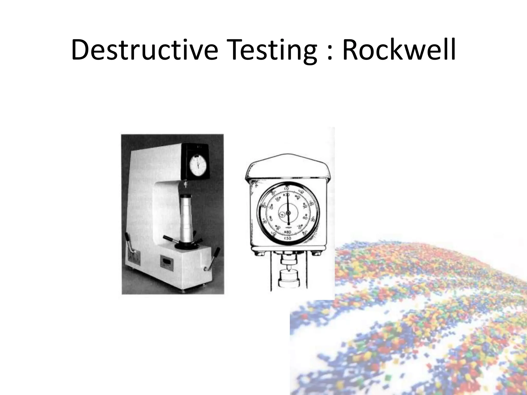
Shore hardness testing and Rockwell method; quick and simple steps to determine hardness.
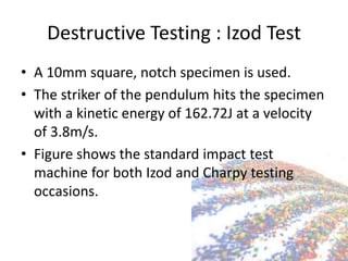
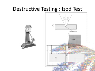
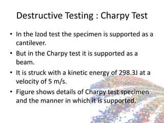
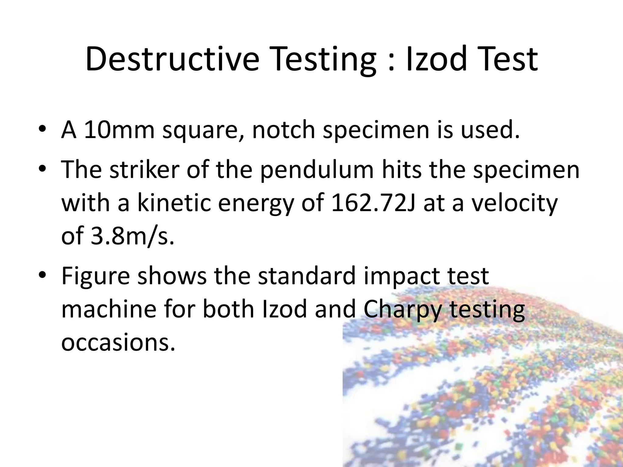
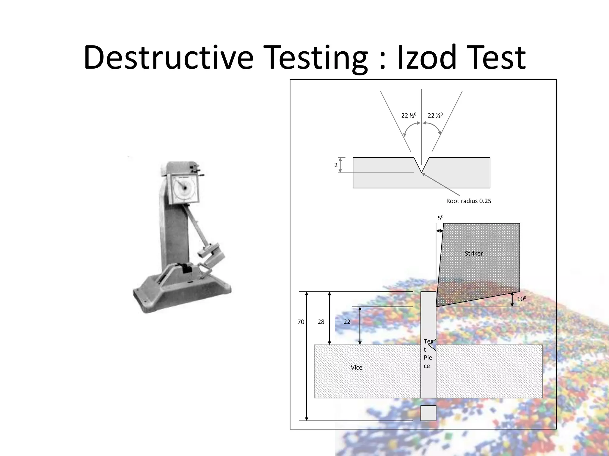
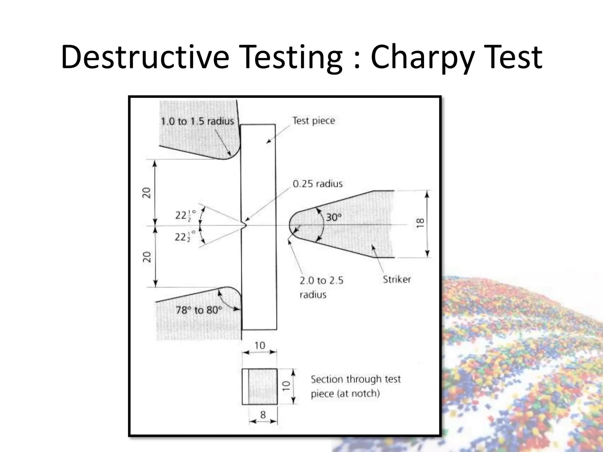
Describes Izod and Charpy tests; measuring impact energy with specific setups.
Defining NDT and its purpose to identify material discontinuities without causing damage.
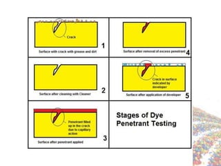
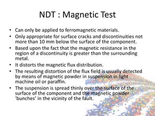
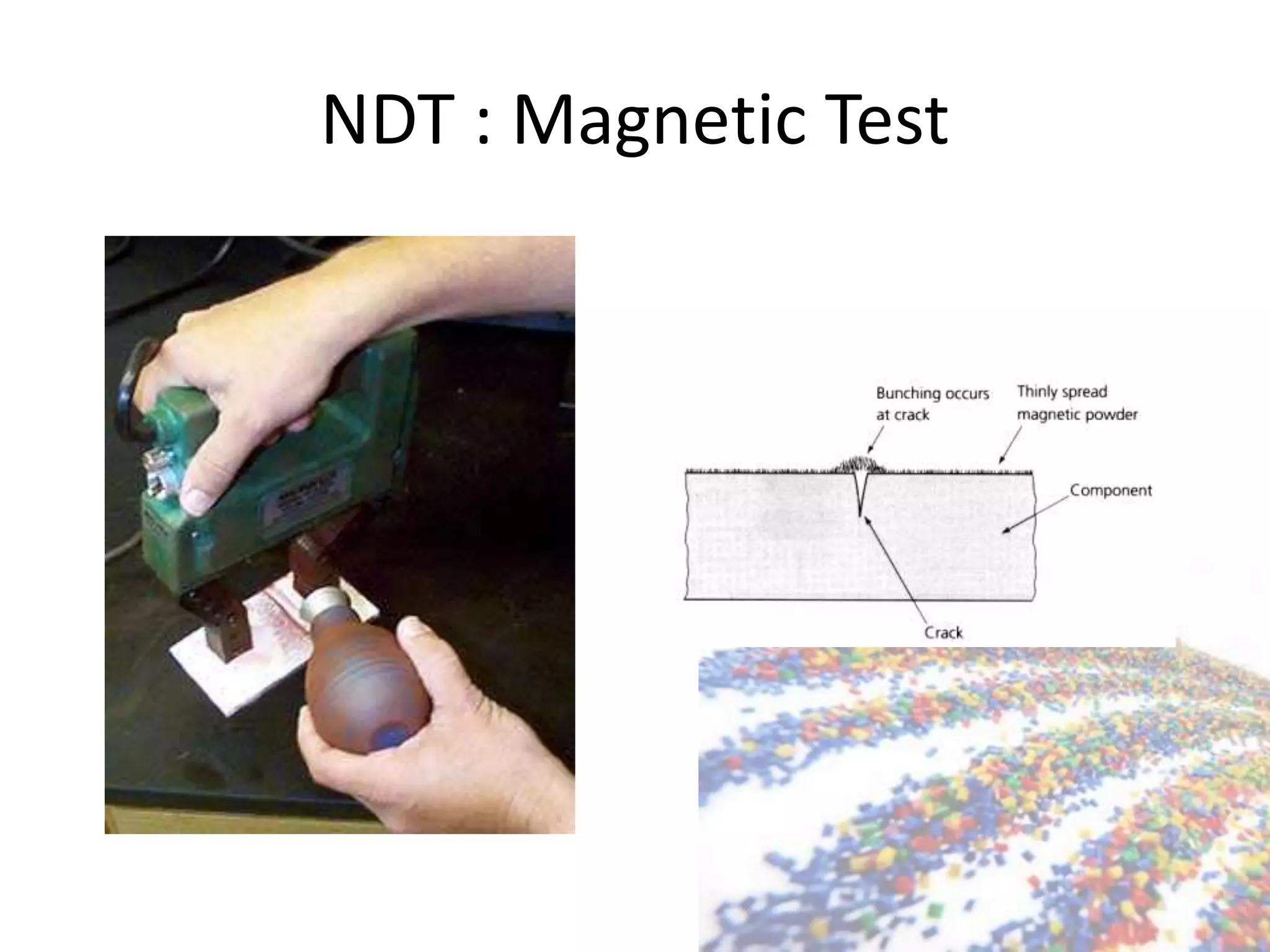
Penetration and magnetic testing methods for identifying surface defects in materials.
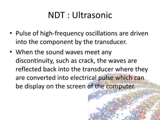
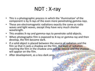
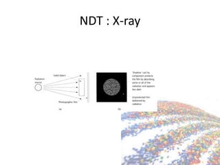
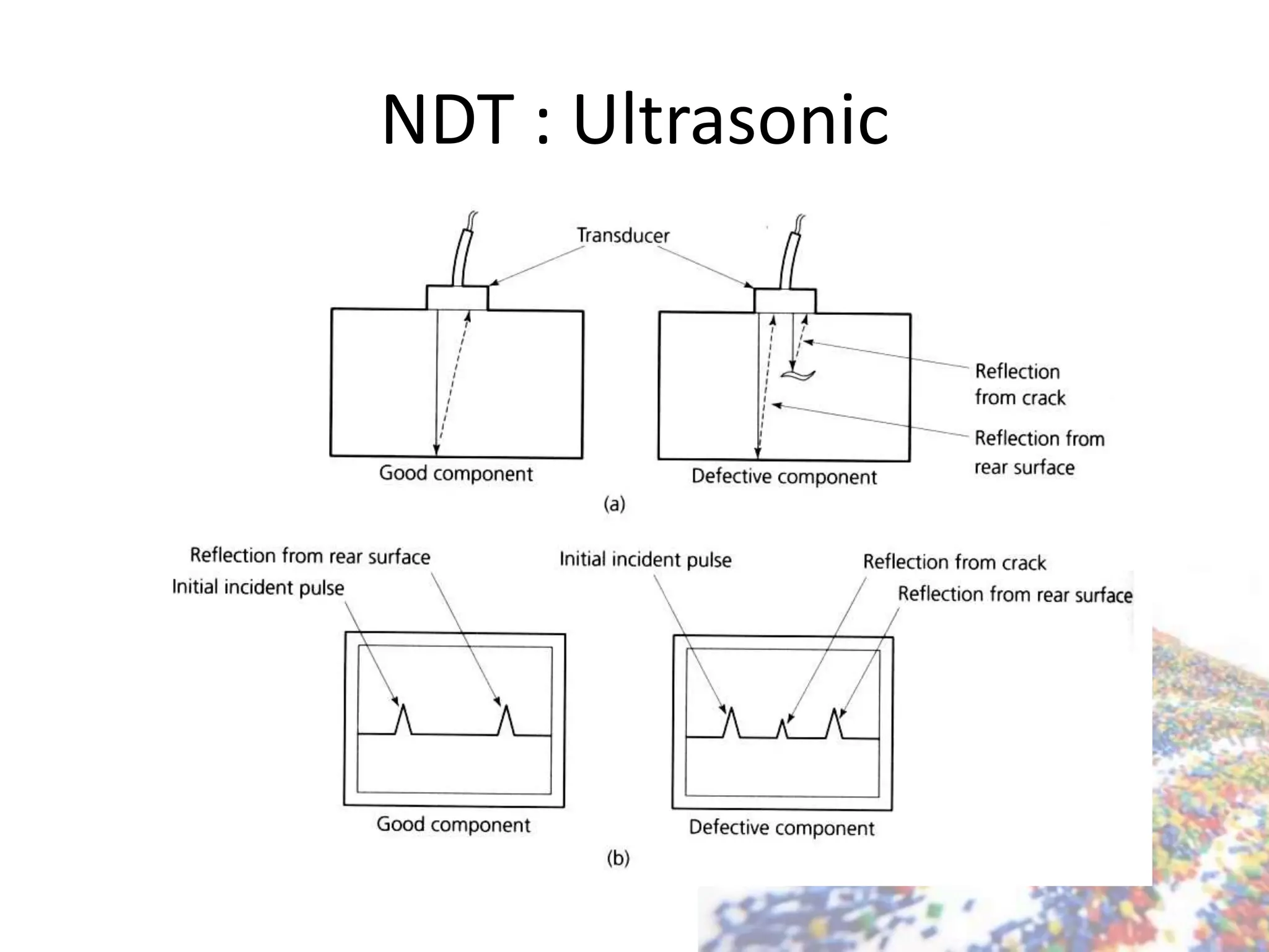
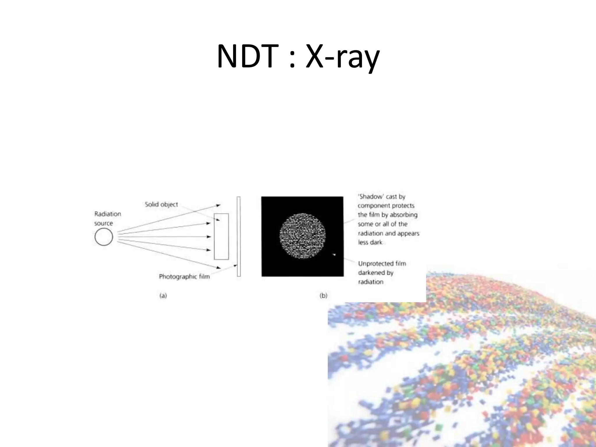
Ultrasonic and X-ray testing for material inspection; principles and applications described.


