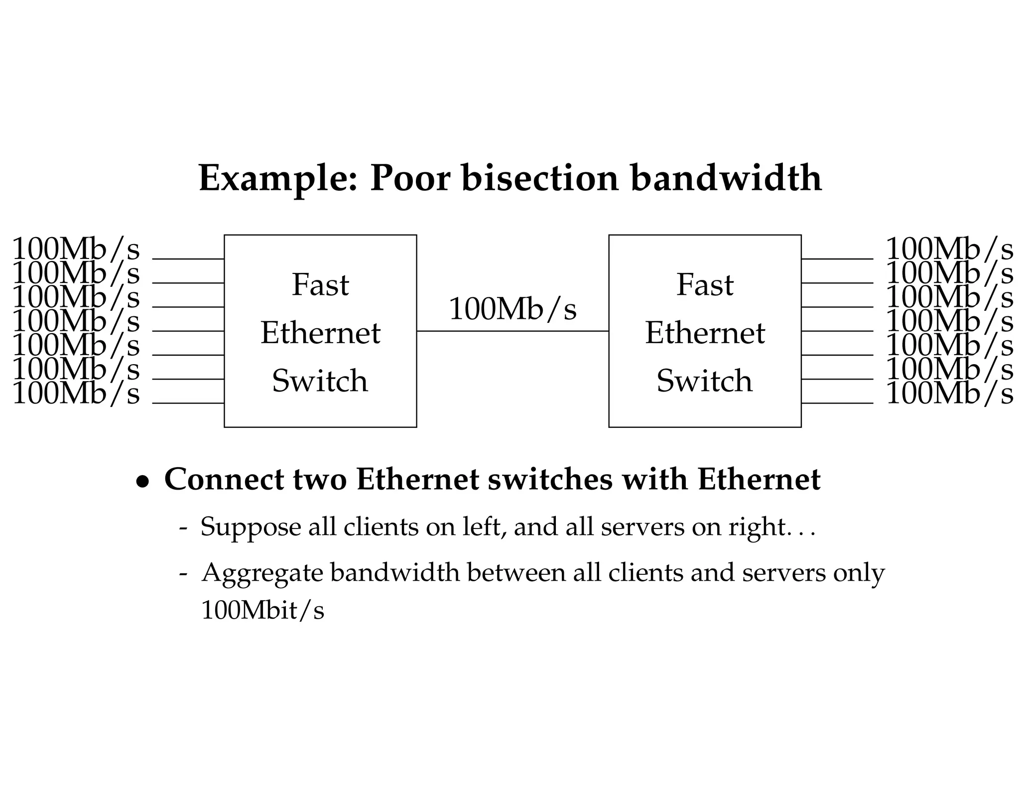
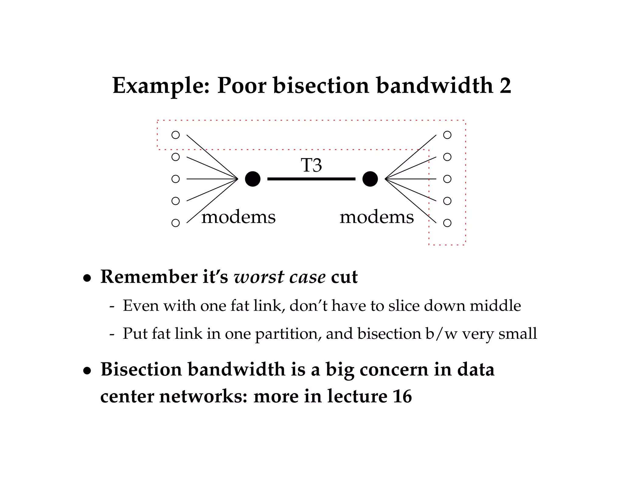
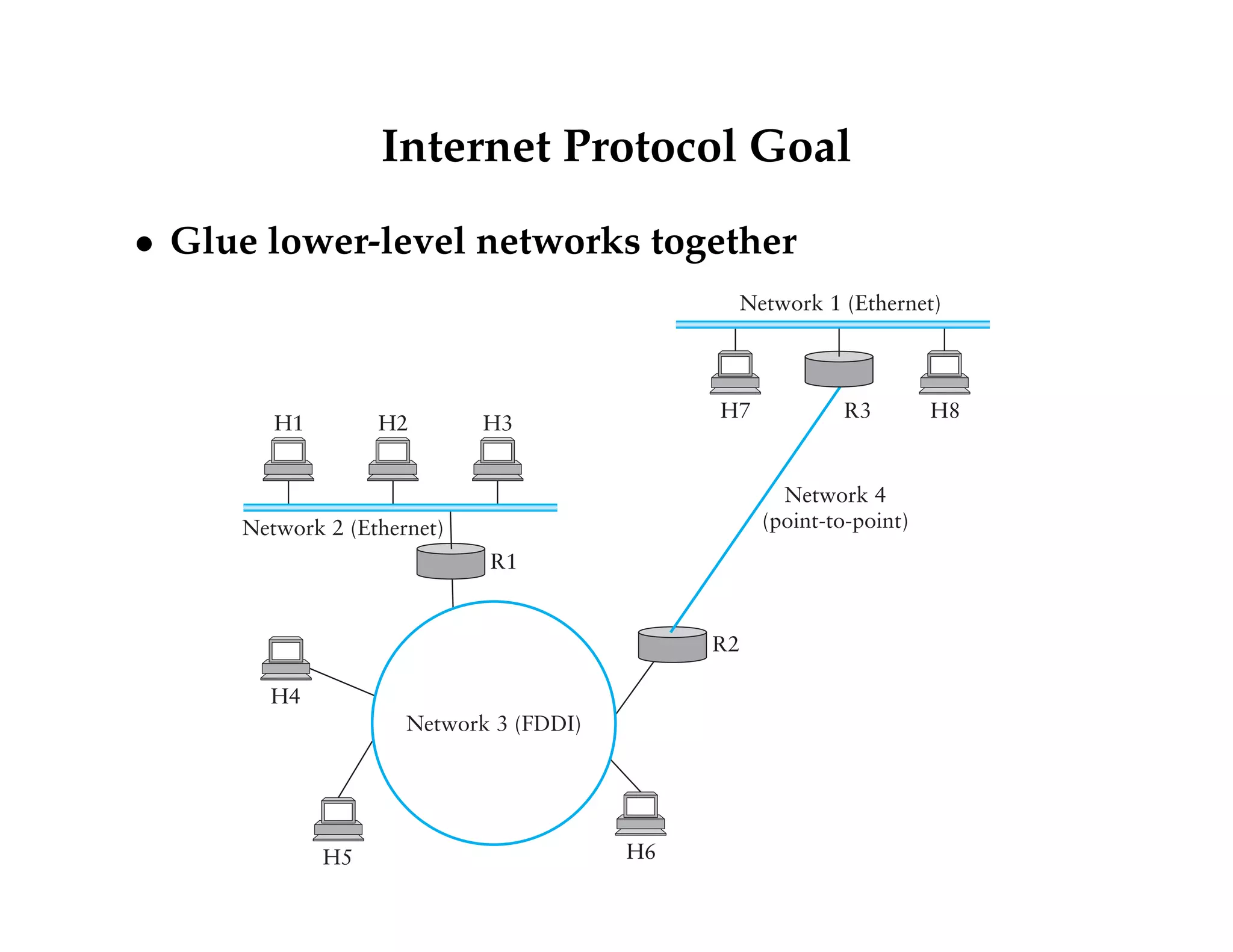
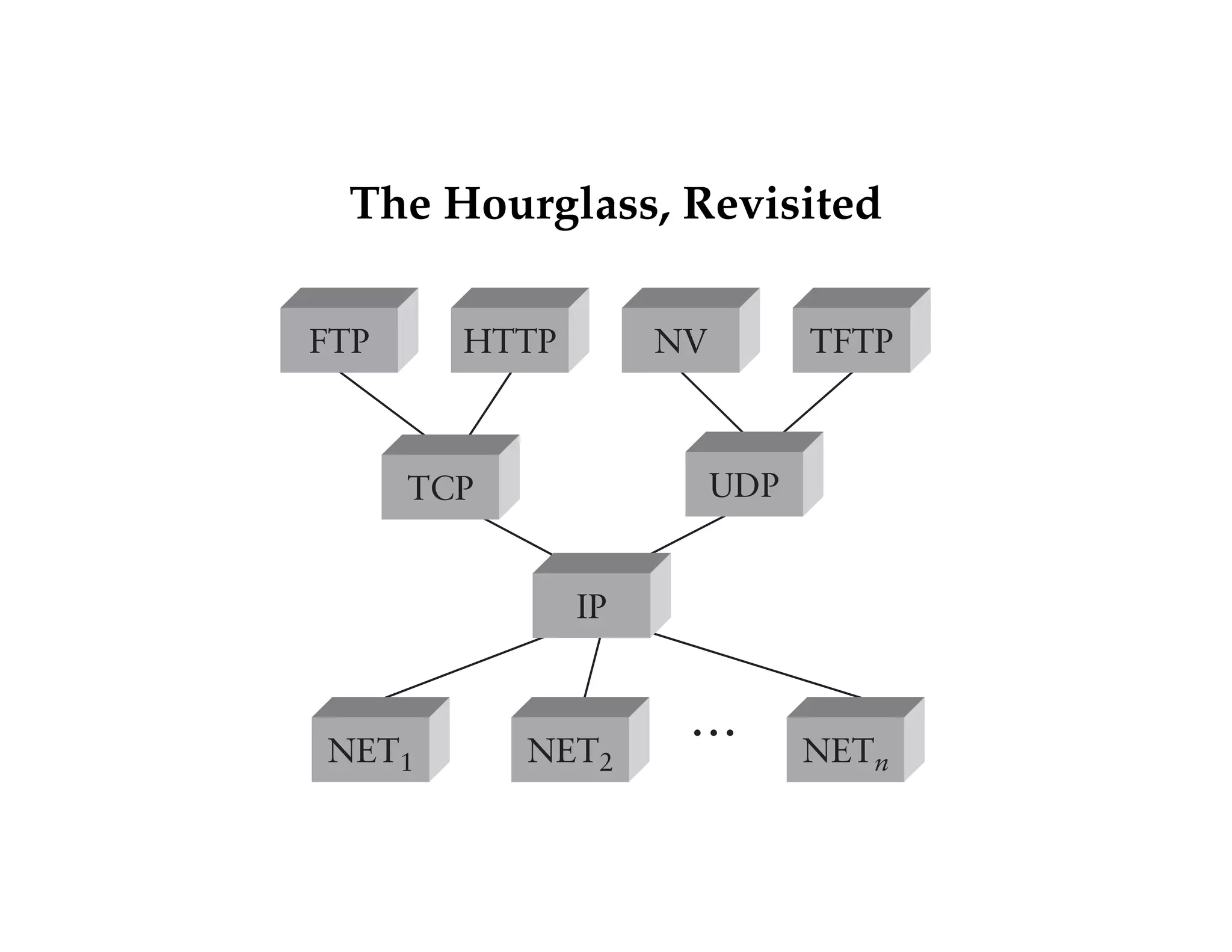
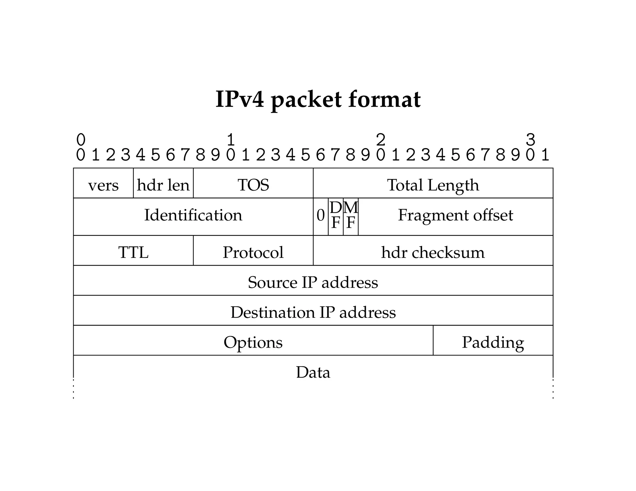
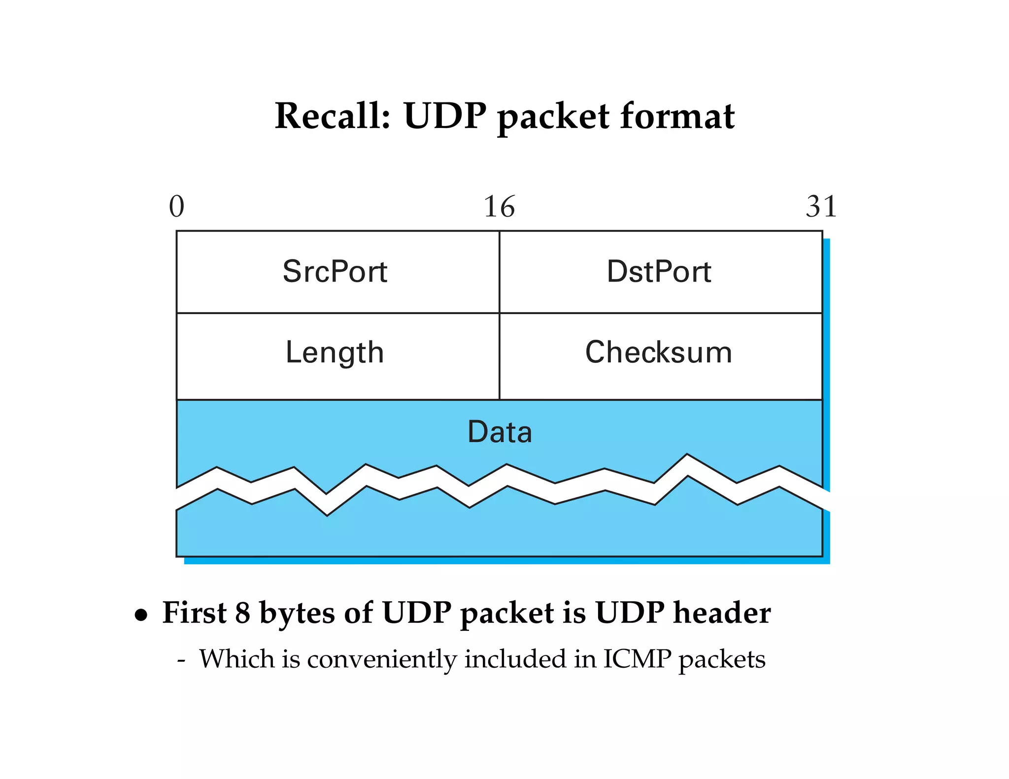
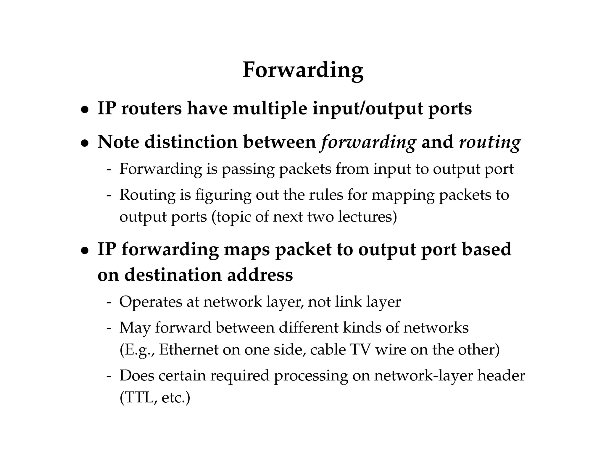
KEMBAR78
Computer network (12) | PDF
Lecture 4: IP, Forwarding, and Switch Fabrics
Overview 
 Internet Protocol (v4) 
- What it provides and its header 
- Fragmentation and assembly 
 IP Addresses 
- Format and assignment: class-A, class-B, CIDR 
- Mapping, translation, and DHCP 
 Packet forwarding, circuits, source routing 
 Switch fabrics 
 Bisection bandwidth
Internet Protocol Goal 
 Glue lower-level networks together 
H7 R3 H8 
R2 
H1 H2 H3 
R1 
Network 2 (Ethernet) 
H4 
H5 
Network 1 (Ethernet) 
H6 
Network 4 
(point-to-point) 
Network 3 (FDDI)
The Hourglass, Revisited 
HTTP NV TFTP 
… 
FTP 
TCP UDP 
IP 
NET1 NET2 NET 
n
Internet Protocol 
 Connectionless (datagram-based) 
 Best-effort delivery (unreliable service) 
- packets are lost 
- packets are delivered out of order 
- duplicate copies of a packet are delivered 
- packets can be delayed for a long time
IPv4 packet format 
0 1 2 3 
0 1 2 3 4 5 6 7 8 9 0 1 2 3 4 5 6 7 8 9 0 1 2 3 4 5 6 7 8 9 0 1 
vers hdr len TOS Total Length 
Identification DM Fragment offset 
0 F F 
TTL Protocol hdr checksum 
Source IP address 
Destination IP address 
Options Padding 
Data
IP header details 
 Routing is based on destination address 
 TTL (time to live) decremented at each hop (avoids loops) 
- TTL mostly saves from routing loops 
- But other cool uses: : : 
 Fragmentation possible for large packets 
- Fragmented in network if crosses link w. small frame size 
- MF bit means more fragments for this IP packet 
- DF bit says “don’t fragment” (returns error to sender) 
 Following IP header is “payload” data 
- Typically beginning with TCP or UDP header
Example Encapsulation 
Sending Receiving 
Application data 
Transport header 
IP header 
Link layer header
IPv4 packet format 
0 1 2 3 
0 1 2 3 4 5 6 7 8 9 0 1 2 3 4 5 6 7 8 9 0 1 2 3 4 5 6 7 8 9 0 1 
vers hdr len TOS Total Length 
Identification DM Fragment offset 
0 F F 
TTL Protocol hdr checksum 
Source IP address 
Destination IP address 
Options Padding 
TCP or UDP header 
TCP or UDP payload
Other IP Fields 
 Version: 4 (IPv4) for most packets, there’s also IPv6 
(lecture 12) 
 Header length (in case of options) 
 Type of Service (diffserv, we won’t go into this) 
 Protocol identifier (UDP: 17, TCP: 6, ICMP:1, why 
is TCP earlier?) 
 Checksum over the header 
 Let’s look at a packet with wireshark
Fragmentation  Reassembly 
 Each network has some maximum transmission 
unit (MTU) 
 Strategy 
- Fragment when necessary (MTU  size of Datagram) 
- Source host tries to avoid fragmentation 
When fragment is lost, whole packet must be retransmitted! 
- Re-fragmentation is possible 
- Fragments are self-contained datagrams 
- Delay reassembly until destination host 
- Do not recover from lost fragments
Fragmentation example 
H1 R1 R2 R3 H8 
R1 R2 R3 
ETH FDDI 
PPP IP (512) (512) 
PPP IP (512) 
PPP IP (376) 
ETH IP 
ETH IP (512) 
ETH IP 
(376) 
IP (1400) IP (1400) 
 Ethernet MTU is 1,500 bytes 
 PPP MTU is 576 bytes 
- R2 Must fragment IP packets to forward them
Fragmentation example 
(continued) 
 IP addresses plus ident field 
identify fragments belonging to 
same packet 
 MF (more fragments) bit is 1 in all 
but last fragment 
 Fragment size multiple of 8 bytes 
- Multiply offset field by 8 to get fragment 
position within original packet 
(a) 
Ident = x 
Start of header 
0 Offset = 0 
Rest of header 
1400 data bytes 
(b) 
Ident = x 
Start of header 
1 Offset = 0 
Rest of header 
512 data bytes 
Ident = x 
Start of header 
1 Offset = 64 
Rest of header 
512 data bytes 
Ident = x 
Start of header 
0 Offset = 128 
Rest of header 
376 data bytes
TCP Path MTU discovery 
 Problem: How does TCP know what MSS to use? 
- On local network, obvious, but for more distant machines? 
 Solution: Exploit ICMP—another protocol on IP 
- ICMP for control messages, not intended for buik data 
- IP supports DF (don’t fragment) bit in IP header 
- Set DF to get ICMP can’t fragment when segment too big 
 Can do binary search on packet sizes 
- But better: Base algorithm on most common MTUs 
- Common algorithm may underestimate slightly (better 
than overestimating and losing packet) 
- See RFC1191 for details 
 Is TCP a layer on top of IP?
IP Address Format, Translation, and DHCP
Format of IP addresses 
 Globally unique (or made to seem that way) 
 Hierarchical: network + host 
- Aggregating addresses saves memory in routers, simplifies 
routing (as we will see next lecture) 
 Originally, routing prefix embedded in address: 
7 24 
Network Host 
0 
(a) 
14 16 
Network Host 
1 0 
(b) 
21 8 
Network Host 
1 1 0 
(c) 
(Still hear “class A,” “class B,” “class C”) 
 Now, routing info on “CIDR” blocks, addr+prefix-len 
- E.g., 171.67.0.0/16
Translating IP to lower-level addresses 
 Map IP addresses into physical addresses 
- E.g., Ethernet address of destination host 
- Or Ethernet address of next hop router 
 Techniques 
- Encode link layer address in host part of IP address 
(option is available, but only in IPv6) 
- Each network node maintains a lookup table (link!IP) 
 ARP – address resolution protocol 
- Table of IP to link layer address bindings 
- Broadcast request if IP address not in table 
- Everybody learns physical address of requesting node (broadcast) 
- Target machine responds with its link layer address 
- Table entries are discarded if not refreshed
Need for Address Translation 
 Layer 2 (link) address names a hardware interface 
- E.g., my wireless ethernet 00:26:b0:f9:25:cf 
 Layer 3 (network) address names a host 
- E.g., www06.stanford.edu is 171.67.216.19 
- (lecture 8 will explain mapping from name to IP) 
 Details: 
- A single host can have multiple hardware interfaces, so 
multiple link layer addresses for a single network address 
- A node is asked to forward a packet to another IP address: 
out which hardware interface does it send the packet?
Arp Ethernet packet format 
0 8 16 31 
Hardware type = 1 ProtocolType = 0x0800 
HLen = 48 PLen = 32 Operation 
SourceHardwareAddr (bytes 0–3) 
SourceHardwareAddr (bytes 4–5) 
SourceProtocolAddr (bytes 2–3) 
SourceProtocolAddr (bytes 0–1) 
TargetHardwareAddr (bytes 0–1) 
TargetHardwareAddr (bytes 2–5) 
TargetProtocolAddr (bytes 0–3)
Internet Control Message Protocol (ICMP) 
 Echo (ping) 
 Redirect (from router to source host) 
 Destination unreachable (protocol, port, or host) 
 TTL exceeded (so datagrams don’t cycle forever) 
 Checksum failed 
 Reassembly failed 
 Cannot fragment 
 Many ICMP messages include part of packet that 
triggered them 
- Example: Traceroute
ICMP message format 
0 1 2 3 
0 1 2 3 4 5 6 7 8 9 0 1 2 3 4 5 6 7 8 9 0 1 2 3 4 5 6 7 8 9 0 1 
20-byte IP header 
(protocol = 1—ICMP) 
Type Code Checksum 
depends on type/code 
 Types include: 
- echo, echo reply, destination unreachable, time exceeded, . . . 
- See http://www.iana.org/assignments/icmp-parameters
Example: Time exceeded 
0 1 2 3 
0 1 2 3 4 5 6 7 8 9 0 1 2 3 4 5 6 7 8 9 0 1 2 3 4 5 6 7 8 9 0 1 
20-byte IP header 
(protocol = 1—ICMP) 
Type = 11 Code Checksum 
unused 
IP header + first 8 payload bytes 
of packet that caused ICMP to be generated 
 Code usually 0 (TTL exceeded in transit) 
 Discussion: How does traceroute work?
Recall: UDP packet format 
0 16 31 
SrcPort DstPort 
Length Checksum 
Data 
 First 8 bytes of UDP packet is UDP header 
- Which is conveniently included in ICMP packets
DHCP 
 Hosts need IP addrs for their network interfaces 
 Sometimes assign manually (but this is a pain) 
 Or use Dynamic Host Configuration Protocol 
- Client broadcasts DHCP discover message 
- One or more DHCP servers send back DHCP offer 
- Sent to offered IP address (client hasn’t accepted yet) 
- But sent to client’s Ethernet address (not broadcast) 
- Client picks one offer, broadcasts DHCP request 
- Server replies with DHCP ack 
 Discussion: why also a gateway and netmask?
IP Forwarding
Forwarding 
 IP routers have multiple input/output ports 
 Note distinction between forwarding and routing 
- Forwarding is passing packets from input to output port 
- Routing is figuring out the rules for mapping packets to 
output ports (topic of next two lectures) 
 IP forwarding maps packet to output port based 
on destination address 
- Operates at network layer, not link layer 
- May forward between different kinds of networks 
(E.g., Ethernet on one side, cable TV wire on the other) 
- Does certain required processing on network-layer header 
(TTL, etc.)
Big Picture 
Broadcast 
Communication 
Network 
Communication 
Network 
Virtual 
Circuit 
Switched 
Communication 
Network 
Circuit-switched Packet-switched 
Datagram
Physical Circuit Diversion: Old PSTN 
 A telephone number is a program 
 Number sets up a physical wire connection to 
another phone 
 Old phones used to click...
Virtual Circuit Switching 
0 
1 
2 
3 
0 
1 
11 
Switch 1 Switch 2 
2 
3 
0 
Switch 3 
1 
2 
3 
0 
1 
2 
3 
7 
Host A Host B 
 Explicit connection setup (and tear-down) phase 
- Establishes virtual-circuit ID (VCI) on each link 
 Each switch maintains VC table 
- Switch maps hin-link, in-VCIi ! hout-link, out-VCIi 
- Subsequent packets follow established circuit 
 Sometimes called connection-oriented model
Datagram switching 
2 
3 1 
0 
0 
1 3 
2 
0 
3 1 
2 
Switch 3 Host B 
Switch 2 
Host A 
Switch 1 
Host C 
Host D 
Host E 
Host F 
Host G 
Host H 
 No connection setup phase 
- Switches have routing table based on node addresses 
 Each packet forwarded independently 
 Sometimes called connectionless model
Source routing 
2 
3 1 
0 
0 
1 3 
2 
0 
3 1 
2 
0 
3 1 
2 
3 0 1 3 0 1 
0 1 3 
Switch 3 
Host B 
Switch 2 
Host A 
Switch 1 
 Simple way to do datagram switching (punt 
forwarding decisions to the sender)
Virtual Circuit Model 
 Typically wait full RTT for connection setup 
before sending first data packet 
+ Each data packet contains only a small identifier, 
making the per-packet header overhead small 
 If a switch or a link in a connection fails, the 
connection is broken and a new one needs to be 
established 
+ Connection setup provides an opportunity to 
reserve resources 
+ Packets to the same destination can use different 
circuits
Datagram Model 
+ There is no round trip time delay waiting for 
connection setup; a host can send data as soon as it 
is ready 
 Source host has no way of knowing if the network 
is capable of delivering a packet or if the 
destination host is even up 
+ It is possible to route around failures 
 Overhead per packet is higher than for the 
connection-oriented model 
 All packets to the same destination must use the 
same path
2-minute stretch
Switch Fabrics
Cut through vs. store and forward 
 Two approaches to forwarding a packet 
- Receive a full packet, then send it on output port 
- Start retransmitting as soon as you know output port, 
before you have even received the full packet (cut-through) 
 Cut-through routing can greatly decrease latency 
 Disadvantage: Can’t always send useful packet 
- If packet corrupted, won’t check CRC till after you started 
transmitting 
- Or if Ethernet collision, may have to send runt packet on 
output link, wasting bandwidth
Generic hardware switching architecture 
Control 
processor 
Switch 
fabric 
Output 
port 
Input 
port 
 Goal: deliver packets from input to output ports 
 Three potential performance concerns: 
- Throughput in terms of bytes/time 
- Throughput in terms of packets/time 
- Latency
Shared bus switch 
I/O bus 
Interface 1 
Interface 2 
Interface 3 
CPU 
Main memory 
 Shared bus – like your PC 
- NIC DMAs packet to memory over I/O bus 
- CPU examines pkt header, sends to dest NIC over bus 
- I/O bus is serious bottleneck 
- For small packets, CPU may be limited, too 
 Shared memory – similar, has memory bottleneck
Crossbar switch 
 One [vertical] bus per input interface 
 One [horizontal] bus per output interface 
 Can connect any input to any output 
- Trivially allows any input!output permutation 
- But, expensive for large number of inputs/outputs
Self-routing switches 
Switch 
2 
1 2 
Port 1 
Port 2 
 Idea: Build up switch out of 22 elements 
 Each packet contains a “self-routing header” 
- For each switch along the way, specifies the output 
 Must somehow compute a path when introducing packet 
- Is there more than one path to chose from? 
- Will path collide with another packet? 
 Easy to implement stages once path computed
Banyan networks 
 A Banyan network has exactly one path from any 
input port to a given ouput port 
- Example: Each stage can flip one bit of the port number 
 Easy to compute paths 
 Problem: Not all permutations can be routed 
- Might want 1 ! 0 and 7 ! 1, but both paths use same link 
 But: Can always route packets if sorted 
- Leads to batcher banyan networks 
- Batcher phase sorts packets before banyan
Example: Banyan network 
Switch on middle bit 
Swich on high bit Switch on low bit 
001 
011 
110 
111 
001 
011 
110 
111
Where to buffer? 
 At some point more than one input port will have 
packets for the same output port 
 Where do you buffer the packet? 
- Input port 
- Output port
Emerging technology: optical switches 
 Already analog optical repeaters deployed 
- Will amplify any signal 
- Can change your low-level transmission protocol w/o 
replacing repeaters 
 Could possibly do the same thing for switching 
- Microscopic mirrors can redirect light to different ports 
- (The ultimate cut-through routing) 
 Technology exists, but not widely deployed 
- Optical switch will not see packet headers 
- Instructions on where to send packet need to be out-of-band
Bisection Bandwidth
Bisection bandwidth 
 Can speak of the bandwidth between sets of ports 
- Bandwidth is maximum achievable aggregate bandwidth 
between the two sets 
 Bisection bandwidth is important property of network 
- Lowest possible bandwidth between equal-sized sets of ports 
- Or almost equal-sized if odd number of ports 
 A network with bad bisection bandwidth may offer 
poor behavior 
- Even if no conflict between input and output link utilization, 
may have internal bottlenecks reducing throughput
Example: Poor bisection bandwidth 
100Mb/s 100Mb/s 
Fast 
Ethernet 
Switch 
Fast 
Ethernet 
Switch 
100Mb/s 
100Mb/s 
100Mb/s 
100Mb/s 
100Mb/s 
100Mb/s 
100Mb/s 
100Mb/s 
100Mb/s 
100Mb/s 
100Mb/s 
100Mb/s 
100Mb/s 
 Connect two Ethernet switches with Ethernet 
- Suppose all clients on left, and all servers on right: : : 
- Aggregate bandwidth between all clients and servers only 
100Mbit/s
Example: Poor bisection bandwidth 2 
T3 
modems modems 
 Remember it’s worst case cut 
- Even with one fat link, don’t have to slice down middle 
- Put fat link in one partition, and bisection b/w very small 
 Bisection bandwidth is a big concern in data 
center networks: more in lecture 16
Overview 
 Internet Protocol (v4) 
- What it provides and its header 
- Fragmentation and assembly 
 IP Addresses 
- Format and assignment: class-A, class-B, CIDR 
- Mapping, translation, and DHCP 
 Packet forwarding, circuits, source routing 
 Switch fabrics 
 Bisection bandwidth 
 Next lecture: how TCP works

Computer network (12)

  • 1.
    Lecture 4: IP,Forwarding, and Switch Fabrics
  • 2.
    Overview InternetProtocol (v4) - What it provides and its header - Fragmentation and assembly IP Addresses - Format and assignment: class-A, class-B, CIDR - Mapping, translation, and DHCP Packet forwarding, circuits, source routing Switch fabrics Bisection bandwidth
  • 3.
    Internet Protocol Goal Glue lower-level networks together H7 R3 H8 R2 H1 H2 H3 R1 Network 2 (Ethernet) H4 H5 Network 1 (Ethernet) H6 Network 4 (point-to-point) Network 3 (FDDI)
  • 4.
    The Hourglass, Revisited HTTP NV TFTP … FTP TCP UDP IP NET1 NET2 NET n
  • 5.
    Internet Protocol Connectionless (datagram-based) Best-effort delivery (unreliable service) - packets are lost - packets are delivered out of order - duplicate copies of a packet are delivered - packets can be delayed for a long time
  • 6.
    IPv4 packet format 0 1 2 3 0 1 2 3 4 5 6 7 8 9 0 1 2 3 4 5 6 7 8 9 0 1 2 3 4 5 6 7 8 9 0 1 vers hdr len TOS Total Length Identification DM Fragment offset 0 F F TTL Protocol hdr checksum Source IP address Destination IP address Options Padding Data
  • 7.
    IP header details Routing is based on destination address TTL (time to live) decremented at each hop (avoids loops) - TTL mostly saves from routing loops - But other cool uses: : : Fragmentation possible for large packets - Fragmented in network if crosses link w. small frame size - MF bit means more fragments for this IP packet - DF bit says “don’t fragment” (returns error to sender) Following IP header is “payload” data - Typically beginning with TCP or UDP header
  • 8.
    Example Encapsulation SendingReceiving Application data Transport header IP header Link layer header
  • 9.
    IPv4 packet format 0 1 2 3 0 1 2 3 4 5 6 7 8 9 0 1 2 3 4 5 6 7 8 9 0 1 2 3 4 5 6 7 8 9 0 1 vers hdr len TOS Total Length Identification DM Fragment offset 0 F F TTL Protocol hdr checksum Source IP address Destination IP address Options Padding TCP or UDP header TCP or UDP payload
  • 10.
    Other IP Fields Version: 4 (IPv4) for most packets, there’s also IPv6 (lecture 12) Header length (in case of options) Type of Service (diffserv, we won’t go into this) Protocol identifier (UDP: 17, TCP: 6, ICMP:1, why is TCP earlier?) Checksum over the header Let’s look at a packet with wireshark
  • 11.
    Fragmentation Reassembly Each network has some maximum transmission unit (MTU) Strategy - Fragment when necessary (MTU size of Datagram) - Source host tries to avoid fragmentation When fragment is lost, whole packet must be retransmitted! - Re-fragmentation is possible - Fragments are self-contained datagrams - Delay reassembly until destination host - Do not recover from lost fragments
  • 12.
    Fragmentation example H1R1 R2 R3 H8 R1 R2 R3 ETH FDDI PPP IP (512) (512) PPP IP (512) PPP IP (376) ETH IP ETH IP (512) ETH IP (376) IP (1400) IP (1400) Ethernet MTU is 1,500 bytes PPP MTU is 576 bytes - R2 Must fragment IP packets to forward them
  • 13.
    Fragmentation example (continued) IP addresses plus ident field identify fragments belonging to same packet MF (more fragments) bit is 1 in all but last fragment Fragment size multiple of 8 bytes - Multiply offset field by 8 to get fragment position within original packet (a) Ident = x Start of header 0 Offset = 0 Rest of header 1400 data bytes (b) Ident = x Start of header 1 Offset = 0 Rest of header 512 data bytes Ident = x Start of header 1 Offset = 64 Rest of header 512 data bytes Ident = x Start of header 0 Offset = 128 Rest of header 376 data bytes
  • 14.
    TCP Path MTUdiscovery Problem: How does TCP know what MSS to use? - On local network, obvious, but for more distant machines? Solution: Exploit ICMP—another protocol on IP - ICMP for control messages, not intended for buik data - IP supports DF (don’t fragment) bit in IP header - Set DF to get ICMP can’t fragment when segment too big Can do binary search on packet sizes - But better: Base algorithm on most common MTUs - Common algorithm may underestimate slightly (better than overestimating and losing packet) - See RFC1191 for details Is TCP a layer on top of IP?
  • 15.
    IP Address Format,Translation, and DHCP
  • 16.
    Format of IPaddresses Globally unique (or made to seem that way) Hierarchical: network + host - Aggregating addresses saves memory in routers, simplifies routing (as we will see next lecture) Originally, routing prefix embedded in address: 7 24 Network Host 0 (a) 14 16 Network Host 1 0 (b) 21 8 Network Host 1 1 0 (c) (Still hear “class A,” “class B,” “class C”) Now, routing info on “CIDR” blocks, addr+prefix-len - E.g., 171.67.0.0/16
  • 17.
    Translating IP tolower-level addresses Map IP addresses into physical addresses - E.g., Ethernet address of destination host - Or Ethernet address of next hop router Techniques - Encode link layer address in host part of IP address (option is available, but only in IPv6) - Each network node maintains a lookup table (link!IP) ARP – address resolution protocol - Table of IP to link layer address bindings - Broadcast request if IP address not in table - Everybody learns physical address of requesting node (broadcast) - Target machine responds with its link layer address - Table entries are discarded if not refreshed
  • 18.
    Need for AddressTranslation Layer 2 (link) address names a hardware interface - E.g., my wireless ethernet 00:26:b0:f9:25:cf Layer 3 (network) address names a host - E.g., www06.stanford.edu is 171.67.216.19 - (lecture 8 will explain mapping from name to IP) Details: - A single host can have multiple hardware interfaces, so multiple link layer addresses for a single network address - A node is asked to forward a packet to another IP address: out which hardware interface does it send the packet?
  • 19.
    Arp Ethernet packetformat 0 8 16 31 Hardware type = 1 ProtocolType = 0x0800 HLen = 48 PLen = 32 Operation SourceHardwareAddr (bytes 0–3) SourceHardwareAddr (bytes 4–5) SourceProtocolAddr (bytes 2–3) SourceProtocolAddr (bytes 0–1) TargetHardwareAddr (bytes 0–1) TargetHardwareAddr (bytes 2–5) TargetProtocolAddr (bytes 0–3)
  • 20.
    Internet Control MessageProtocol (ICMP) Echo (ping) Redirect (from router to source host) Destination unreachable (protocol, port, or host) TTL exceeded (so datagrams don’t cycle forever) Checksum failed Reassembly failed Cannot fragment Many ICMP messages include part of packet that triggered them - Example: Traceroute
  • 21.
    ICMP message format 0 1 2 3 0 1 2 3 4 5 6 7 8 9 0 1 2 3 4 5 6 7 8 9 0 1 2 3 4 5 6 7 8 9 0 1 20-byte IP header (protocol = 1—ICMP) Type Code Checksum depends on type/code Types include: - echo, echo reply, destination unreachable, time exceeded, . . . - See http://www.iana.org/assignments/icmp-parameters
  • 22.
    Example: Time exceeded 0 1 2 3 0 1 2 3 4 5 6 7 8 9 0 1 2 3 4 5 6 7 8 9 0 1 2 3 4 5 6 7 8 9 0 1 20-byte IP header (protocol = 1—ICMP) Type = 11 Code Checksum unused IP header + first 8 payload bytes of packet that caused ICMP to be generated Code usually 0 (TTL exceeded in transit) Discussion: How does traceroute work?
  • 23.
    Recall: UDP packetformat 0 16 31 SrcPort DstPort Length Checksum Data First 8 bytes of UDP packet is UDP header - Which is conveniently included in ICMP packets
  • 24.
    DHCP Hostsneed IP addrs for their network interfaces Sometimes assign manually (but this is a pain) Or use Dynamic Host Configuration Protocol - Client broadcasts DHCP discover message - One or more DHCP servers send back DHCP offer - Sent to offered IP address (client hasn’t accepted yet) - But sent to client’s Ethernet address (not broadcast) - Client picks one offer, broadcasts DHCP request - Server replies with DHCP ack Discussion: why also a gateway and netmask?
  • 25.
  • 26.
    Forwarding IProuters have multiple input/output ports Note distinction between forwarding and routing - Forwarding is passing packets from input to output port - Routing is figuring out the rules for mapping packets to output ports (topic of next two lectures) IP forwarding maps packet to output port based on destination address - Operates at network layer, not link layer - May forward between different kinds of networks (E.g., Ethernet on one side, cable TV wire on the other) - Does certain required processing on network-layer header (TTL, etc.)
  • 27.
    Big Picture Broadcast Communication Network Communication Network Virtual Circuit Switched Communication Network Circuit-switched Packet-switched Datagram
  • 28.
    Physical Circuit Diversion:Old PSTN A telephone number is a program Number sets up a physical wire connection to another phone Old phones used to click...
  • 29.
    Virtual Circuit Switching 0 1 2 3 0 1 11 Switch 1 Switch 2 2 3 0 Switch 3 1 2 3 0 1 2 3 7 Host A Host B Explicit connection setup (and tear-down) phase - Establishes virtual-circuit ID (VCI) on each link Each switch maintains VC table - Switch maps hin-link, in-VCIi ! hout-link, out-VCIi - Subsequent packets follow established circuit Sometimes called connection-oriented model
  • 30.
    Datagram switching 2 3 1 0 0 1 3 2 0 3 1 2 Switch 3 Host B Switch 2 Host A Switch 1 Host C Host D Host E Host F Host G Host H No connection setup phase - Switches have routing table based on node addresses Each packet forwarded independently Sometimes called connectionless model
  • 31.
    Source routing 2 3 1 0 0 1 3 2 0 3 1 2 0 3 1 2 3 0 1 3 0 1 0 1 3 Switch 3 Host B Switch 2 Host A Switch 1 Simple way to do datagram switching (punt forwarding decisions to the sender)
  • 32.
    Virtual Circuit Model Typically wait full RTT for connection setup before sending first data packet + Each data packet contains only a small identifier, making the per-packet header overhead small If a switch or a link in a connection fails, the connection is broken and a new one needs to be established + Connection setup provides an opportunity to reserve resources + Packets to the same destination can use different circuits
  • 33.
    Datagram Model +There is no round trip time delay waiting for connection setup; a host can send data as soon as it is ready Source host has no way of knowing if the network is capable of delivering a packet or if the destination host is even up + It is possible to route around failures Overhead per packet is higher than for the connection-oriented model All packets to the same destination must use the same path
  • 34.
  • 35.
  • 36.
    Cut through vs.store and forward Two approaches to forwarding a packet - Receive a full packet, then send it on output port - Start retransmitting as soon as you know output port, before you have even received the full packet (cut-through) Cut-through routing can greatly decrease latency Disadvantage: Can’t always send useful packet - If packet corrupted, won’t check CRC till after you started transmitting - Or if Ethernet collision, may have to send runt packet on output link, wasting bandwidth
  • 37.
    Generic hardware switchingarchitecture Control processor Switch fabric Output port Input port Goal: deliver packets from input to output ports Three potential performance concerns: - Throughput in terms of bytes/time - Throughput in terms of packets/time - Latency
  • 38.
    Shared bus switch I/O bus Interface 1 Interface 2 Interface 3 CPU Main memory Shared bus – like your PC - NIC DMAs packet to memory over I/O bus - CPU examines pkt header, sends to dest NIC over bus - I/O bus is serious bottleneck - For small packets, CPU may be limited, too Shared memory – similar, has memory bottleneck
  • 39.
    Crossbar switch One [vertical] bus per input interface One [horizontal] bus per output interface Can connect any input to any output - Trivially allows any input!output permutation - But, expensive for large number of inputs/outputs
  • 40.
    Self-routing switches Switch 2 1 2 Port 1 Port 2 Idea: Build up switch out of 22 elements Each packet contains a “self-routing header” - For each switch along the way, specifies the output Must somehow compute a path when introducing packet - Is there more than one path to chose from? - Will path collide with another packet? Easy to implement stages once path computed
  • 41.
    Banyan networks A Banyan network has exactly one path from any input port to a given ouput port - Example: Each stage can flip one bit of the port number Easy to compute paths Problem: Not all permutations can be routed - Might want 1 ! 0 and 7 ! 1, but both paths use same link But: Can always route packets if sorted - Leads to batcher banyan networks - Batcher phase sorts packets before banyan
  • 42.
    Example: Banyan network Switch on middle bit Swich on high bit Switch on low bit 001 011 110 111 001 011 110 111
  • 43.
    Where to buffer? At some point more than one input port will have packets for the same output port Where do you buffer the packet? - Input port - Output port
  • 44.
    Emerging technology: opticalswitches Already analog optical repeaters deployed - Will amplify any signal - Can change your low-level transmission protocol w/o replacing repeaters Could possibly do the same thing for switching - Microscopic mirrors can redirect light to different ports - (The ultimate cut-through routing) Technology exists, but not widely deployed - Optical switch will not see packet headers - Instructions on where to send packet need to be out-of-band
  • 45.
  • 46.
    Bisection bandwidth Can speak of the bandwidth between sets of ports - Bandwidth is maximum achievable aggregate bandwidth between the two sets Bisection bandwidth is important property of network - Lowest possible bandwidth between equal-sized sets of ports - Or almost equal-sized if odd number of ports A network with bad bisection bandwidth may offer poor behavior - Even if no conflict between input and output link utilization, may have internal bottlenecks reducing throughput
  • 47.
    Example: Poor bisectionbandwidth 100Mb/s 100Mb/s Fast Ethernet Switch Fast Ethernet Switch 100Mb/s 100Mb/s 100Mb/s 100Mb/s 100Mb/s 100Mb/s 100Mb/s 100Mb/s 100Mb/s 100Mb/s 100Mb/s 100Mb/s 100Mb/s Connect two Ethernet switches with Ethernet - Suppose all clients on left, and all servers on right: : : - Aggregate bandwidth between all clients and servers only 100Mbit/s
  • 48.
    Example: Poor bisectionbandwidth 2 T3 modems modems Remember it’s worst case cut - Even with one fat link, don’t have to slice down middle - Put fat link in one partition, and bisection b/w very small Bisection bandwidth is a big concern in data center networks: more in lecture 16
  • 49.
    Overview InternetProtocol (v4) - What it provides and its header - Fragmentation and assembly IP Addresses - Format and assignment: class-A, class-B, CIDR - Mapping, translation, and DHCP Packet forwarding, circuits, source routing Switch fabrics Bisection bandwidth Next lecture: how TCP works