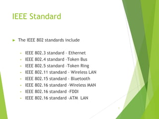
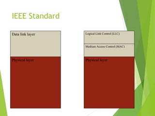
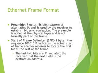
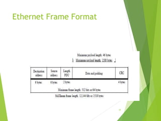
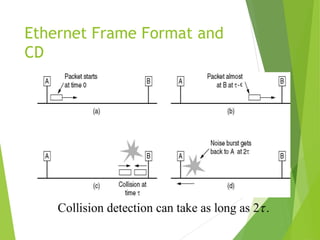
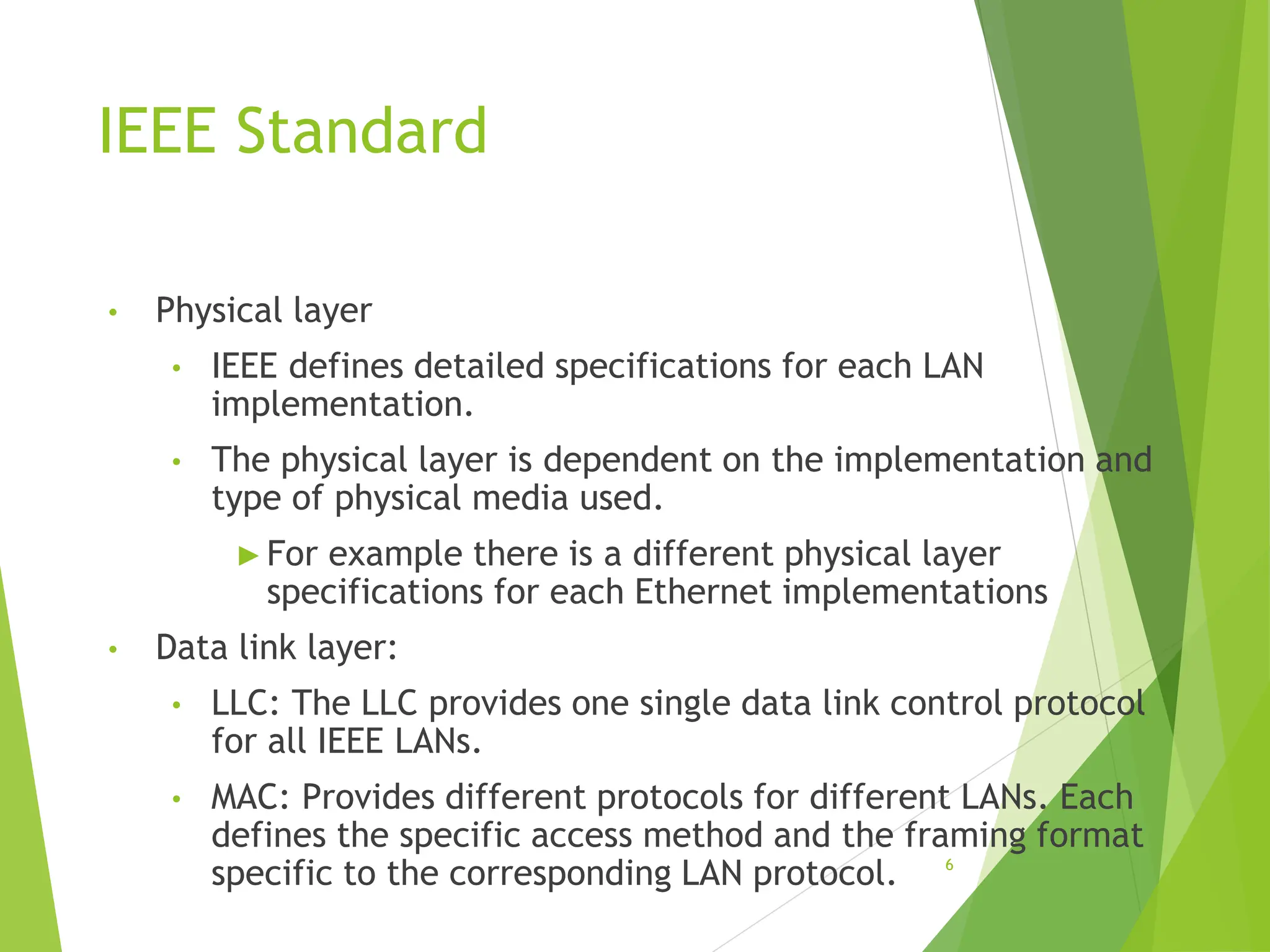
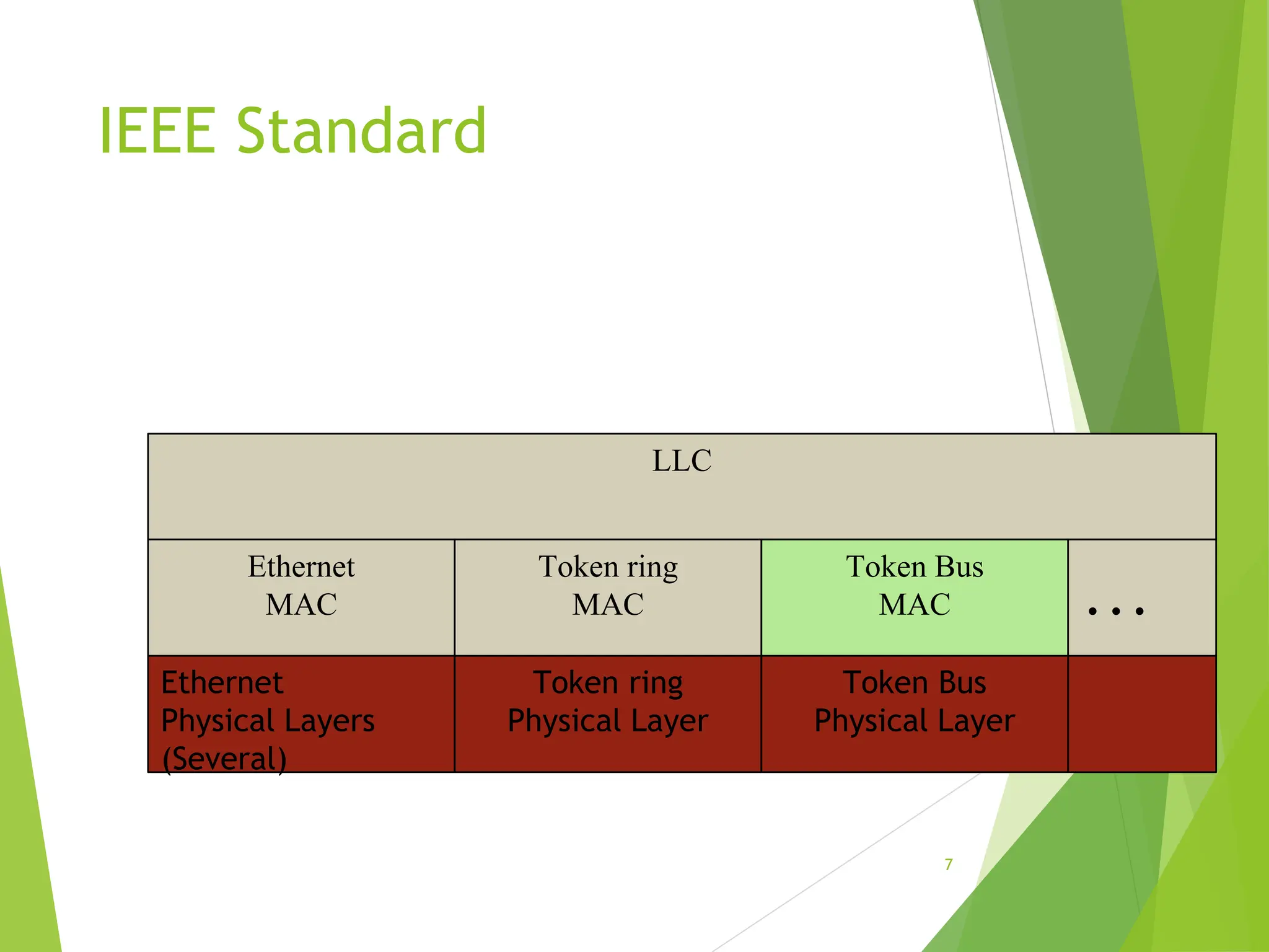
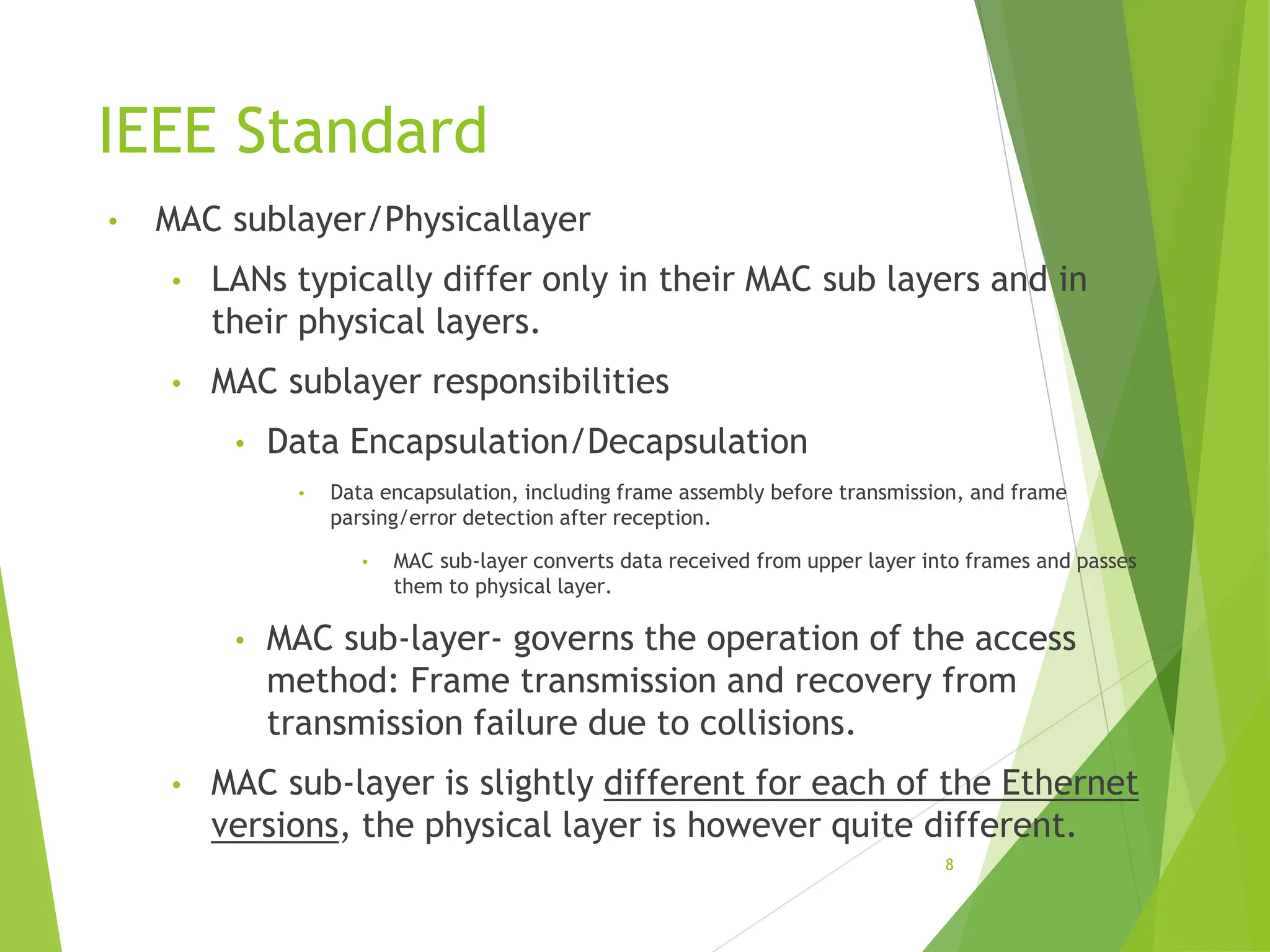
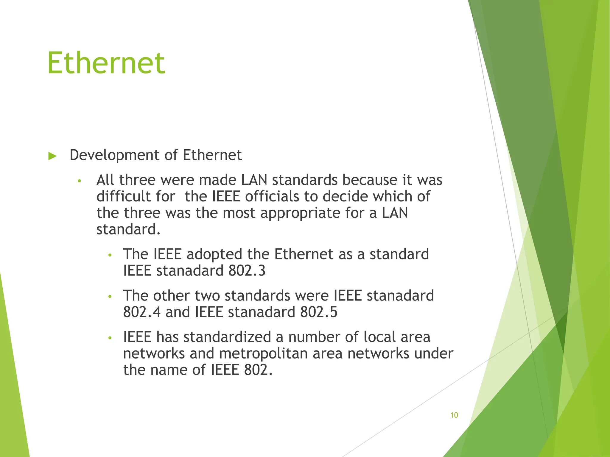
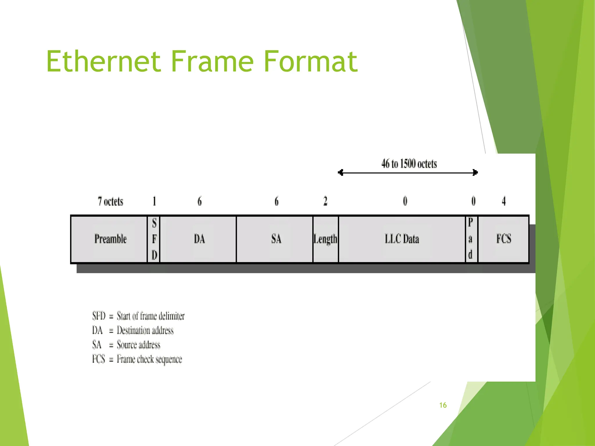
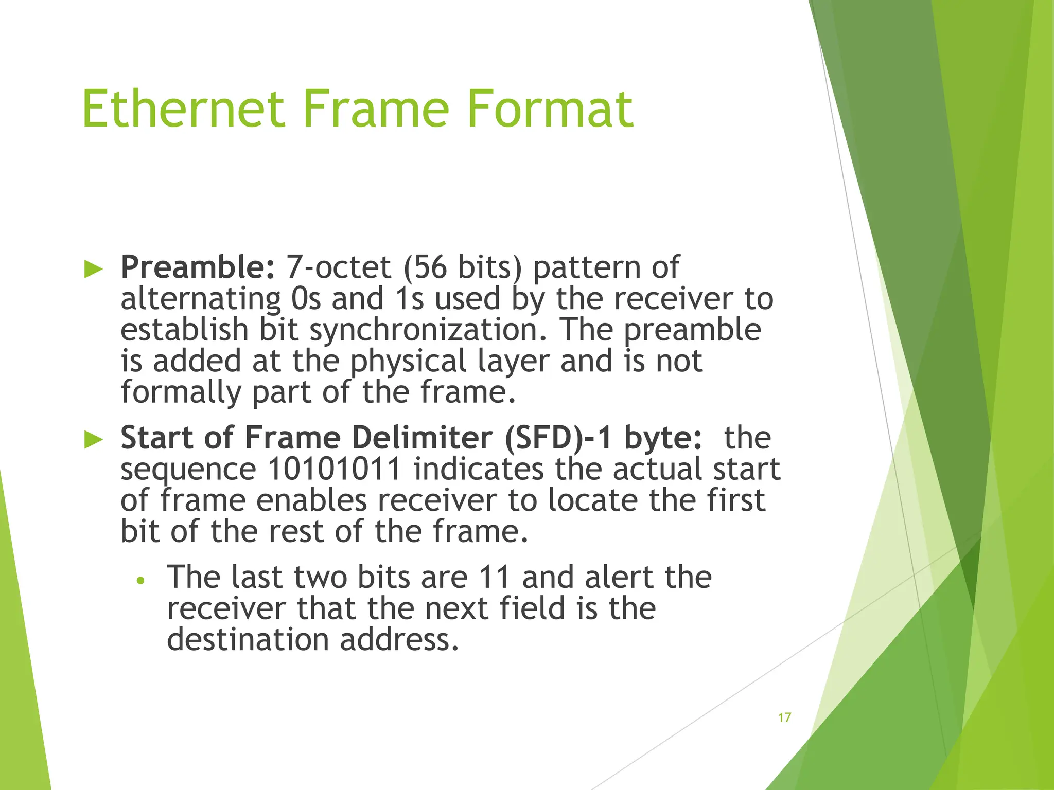
KEMBAR78
Computer Networks IEEE 802.3 standard-2021.pptx
1
Computer Networks
CSC 225
IEEE 802.3 Standard
INTRODUCTION
Source: Google images
3
IEEE Standard
► The IEEE 802 standards include
▪ IEEE 802.3 standard – Ethernet
▪ IEEE 802.4 standard –Token Bus
▪ IEEE 802.5 standard –Token Ring
▪ IEEE 802.11 standard – Wireless LAN
▪ IEEE 802.15 standard – Bluetooth
▪ IEEE 802.16 standard –Wireless MAN
▪ IEEE 802.16 standard –FDDI
▪ IEEE 802.16 standard –ATM LAN
IEEE Standard
• The data Link layer in the IEEE Standard is divided
into two sub layers:
4
IEEE Standard
5
Data link layer
Physical layer
Logical Link Control (LLC)
Medium Access Control (MAC)
Physical layer
IEEE Standard
• Physical layer
• IEEE defines detailed specifications for each LAN
implementation.
• The physical layer is dependent on the implementation and
type of physical media used.
►For example there is a different physical layer
specifications for each Ethernet implementations
• Data link layer:
• LLC: The LLC provides one single data link control protocol
for all IEEE LANs.
• MAC: Provides different protocols for different LANs. Each
defines the specific access method and the framing format
specific to the corresponding LAN protocol. 6
IEEE Standard
7
LLC
Ethernet
MAC
Token ring
MAC
Token Bus
MAC …
Ethernet
Physical Layers
(Several)
Token ring
Physical Layer
Token Bus
Physical Layer
IEEE Standard
• MAC sublayer/Physicallayer
• LANs typically differ only in their MAC sub layers and in
their physical layers.
• MAC sublayer responsibilities
• Data Encapsulation/Decapsulation
• Data encapsulation, including frame assembly before transmission, and frame
parsing/error detection after reception.
• MAC sub-layer converts data received from upper layer into frames and passes
them to physical layer.
• MAC sub-layer- governs the operation of the access
method: Frame transmission and recovery from
transmission failure due to collisions.
• MAC sub-layer is slightly different for each of the Ethernet
versions, the physical layer is however quite different.
8
Ethernet
► Development of Ethernet
• Robert Metcalfe in his PhD thesis researched on LAN
Technology.
• After Graduation he joined Xerox corporation and
worked with a group which implemented Ethernet
(1976).
• Later the concepts of Ethernet were written and
proposed to the IEEE as a standard for LANs. The
proposal was backed by Xerox, Intel and DEC.
• Two other proposals were presented to IEEE at
about the same time. One backed by General
motors and the other by IBM.
9
Ethernet
► Development of Ethernet
• All three were made LAN standards because it was
difficult for the IEEE officials to decide which of
the three was the most appropriate for a LAN
standard.
• The IEEE adopted the Ethernet as a standard
IEEE stanadard 802.3
• The other two standards were IEEE stanadard
802.4 and IEEE stanadard 802.5
• IEEE has standardized a number of local area
networks and metropolitan area networks under
the name of IEEE 802.
10
Traditional
Ethernet
MAC layer
11
12
Ethernet Standard
► Traditional Ethernet
• Uses bus/star topology
• Uses 1-persistent CSMA/CD.
• Defines 10Mbps Ethernet.
• It is typically used to connect PCs,
workstations, Printers, file servers and even
mainframes.
MAC LAYER
13
14
Issues
► MAC Layer Issues
► Frame Format
► Frame assembly
► Max and Min frame
► Addressing
► Address Format
► Address transmission
► Slot time
► Maximum Network length
15
Ethernet Frame Format
► The Ethernet frame contains seven fields.
► See the frame structure below.
16
Ethernet Frame Format
17
Ethernet Frame Format
► Preamble: 7-octet (56 bits) pattern of
alternating 0s and 1s used by the receiver to
establish bit synchronization. The preamble
is added at the physical layer and is not
formally part of the frame.
► Start of Frame Delimiter (SFD)-1 byte: the
sequence 10101011 indicates the actual start
of frame enables receiver to locate the first
bit of the rest of the frame.
• The last two bits are 11 and alert the
receiver that the next field is the
destination address.
18
Ethernet Frame Format
► Destination address: The Destination
address is 6 bytes and contains the
physical address of the destination station
for which frame is intended
► Source Address: The source address is
also 6 bytes and contains the physical
address of the Station that sent the frame
19
Ethernet Frame Format
► Length/Type:
• The field is defined as a length(IEEE) or type field(Original
ethernet).
• If the value of the field is less than 1518, it is a length field
and defines the length of the data field that follows.
► Provides a pointer to the boundary between the end of
data and CRC
• On the other hand if the value of this field is greater than
1536 it defines the type of the PDU packet (higher level
protocols ) that is encapsulated in the frame.
▪ Tells receiver what to do with the frame.
▪ Multiple network layer protocols may be in use on the
same machine
▪ The type specifies which process to give the frame to
20
Ethernet Frame Format
► LLC data: This field carries the data supplied by
upper layer protocols.
• It is a minimum of 46 and a maximum of 1500
bytes.
21
Ethernet Frame Format
► Pad: Octets added to ensure that frame is long
enough for proper CD operation
• There is always a minimum data and pad
length of 46 bytes i.e. if the data length is 0
bytes, the pad has 46 bytes. If the data field is
>= 46 bytes, the pad field reduces to zero
• This ensures a minimum frame size of 64
bytes (18 bytes header), which ensures that
collision detection works properly
► Frame check sequence: 32 bit CRC, based on all
fields except SFD and FCS. The FCS is generated over
the DA, SA, Length/Type, and Data fields.
Ethernet Frame Format
► Frame Assembly
• Whenever an end station MAC receives a transmit-
frame request with the accompanying address and
data information from the LLC sublayer, the MAC
begins the transmission sequence by transferring
the LLC information into the MAC frame buffer.
• The preamble and start-of-frame delimiter are
inserted in the PRE and SOF fields.
• The destination and source addresses are
inserted into the address fields.
• The LLC data bytes are counted, and the
number of bytes is inserted into the
Length/Type field.
22
Ethernet Frame Format
• Frame Assembly
• The LLC data bytes are inserted into the Data
field. If the number of LLC data bytes is less
than 46, a pad is added to bring the Data field
length up to 46.
• An FCS value is generated over the DA, SA,
Length/Type, and Data fields and is appended
to the end of the Data field.
• After the frame is assembled, actual frame
transmission will depend on whether the MAC is
operating in half-duplex or full-duplex mode.
23
24
Ethernet Frame Format
• Frame length:
• Minimum and maximum frame length
• The standard defines the minimum and
maximum length of a frame (without
preamble and SFD field)
• Maximum = as 1518 bytes
• Minimum = 64 bytes(512 bits).
• 802.3 standard allows for a variable length
of data transfer
Ethernet Frame Format
25
26
Ethernet Frame Format
• Frame length:
• Minimum and maximum frame length
▪ Reasons for having minimum frame length
▪ The minimum length restriction is required
for the correct operation of CSMAlCD
▪ To prevent a station from completing the
transmission of a short frame before it
detects collision (if it occurs).
▪ The sender should still be transmitting
when a noise burst (if collision occurs) gets
back to it.
Ethernet Frame Format and
CD
28
Ethernet Frame Format
► Addressing
• Each station on an Ethernet network has its
own network interface card.
• The NIC fits inside the station and provides the
station with a 6-byte(48 bits) physical address.
• It is normally written in hexadecimal notation
using a hyphen to separate bytes from each
other.
• Example: 07-01-02-01-2C-4B
29
Ethernet Frame Format
► Addressing
• A source address is usually unicast address- the
frame comes from only one station.
• The destination address however can be
unicast, multicast or broadcast.
30
Ethernet Frame Format
► Addressing
• The address length may be 16 or 48 bits- a
local implementation choice
• 48-bit addresses are globally assigned, while 16
bit addressees are locally assigned
• Global addresses are assigned centrally by
IEEE to ensure that no two stations
anywhere in the world have the same
global address = 7 * 1013 global addresses.
31
Ethernet Frame Format
► Addressing
• The 48 bit addresses are the hardware
addresses of the individual network interface
cards which connect devices to the network
• These addresses are used on the LAN to
identify the exact stations between which the
packet transfers are taking place
• These addresses are often referred to as
Ethernet address or MAC address
32
Ethernet Frame Format
► Addressing
• A broadcast or multicast facility is provided through
the use of first two (high order) bits of the address
field
• The high order bit of the destination address is a 0
for ordinary addresses and 1 for group addresses.
• xxxxxxx0 xxxxxxxx xxxxxxxx xxxxxxxx xxxxxxxx xxxxxxxx
• xxxxxxx1 xxxxxxxx xxxxxxxx xxxxxxxx xxxxxxxx xxxxxxxx
• A broadcast destination address is forty-eight 1s.
• 11111111 11111111 11111111 11111111 11111111 11111111
• Bit 46 (adjacent to High order bit) is used to
distinguish local from global addresses
Ethernet Frame Format
• 4A:30:10:21:1O:1A
• This is a unicast address because A in binary is
1010 (even).
• 47:20:1B:2E:08:EE
• This is a multicast address because 7 in binary
is 0111 (odd).
• FF:FF:FF:FF:FF:FF
• This is a broadcast address because all digits
are F's.
33
Ethernet Frame Format
► Address transmission
• The address is sent out on the line left to right
byte by byte.
• For each byte the least significant bit is sent
out first.
• How the address 47:20:1B:2E:08:EE is sent out
on the line
• 11100010 00000100 11011000 01110100
00010000 01110111
34
Access method
► Standard Ethernet uses 1-persistent CSMA/CD
► Slot time
• Slot time is defined as the time to send minimum
length frame;
• The slot time in Ethernet is defined in bits. It is the
time required for a station to send 512 bits (The
shortest possible frame).
• This means that the actual slot time depends on the
data rate;
• Slot time = minimum length frame(bits)/data
rate(bits/sec)
• For traditional 10-Mbps Ethernet it is 51.2 μs.
35
Access method
► Slot time and collision
• The sender needs to be aware of the collision before
it has sent the entire frame(512 bits).
• Slot time = maximum time to detect collision
• = to twice the signal propagation time
between the two most-distant stations
on the network .
• It means that the slot time is dependent on the
propagation speed of the signal in the particular
medium.
• The round-trip time plus the time required
to send the jam sequence should be less than
the time needed for the sender to send the
minimum frame, 512 bits. 36
Access method
► Slot time and maximum network length
• Speed = Distance/Time & Time = Distance/Speed
• Slot time = (MaxLength * 2)/ PropagationSpeed;
• MaxLength = PropagationSpeed * SlotTime/2
37
Access method
► Slot time and maximum network length
• MaxLength = PropagationSpeed * SlotTime/2
• Longer minimum frame lengths translate to
longer slot times and larger collision diameters;
• Shorter minimum frame lengths correspond to
shorter slot times and smaller collision
diameters.
• Tradeoff between impact of collision recovery and
the need to accommodate reasonable network sizes.
38
Access method
► Slot time and maximum network length
• In most transmission media, the signal propagates
at 2.0 x 10⁸ rn/s
• MaxLength = PropagationSpeed * SlotTime/2
• Theoretical MaxLength = 5200 m for standard
ethernet
• = (2.0 x 108 * 51.2
*10-6 )/2
= (2.0* 51.2 * 102)/2
= 5120 m (≈ 5200 m)
► Considering the delay times in repeaters and
interfaces, and the time required to send the
jam sequence, Max length = 2500 m.
39
Ethernet
Evolution
MAC layer
40
Ethernet
Ethernet
evolution
Traditional
Ethernet
(10Mbps)
Fast Ethernet
(100Mbps)
Gigabit
Ethernet
(1Gbps)
Ten Gigabit
Ethernet
(10Gbps)
41
42
Ethernet Networks
► Ethernet Evolution
• The original Ethernet created in 1976 at Xerox’s
Palo Alto research center has since evolved.
• Ethernet has gone through a four-generation
evolution during the last few decades
• Standard/Traditional Ethernet: The original
Ethernet had a data rate of 10Mbps
• Fast Ethernet operates at 100Mbps
• Gigabit Ethernet Operates at 1Gbps
• 10 gigabit Ethernet Operates at 10Gbps
• 100 gigabit Ethernet Operates at 100Gbps
43
Ethernet Networks
• We discuss the ideas behind the evolution
• Bridged Ethernet
• Switched Ethernet
44
Bridged Ethernet
45
Bridged Ethernet
► The first step in the evolution was division of the
LAN by bridges.
► Effect of Bridges on the LAN:
• Raising the bandwidth: A bridge divides a
network into two or more segments, each
independent. It reduces the number of stations
sharing the capacity of the segment. Results in
a gain of more bandwidth for each segment.
• Separating collision domains: gives rise to
smaller collision domains, reducing the
probability of collisions.
46
Bridged LAN
Bridge operation
47
Switched Ethernet
► The next step was the evolution from bridged Ethernets to Switched
Ethernets .
► The switched Ethernets were an extension of the idea of a bridged
LAN to an N-port bridge. This led to even faster Ethernet.
• A layer 2 switch is an N-port bridge with additional sophistication
that allows faster handling of frames(switching, cut through etc).
► Effect of switches on the LAN:
• Increased bandwidth: The switch divides a network into N
independent segments where N is the number of stations in the
LAN. Bandwidth shared only between the station and the switch.
• Single user per collision domain: Gives rise to N collision domains
with one user per segment, reducing the probability of collisions
even further.
Switched LAN
48
49
Switched Ethernet
► The next step was the evolution from switched
Ethernet to full duplex Switched Ethernet.
► In full duplex switched Ethernet, instead of using
one link, uses two links between the station and
the switch; one to send and one to receive. This
led to even faster Ethernet.
► Effect of full duplex switches on the LAN:
• Doubles capacity of each collision domain:
Station can send and receive at the same time
in contrast to the half duplex Ethernets(10
Base5 and 10Base2).
50
Switched Ethernet
► In full duplex switched Ethernet there is no need
for CSMA/CD access method.
• Each station is connected via two separate
links.
• Each link is a point to point dedicated path
between the station and the switch.
• Station can send and receive simultaneously.
• No possibility of collision.
• The carrier sense and collision detection
functionality can be switched off.
51
Switched Ethernet
► The backoff feature which contributes to reduced
performance is mainly avoided and increased
performance is achieved
• The links however may still operate in half
duplex mode (backward compatibility)
• It is possible to run a port connection in full
duplex mode
Fast Ethernet
MAC layer
52
53
Fast Ethernet
► Fast Ethernet
• To allow for an increased speed of transmission, the Ethernet
protocol has developed a new standard to provide low cost Ethernet
compatible LAN, operating at 100Mbps
• Fast Ethernet is a collective term for a number of Ethernet
standards that carry traffic at 100Mbps.
• The Standard is referred to as 100Base-T
• This is commonly called Fast Ethernet.
54
Fast Ethernet
► Fast Ethernet
• Fast Ethernet was required to provide backward compatibility with
earlier Ethernet networks, including the existing IEEE 802.3 frame
format and error-detection procedures, plus all applications and
networking software running on the 10-Mbps networks.
• Fast Ethernet is similar to 10Mbps Ethernet in many ways
• MAC sub-layer is untouched
• CSMA/CD is the access method
• Full Duplex Fast Ethernet does not need CSMA/CD. But
implementation keeps CSMA/CD for backward
compatibility with traditional Ethernet.
• Frame format
• Minimum and maximum frame lengths
• Addressing
• The only difference is in the slot time and maximum network length.
55
Fast Ethernet
• Fast Ethernet
• Slot time and maximum network length
• At 100 Mbps:
• Slot time = 5.12 μs . A minimum-length frame can be
transmitted in approximately one-tenth (1/10) of the defined
slot time.
• Signal propagation velocity is essentially constant for all
transmission rates.
• The time required to transmit a frame is inversely related
to the transmission rate
• If collision occurs during the transmission (of minimum frame) it
would not be detected by the transmitting stations
• This means that the maximum network diameters specified for
10-Mbps networks could not be used for 100-Mbps networks.
56
Fast Ethernet
• Fast Ethernet
• Slot time and maximum network length
• At 100 Mbps:
• The solution for Fast Ethernet was to reduce the
maximum network diameter by approximately a factor of
10 while retaining the minimum frame length.
• Maximum network length = a little more than 200 meters.
Theoretical maximum is 512 m.
• MaxLength = PropagationSpeed * SlotTime/2
• Theoretical MaxLength = 512 m for fast ethernet
• Considering the delay times in repeaters and
interfaces, and the time required to send the jam
sequence, Max length = 250 m.
Gigabit Ethernet
MAC layer
57
58
Gigabit Ethernet
► One of the more recent developments in
the Ethernet standard is a protocol that
has a transmission speed of 1 Gbps.
► Describes various technologies for
transmitting Ethernet packets at a rate of
1Gbps.
► It can be used with both fiber optic
cabling and copper.
59
Gigabit Ethernet
► All configurations are point-to-point rather than
multi-drop as in the traditional Ethernet.
• Compatible with 10BASE-T and 100BASE-T
preserving a smooth migration path
60
Gigabit Ethernet
► Gigabit Ethernet while defining a new medium and transmission
specification, retains the same (as in 10Mbps and 100Mbps)
▪ CSMA/CD
▪ Frame format
► Addressing
• The aim was to keep MAC sub-layer untouched - not possible
► Gigabit Ethernet supports two different modes of operation: full
duplex and half duplex.
• Half duplex using CSMA/CD. Uses a hub rather than a switch.
Simulates the multi-drop cable in traditional Ethernet.
Complicated and not in use.
• Full Duplex with no need for CSMA/CD: “Normal mode”:
Almost all implementations use the full duplex approach
61
Gigabit Ethernet
• Half duplex operation
• Slot time and maximum network length
• At 1000 Mbps:
• Slot time = 0.512 μs. A minimum-length frame can be transmitted in
approximately one-hundredth (1/100) of the defined slot time;
• If collision occurs during the transmission (of minimum frame) it
would not be detected by the transmitting stations
• This means that the maximum network diameter specified for 100-
Mbps networks could not be used for 1000-Mbps networks.
62
Gigabit Ethernet
• Half duplex operation
• Slot time and maximum network length
• At 1000 Mbps:
• The solution for Gigabit Ethernet was to retain the maximum
network diameter same as 100-Mbps networks while
increasing the minimum frame length.
• reducing network diameter further by a factor of 10 to
20m impractical
► By adding a variable-length non data extension field to frames
that are shorter than the minimum length (the extension field
is removed during frame reception).
63
Gigabit Ethernet
► Half duplex operation
• Enhancements to the basic CSMA/CD scheme
• Carrier extension:
• Frame Bursting
• These features extend the radius of the
network for gigabit ethernet over copper
cabling. They are added to sustain the
CSMA/CD protocol.
64
Gigabit Ethernet
► Half duplex operation
• Carrier extension:
• Sending hardware to add its own padding to
a normal MAC frames to extend a frame to
520 bytes.
• This is so that the length of a transmission
is longer than the propagation time at
1Gbps
• Receiving hardware removes the padding.
Gigabit Ethernet
65
66
Gigabit Ethernet
► Half duplex operation
• Frame Bursting
• Another change to the Ethernet CSMA/CD
transmit specification was the addition of
frame bursting for gigabit operation.
• Allows sender to transmit a short sequence (a
burst) of multiple frames equal to
approximately 5.4 maximum-length frames in a
single transmission without relinquishing
control of the medium.
• Avoids the overhead of carrier extension when
a single station has a number of small frames
ready to send
67
Gigabit Ethernet
► Half duplex operation
• Frame Bursting
• If the length of the first frame is less than the
minimum frame length, an extension field is
added to extend the frame length.
• Subsequent frames in a frame-burst sequence
do not need extension fields, and a frame
burst may continue as long as the burst limit
has not been reached.
• If the burst limit is reached after a frame
transmission has begun, transmission is allowed
to continue until that entire frame has been
sent.
Gigabit Ethernet
68
69
Gigabit Ethernet
► Full duplex operation
• Full-duplex operation is an optional MAC capability that
allows simultaneous two-way transmission over point-to-
point links.
• With a switching hub which provides dedicated access
to the medium:
• Involves no media contention, no collisions, no need to
schedule retransmissions, and no need for extension bits on
the end of short frames.
• Since no contention is possible, the CSMA/CD protocol is
not used
• Carrier extension and frame bursting is not needed
70
Gigabit Ethernet
► Full duplex operation
• Data transmission and reception can occur simultaneously
without interference and with no contention for shared
medium.
• All lines are buffered so each computer can send frames
whenever it wants. No need to sense the channel
because contention is not possible.
• On the line between a computer and a switch, the
computer is the only possible sender on that line to the
switch and the transmission succeeds even if the switch
is currently sending a frame to the computer because
the line is full duplex.
• Each link supports full-rate, simultaneous, two-way
transmission
71
Gigabit Ethernet
► Full duplex operation
• Transmission can usually begin as soon as frames are ready
to send. The only restriction is that there must be a
minimum-length interframe gap between successive frames
72
Gigabit Ethernet
73
Gigabit Ethernet
► Full duplex operation
• Flow control
• Full-duplex operation requires concurrent implementation of the
optional flow-control capability that allows a receiving node
(switch or station) that is becoming congested to request the
sending node (such as a file server) to stop sending frames for a
selected short period of time (pause time).
• The receiving device sets timer for specified pause time and
stops sending data frames. Resumes sending frames when
timer expires.
• Control is MAC-to-MAC through the use of a pause frame that is
automatically generated by the receiving MAC.
• Device can send overlapping pause packets. A pause packet
cancels the previous pause packet. Receiver sets timer to the new
pause period.
• For example, if the congestion is relieved before the requested
wait has expired, a second pause frame with a zero time-to-wait
value can be sent to request resumption of transmission.
74
Gigabit Ethernet
75
Gigabit Ethernet
► Full duplex operation
• Flow control
• The MAC control sublayer is added between LLC and MAC
sublayers.Data link layer now has three sublayers: LLC, MAC
control and MAC
• MAC control is an optional sublayer; implementation left to
manufacturer.
• The MAC control sublayer provides error and flow control. Special
MAC control packets are inserted between packets coming from
upper layers.
• MAC control packet encapsulated in a MAC frame. Should be
minimum size packet(46 bytes). MAC control packet contains two
byte code with value 000116 and a 44-byte pause time (a factor of
the time slot) + padding if any.
• Currently only one MAC control packet is defined. The Pause
packet.
Ethernet Physical layer
76
Ethernet
► Ethernet Components
• There are several ways to connect devices
• A PC connects to the Cable through some hardware
• A transceiver attaches directly to network cable
• The transceiver communicates with the PC using
a transceiver cable.
77
Ethernet
► Ethernet Components
• The transceiver cable connects to the PC through a
Network interface card (NIC) installed in the PC.
• The NIC contains the logic necessary to:
• Buffer data and move it between the
transceiver cable and the PC’s memory.
• Do error checking, create frames, determine
when to transmit (after collisions occur) and
recognize frames destined for its PC..
• The NIC performs the functions appropriate for the
MC layer protocol.
• The NIC also relieves the PC’s processor from theses
tasks and allows it to attend to typical PC activities.
78
79
Ethernet
► Ethernet cabling specification
• IEEE 802.3 committee responsible for defining
alternative physical configurations
• The standard dictates the maximum length of a
segment, the type of cable, the type of tap or
connection, and the connection spacing
• Each cabling option carries with it a different set of
physical layer constraints (e.g., max. segment size,
nodes/segment, etc.)
• To distinguish the various implementations, the
committee has developed a concise notation.
• <data rate><Signaling method><Max segment length>
• in Mbps Base(baseband) rounded to
100m
Ethernet
► Ethernet cabling specification
• There are several different variations of the Ethernet
standard as defined by IEEE 802.3 They differ by
• Medium used in a segment
• The maximum segment length
• The number of stations that can connect to the
segment
• The data rates
• Examples:
• 10 Base5- 10 Mbps, Baseband,500m Maximum length
• 10 Base2- 10 Mbps, Baseband,200m Maximum length
80
Physical layer
Traditional Ethernet
81
82
Traditional Ethernet Cabling
Options
► Traditional Ethernet
• Defines four different implementations for the
10Mbps Ethernet.
Ethernet Cabling Options
•Traditional Ethernet implementations
•10Base5 (Bus, Thick coaxial)
•10Base2 (Bus,Thin Coaxial)
•10Base-T (Star , UTP)
•10Base-F (Star, Fiber)
83
84
Ethernet Cabling Options
85
Ethernet- 10Base5
Ethernet- 10Base5
87
Ethernet- 10Base2
88
Ethernet- 10BaseT
Ethernet- 10BaseFL
89
90
10 Mbps Ethernet Cabling Options
Fast Ethernet
Physical layer
91
92
Fast Ethernet Cabling Options
► Fast Ethernet
• Defines three different implementations for
the 100Mbps Ethernet.
Fast Ethernet Cabling Options
•Fast Ethernet implementations
•100Base-T4 (Star, 4 wire) Twisted Pair
•100 BaseX (Star, 2 wire)
• 100Base-TX (Twisted Pair)
•100Base-FX (Optical Fiber)
93
94
Fast Ethernet
Gigabit Ethernet
Physical layer
95
96
Gigabit Ethernet Cabling
Options
► Gigabit Ethernet
• Defines four different implementations for the
1000Mbps Ethernet.
Gigabit Ethernet Cabling
Options
•Gigabit Ethernet implementations
•1000Base-T (Star, 4 wire) Twisted Pair
•1000Base-X (Star, 2 wire)
•1000Base-CX (Twisted Pair)
•1000 Base-SX (Optical Fiber, Multimode)
•1000Base-FX (Optical Fiber, single/Multi-mode)
97
98
Gigabit Ethernet
Gigabit Ethernet cabling.
99
Gigabit Ethernet
► Typical application of Gigabit Ethernet is to
provide backbone connectivity:
• e.g. for central server and work group hubs
• Example: (see next slide)
►Workgroup hubs support both 1Gbps links to
connect to the backbone Hub and to
support high performance workgroup
servers, and 100Mbps links to support high
performance workstations, servers and
100Mbps hubs
100
Gigabit Ethernet
LAN Architecture
LLC layer and reliable data delivery
101
102
LAN Architecture
• LLC Services
• The LLC sublayer is responsible for supplying services to the user
of the local area network.
• LLC provides connectionless and connection oriented services.
Connectionless service my be acknowledged or unacknowledged.
• The three services provided are:
• Unacknowledged connectionless service
• Acknowledged connectionless service
• Connection mode service
LAN Architecture
• LLC Protocol
• LLC is modeled after HDLC in operation and format. The basic LLC protocol
is modeled after HDLC and has similar functions and formats. The
differences between the two protocols can be summarized as follows:
• LLC makes use of the asynchronous balanced mode of operation of
HDLC, to support connection-mode LLC service; this is referred to as
type 2 operation. The other HDLC modes are not employed.
• LLC supports an unacknowledged connectionless service using the
unnumbered information PDU; this is known as type 1 operation.
• LLC supports an acknowledged connectionless service by using two
new unnumbered PDUs; this is known as type 3 operation.
• LLC permits multiplexing by the use of LLC service access points
(LSAPs).
• ALL three LLC protocols employ the same PDU format which consists of four
fields
103
104
LAN Architecture
• LLC protocol
• LLC PDU format
• DSAP: address used to identify the LLC users (higher level
protocols) on the sending machines that generate ta.
• SSAP: address used to identify the LLC users on the receiving
machines.
• Control: The first two bits of the control field define the type
of PDU. The rest of the control field depends on the type of
PDU
• Information: The information field is used to carry data from
an upper layer or management information needed for the
operation of the LLC.
DSAP SSAP Control Information
105
LAN Architecture
106
LAN Architecture
► LLC protocol: LLC PDU format
• There are different types of PDUs: I-PDU, S-PDU and U-PDU
• I-PDU (Information frames)
• S_PDU (RR, RNR, REJ) – (supervisory frames )
• U_PDU(SABME, UA,UI etc) – (un-numbered frames )
0 N( S ) P/F N( R )
1 0 Co de P/F N( R )
1 1 Co de P/F Co d e
107
LAN Architecture
► LLC Service/Protocol association
• Unacknowledged connectionless service
• This service uses the following PDUs(UI, XID, TEST).
• The local user requests for data transfer from the LLC (DL-
UNITDATA.request).
• The local LLC sends a UI-PDU to the remote LLC.
• The remote LLC informs the remote user of the data
received (DL-UNITDATA.indication)
• Acknowledged connectionless service
• This service uses the following PDUs (AC).
• The local user requests for data transfer from the LLC (DL-
DATA-ACK.request).
• The local LLC sends an AC PDU with sequence number 0 to
the remote LLC.
• The remote LLC informs the remote user of the data
received (DL-DATA-ACK.indication) and also acknowledges
the receipt by sending an AC PDU with sequence number 1.
108
LAN Architecture
► LLC Service/Protocol association
• Connection oriented sevice
• Connection
• The local user requests a connection from the LLC (DL_CONNECT.request)
• The Local LLC sends an SABME PDU to the remote LLC. Remote LLC
informs the remote user (DL-CONNET.indication)
• If the remote user agrees to the connection(DL-CONNET.response), the
remote LLC responds with UA PDU to the local LLC
• The local LLC informs the local user (DL-CONNET.confirm)
• Data transfer
• The local user requests for data transfer from the LLC (DL-DATA.request).
• The local LLC sends an I-PDU to the remote LLC.
• The remote LLC informs the remote user of the data received (DL-
DATA.indication)
• Acknowledgement can be sent from the remote LLC using S-PDU.
Piggybacking can take palce if remote user has data to send.
• Disconnection
• The local user requests a disconnection from the LLC
(DL_DISCONNECT.request)
• The local LLC sends a DISC to the remote LLC
• The remote LLC informs the remote user of the request (DL-
DISCONNECT.indication)
• The remote LLC sends a UA PDU to confirm the disconnection
Questions?

Computer Networks IEEE 802.3 standard-2021.pptx

  • 1.
  • 2.
  • 3.
    3 IEEE Standard ► TheIEEE 802 standards include ▪ IEEE 802.3 standard – Ethernet ▪ IEEE 802.4 standard –Token Bus ▪ IEEE 802.5 standard –Token Ring ▪ IEEE 802.11 standard – Wireless LAN ▪ IEEE 802.15 standard – Bluetooth ▪ IEEE 802.16 standard –Wireless MAN ▪ IEEE 802.16 standard –FDDI ▪ IEEE 802.16 standard –ATM LAN
  • 4.
    IEEE Standard • Thedata Link layer in the IEEE Standard is divided into two sub layers: 4
  • 5.
    IEEE Standard 5 Data linklayer Physical layer Logical Link Control (LLC) Medium Access Control (MAC) Physical layer
  • 6.
    IEEE Standard • Physicallayer • IEEE defines detailed specifications for each LAN implementation. • The physical layer is dependent on the implementation and type of physical media used. ►For example there is a different physical layer specifications for each Ethernet implementations • Data link layer: • LLC: The LLC provides one single data link control protocol for all IEEE LANs. • MAC: Provides different protocols for different LANs. Each defines the specific access method and the framing format specific to the corresponding LAN protocol. 6
  • 7.
    IEEE Standard 7 LLC Ethernet MAC Token ring MAC TokenBus MAC … Ethernet Physical Layers (Several) Token ring Physical Layer Token Bus Physical Layer
  • 8.
    IEEE Standard • MACsublayer/Physicallayer • LANs typically differ only in their MAC sub layers and in their physical layers. • MAC sublayer responsibilities • Data Encapsulation/Decapsulation • Data encapsulation, including frame assembly before transmission, and frame parsing/error detection after reception. • MAC sub-layer converts data received from upper layer into frames and passes them to physical layer. • MAC sub-layer- governs the operation of the access method: Frame transmission and recovery from transmission failure due to collisions. • MAC sub-layer is slightly different for each of the Ethernet versions, the physical layer is however quite different. 8
  • 9.
    Ethernet ► Development ofEthernet • Robert Metcalfe in his PhD thesis researched on LAN Technology. • After Graduation he joined Xerox corporation and worked with a group which implemented Ethernet (1976). • Later the concepts of Ethernet were written and proposed to the IEEE as a standard for LANs. The proposal was backed by Xerox, Intel and DEC. • Two other proposals were presented to IEEE at about the same time. One backed by General motors and the other by IBM. 9
  • 10.
    Ethernet ► Development ofEthernet • All three were made LAN standards because it was difficult for the IEEE officials to decide which of the three was the most appropriate for a LAN standard. • The IEEE adopted the Ethernet as a standard IEEE stanadard 802.3 • The other two standards were IEEE stanadard 802.4 and IEEE stanadard 802.5 • IEEE has standardized a number of local area networks and metropolitan area networks under the name of IEEE 802. 10
  • 11.
  • 12.
    12 Ethernet Standard ► TraditionalEthernet • Uses bus/star topology • Uses 1-persistent CSMA/CD. • Defines 10Mbps Ethernet. • It is typically used to connect PCs, workstations, Printers, file servers and even mainframes.
  • 13.
  • 14.
    14 Issues ► MAC LayerIssues ► Frame Format ► Frame assembly ► Max and Min frame ► Addressing ► Address Format ► Address transmission ► Slot time ► Maximum Network length
  • 15.
    15 Ethernet Frame Format ►The Ethernet frame contains seven fields. ► See the frame structure below.
  • 16.
  • 17.
    17 Ethernet Frame Format ►Preamble: 7-octet (56 bits) pattern of alternating 0s and 1s used by the receiver to establish bit synchronization. The preamble is added at the physical layer and is not formally part of the frame. ► Start of Frame Delimiter (SFD)-1 byte: the sequence 10101011 indicates the actual start of frame enables receiver to locate the first bit of the rest of the frame. • The last two bits are 11 and alert the receiver that the next field is the destination address.
  • 18.
    18 Ethernet Frame Format ►Destination address: The Destination address is 6 bytes and contains the physical address of the destination station for which frame is intended ► Source Address: The source address is also 6 bytes and contains the physical address of the Station that sent the frame
  • 19.
    19 Ethernet Frame Format ►Length/Type: • The field is defined as a length(IEEE) or type field(Original ethernet). • If the value of the field is less than 1518, it is a length field and defines the length of the data field that follows. ► Provides a pointer to the boundary between the end of data and CRC • On the other hand if the value of this field is greater than 1536 it defines the type of the PDU packet (higher level protocols ) that is encapsulated in the frame. ▪ Tells receiver what to do with the frame. ▪ Multiple network layer protocols may be in use on the same machine ▪ The type specifies which process to give the frame to
  • 20.
    20 Ethernet Frame Format ►LLC data: This field carries the data supplied by upper layer protocols. • It is a minimum of 46 and a maximum of 1500 bytes.
  • 21.
    21 Ethernet Frame Format ►Pad: Octets added to ensure that frame is long enough for proper CD operation • There is always a minimum data and pad length of 46 bytes i.e. if the data length is 0 bytes, the pad has 46 bytes. If the data field is >= 46 bytes, the pad field reduces to zero • This ensures a minimum frame size of 64 bytes (18 bytes header), which ensures that collision detection works properly ► Frame check sequence: 32 bit CRC, based on all fields except SFD and FCS. The FCS is generated over the DA, SA, Length/Type, and Data fields.
  • 22.
    Ethernet Frame Format ►Frame Assembly • Whenever an end station MAC receives a transmit- frame request with the accompanying address and data information from the LLC sublayer, the MAC begins the transmission sequence by transferring the LLC information into the MAC frame buffer. • The preamble and start-of-frame delimiter are inserted in the PRE and SOF fields. • The destination and source addresses are inserted into the address fields. • The LLC data bytes are counted, and the number of bytes is inserted into the Length/Type field. 22
  • 23.
    Ethernet Frame Format •Frame Assembly • The LLC data bytes are inserted into the Data field. If the number of LLC data bytes is less than 46, a pad is added to bring the Data field length up to 46. • An FCS value is generated over the DA, SA, Length/Type, and Data fields and is appended to the end of the Data field. • After the frame is assembled, actual frame transmission will depend on whether the MAC is operating in half-duplex or full-duplex mode. 23
  • 24.
    24 Ethernet Frame Format •Frame length: • Minimum and maximum frame length • The standard defines the minimum and maximum length of a frame (without preamble and SFD field) • Maximum = as 1518 bytes • Minimum = 64 bytes(512 bits). • 802.3 standard allows for a variable length of data transfer
  • 25.
  • 26.
    26 Ethernet Frame Format •Frame length: • Minimum and maximum frame length ▪ Reasons for having minimum frame length ▪ The minimum length restriction is required for the correct operation of CSMAlCD ▪ To prevent a station from completing the transmission of a short frame before it detects collision (if it occurs). ▪ The sender should still be transmitting when a noise burst (if collision occurs) gets back to it.
  • 27.
  • 28.
    28 Ethernet Frame Format ►Addressing • Each station on an Ethernet network has its own network interface card. • The NIC fits inside the station and provides the station with a 6-byte(48 bits) physical address. • It is normally written in hexadecimal notation using a hyphen to separate bytes from each other. • Example: 07-01-02-01-2C-4B
  • 29.
    29 Ethernet Frame Format ►Addressing • A source address is usually unicast address- the frame comes from only one station. • The destination address however can be unicast, multicast or broadcast.
  • 30.
    30 Ethernet Frame Format ►Addressing • The address length may be 16 or 48 bits- a local implementation choice • 48-bit addresses are globally assigned, while 16 bit addressees are locally assigned • Global addresses are assigned centrally by IEEE to ensure that no two stations anywhere in the world have the same global address = 7 * 1013 global addresses.
  • 31.
    31 Ethernet Frame Format ►Addressing • The 48 bit addresses are the hardware addresses of the individual network interface cards which connect devices to the network • These addresses are used on the LAN to identify the exact stations between which the packet transfers are taking place • These addresses are often referred to as Ethernet address or MAC address
  • 32.
    32 Ethernet Frame Format ►Addressing • A broadcast or multicast facility is provided through the use of first two (high order) bits of the address field • The high order bit of the destination address is a 0 for ordinary addresses and 1 for group addresses. • xxxxxxx0 xxxxxxxx xxxxxxxx xxxxxxxx xxxxxxxx xxxxxxxx • xxxxxxx1 xxxxxxxx xxxxxxxx xxxxxxxx xxxxxxxx xxxxxxxx • A broadcast destination address is forty-eight 1s. • 11111111 11111111 11111111 11111111 11111111 11111111 • Bit 46 (adjacent to High order bit) is used to distinguish local from global addresses
  • 33.
    Ethernet Frame Format •4A:30:10:21:1O:1A • This is a unicast address because A in binary is 1010 (even). • 47:20:1B:2E:08:EE • This is a multicast address because 7 in binary is 0111 (odd). • FF:FF:FF:FF:FF:FF • This is a broadcast address because all digits are F's. 33
  • 34.
    Ethernet Frame Format ►Address transmission • The address is sent out on the line left to right byte by byte. • For each byte the least significant bit is sent out first. • How the address 47:20:1B:2E:08:EE is sent out on the line • 11100010 00000100 11011000 01110100 00010000 01110111 34
  • 35.
    Access method ► StandardEthernet uses 1-persistent CSMA/CD ► Slot time • Slot time is defined as the time to send minimum length frame; • The slot time in Ethernet is defined in bits. It is the time required for a station to send 512 bits (The shortest possible frame). • This means that the actual slot time depends on the data rate; • Slot time = minimum length frame(bits)/data rate(bits/sec) • For traditional 10-Mbps Ethernet it is 51.2 μs. 35
  • 36.
    Access method ► Slottime and collision • The sender needs to be aware of the collision before it has sent the entire frame(512 bits). • Slot time = maximum time to detect collision • = to twice the signal propagation time between the two most-distant stations on the network . • It means that the slot time is dependent on the propagation speed of the signal in the particular medium. • The round-trip time plus the time required to send the jam sequence should be less than the time needed for the sender to send the minimum frame, 512 bits. 36
  • 37.
    Access method ► Slottime and maximum network length • Speed = Distance/Time & Time = Distance/Speed • Slot time = (MaxLength * 2)/ PropagationSpeed; • MaxLength = PropagationSpeed * SlotTime/2 37
  • 38.
    Access method ► Slottime and maximum network length • MaxLength = PropagationSpeed * SlotTime/2 • Longer minimum frame lengths translate to longer slot times and larger collision diameters; • Shorter minimum frame lengths correspond to shorter slot times and smaller collision diameters. • Tradeoff between impact of collision recovery and the need to accommodate reasonable network sizes. 38
  • 39.
    Access method ► Slottime and maximum network length • In most transmission media, the signal propagates at 2.0 x 10⁸ rn/s • MaxLength = PropagationSpeed * SlotTime/2 • Theoretical MaxLength = 5200 m for standard ethernet • = (2.0 x 108 * 51.2 *10-6 )/2 = (2.0* 51.2 * 102)/2 = 5120 m (≈ 5200 m) ► Considering the delay times in repeaters and interfaces, and the time required to send the jam sequence, Max length = 2500 m. 39
  • 40.
  • 41.
  • 42.
    42 Ethernet Networks ► EthernetEvolution • The original Ethernet created in 1976 at Xerox’s Palo Alto research center has since evolved. • Ethernet has gone through a four-generation evolution during the last few decades • Standard/Traditional Ethernet: The original Ethernet had a data rate of 10Mbps • Fast Ethernet operates at 100Mbps • Gigabit Ethernet Operates at 1Gbps • 10 gigabit Ethernet Operates at 10Gbps • 100 gigabit Ethernet Operates at 100Gbps
  • 43.
    43 Ethernet Networks • Wediscuss the ideas behind the evolution • Bridged Ethernet • Switched Ethernet
  • 44.
  • 45.
    45 Bridged Ethernet ► Thefirst step in the evolution was division of the LAN by bridges. ► Effect of Bridges on the LAN: • Raising the bandwidth: A bridge divides a network into two or more segments, each independent. It reduces the number of stations sharing the capacity of the segment. Results in a gain of more bandwidth for each segment. • Separating collision domains: gives rise to smaller collision domains, reducing the probability of collisions.
  • 46.
  • 47.
    47 Switched Ethernet ► Thenext step was the evolution from bridged Ethernets to Switched Ethernets . ► The switched Ethernets were an extension of the idea of a bridged LAN to an N-port bridge. This led to even faster Ethernet. • A layer 2 switch is an N-port bridge with additional sophistication that allows faster handling of frames(switching, cut through etc). ► Effect of switches on the LAN: • Increased bandwidth: The switch divides a network into N independent segments where N is the number of stations in the LAN. Bandwidth shared only between the station and the switch. • Single user per collision domain: Gives rise to N collision domains with one user per segment, reducing the probability of collisions even further.
  • 48.
  • 49.
    49 Switched Ethernet ► Thenext step was the evolution from switched Ethernet to full duplex Switched Ethernet. ► In full duplex switched Ethernet, instead of using one link, uses two links between the station and the switch; one to send and one to receive. This led to even faster Ethernet. ► Effect of full duplex switches on the LAN: • Doubles capacity of each collision domain: Station can send and receive at the same time in contrast to the half duplex Ethernets(10 Base5 and 10Base2).
  • 50.
    50 Switched Ethernet ► Infull duplex switched Ethernet there is no need for CSMA/CD access method. • Each station is connected via two separate links. • Each link is a point to point dedicated path between the station and the switch. • Station can send and receive simultaneously. • No possibility of collision. • The carrier sense and collision detection functionality can be switched off.
  • 51.
    51 Switched Ethernet ► Thebackoff feature which contributes to reduced performance is mainly avoided and increased performance is achieved • The links however may still operate in half duplex mode (backward compatibility) • It is possible to run a port connection in full duplex mode
  • 52.
  • 53.
    53 Fast Ethernet ► FastEthernet • To allow for an increased speed of transmission, the Ethernet protocol has developed a new standard to provide low cost Ethernet compatible LAN, operating at 100Mbps • Fast Ethernet is a collective term for a number of Ethernet standards that carry traffic at 100Mbps. • The Standard is referred to as 100Base-T • This is commonly called Fast Ethernet.
  • 54.
    54 Fast Ethernet ► FastEthernet • Fast Ethernet was required to provide backward compatibility with earlier Ethernet networks, including the existing IEEE 802.3 frame format and error-detection procedures, plus all applications and networking software running on the 10-Mbps networks. • Fast Ethernet is similar to 10Mbps Ethernet in many ways • MAC sub-layer is untouched • CSMA/CD is the access method • Full Duplex Fast Ethernet does not need CSMA/CD. But implementation keeps CSMA/CD for backward compatibility with traditional Ethernet. • Frame format • Minimum and maximum frame lengths • Addressing • The only difference is in the slot time and maximum network length.
  • 55.
    55 Fast Ethernet • FastEthernet • Slot time and maximum network length • At 100 Mbps: • Slot time = 5.12 μs . A minimum-length frame can be transmitted in approximately one-tenth (1/10) of the defined slot time. • Signal propagation velocity is essentially constant for all transmission rates. • The time required to transmit a frame is inversely related to the transmission rate • If collision occurs during the transmission (of minimum frame) it would not be detected by the transmitting stations • This means that the maximum network diameters specified for 10-Mbps networks could not be used for 100-Mbps networks.
  • 56.
    56 Fast Ethernet • FastEthernet • Slot time and maximum network length • At 100 Mbps: • The solution for Fast Ethernet was to reduce the maximum network diameter by approximately a factor of 10 while retaining the minimum frame length. • Maximum network length = a little more than 200 meters. Theoretical maximum is 512 m. • MaxLength = PropagationSpeed * SlotTime/2 • Theoretical MaxLength = 512 m for fast ethernet • Considering the delay times in repeaters and interfaces, and the time required to send the jam sequence, Max length = 250 m.
  • 57.
  • 58.
    58 Gigabit Ethernet ► Oneof the more recent developments in the Ethernet standard is a protocol that has a transmission speed of 1 Gbps. ► Describes various technologies for transmitting Ethernet packets at a rate of 1Gbps. ► It can be used with both fiber optic cabling and copper.
  • 59.
    59 Gigabit Ethernet ► Allconfigurations are point-to-point rather than multi-drop as in the traditional Ethernet. • Compatible with 10BASE-T and 100BASE-T preserving a smooth migration path
  • 60.
    60 Gigabit Ethernet ► GigabitEthernet while defining a new medium and transmission specification, retains the same (as in 10Mbps and 100Mbps) ▪ CSMA/CD ▪ Frame format ► Addressing • The aim was to keep MAC sub-layer untouched - not possible ► Gigabit Ethernet supports two different modes of operation: full duplex and half duplex. • Half duplex using CSMA/CD. Uses a hub rather than a switch. Simulates the multi-drop cable in traditional Ethernet. Complicated and not in use. • Full Duplex with no need for CSMA/CD: “Normal mode”: Almost all implementations use the full duplex approach
  • 61.
    61 Gigabit Ethernet • Halfduplex operation • Slot time and maximum network length • At 1000 Mbps: • Slot time = 0.512 μs. A minimum-length frame can be transmitted in approximately one-hundredth (1/100) of the defined slot time; • If collision occurs during the transmission (of minimum frame) it would not be detected by the transmitting stations • This means that the maximum network diameter specified for 100- Mbps networks could not be used for 1000-Mbps networks.
  • 62.
    62 Gigabit Ethernet • Halfduplex operation • Slot time and maximum network length • At 1000 Mbps: • The solution for Gigabit Ethernet was to retain the maximum network diameter same as 100-Mbps networks while increasing the minimum frame length. • reducing network diameter further by a factor of 10 to 20m impractical ► By adding a variable-length non data extension field to frames that are shorter than the minimum length (the extension field is removed during frame reception).
  • 63.
    63 Gigabit Ethernet ► Halfduplex operation • Enhancements to the basic CSMA/CD scheme • Carrier extension: • Frame Bursting • These features extend the radius of the network for gigabit ethernet over copper cabling. They are added to sustain the CSMA/CD protocol.
  • 64.
    64 Gigabit Ethernet ► Halfduplex operation • Carrier extension: • Sending hardware to add its own padding to a normal MAC frames to extend a frame to 520 bytes. • This is so that the length of a transmission is longer than the propagation time at 1Gbps • Receiving hardware removes the padding.
  • 65.
  • 66.
    66 Gigabit Ethernet ► Halfduplex operation • Frame Bursting • Another change to the Ethernet CSMA/CD transmit specification was the addition of frame bursting for gigabit operation. • Allows sender to transmit a short sequence (a burst) of multiple frames equal to approximately 5.4 maximum-length frames in a single transmission without relinquishing control of the medium. • Avoids the overhead of carrier extension when a single station has a number of small frames ready to send
  • 67.
    67 Gigabit Ethernet ► Halfduplex operation • Frame Bursting • If the length of the first frame is less than the minimum frame length, an extension field is added to extend the frame length. • Subsequent frames in a frame-burst sequence do not need extension fields, and a frame burst may continue as long as the burst limit has not been reached. • If the burst limit is reached after a frame transmission has begun, transmission is allowed to continue until that entire frame has been sent.
  • 68.
  • 69.
    69 Gigabit Ethernet ► Fullduplex operation • Full-duplex operation is an optional MAC capability that allows simultaneous two-way transmission over point-to- point links. • With a switching hub which provides dedicated access to the medium: • Involves no media contention, no collisions, no need to schedule retransmissions, and no need for extension bits on the end of short frames. • Since no contention is possible, the CSMA/CD protocol is not used • Carrier extension and frame bursting is not needed
  • 70.
    70 Gigabit Ethernet ► Fullduplex operation • Data transmission and reception can occur simultaneously without interference and with no contention for shared medium. • All lines are buffered so each computer can send frames whenever it wants. No need to sense the channel because contention is not possible. • On the line between a computer and a switch, the computer is the only possible sender on that line to the switch and the transmission succeeds even if the switch is currently sending a frame to the computer because the line is full duplex. • Each link supports full-rate, simultaneous, two-way transmission
  • 71.
    71 Gigabit Ethernet ► Fullduplex operation • Transmission can usually begin as soon as frames are ready to send. The only restriction is that there must be a minimum-length interframe gap between successive frames
  • 72.
  • 73.
    73 Gigabit Ethernet ► Fullduplex operation • Flow control • Full-duplex operation requires concurrent implementation of the optional flow-control capability that allows a receiving node (switch or station) that is becoming congested to request the sending node (such as a file server) to stop sending frames for a selected short period of time (pause time). • The receiving device sets timer for specified pause time and stops sending data frames. Resumes sending frames when timer expires. • Control is MAC-to-MAC through the use of a pause frame that is automatically generated by the receiving MAC. • Device can send overlapping pause packets. A pause packet cancels the previous pause packet. Receiver sets timer to the new pause period. • For example, if the congestion is relieved before the requested wait has expired, a second pause frame with a zero time-to-wait value can be sent to request resumption of transmission.
  • 74.
  • 75.
    75 Gigabit Ethernet ► Fullduplex operation • Flow control • The MAC control sublayer is added between LLC and MAC sublayers.Data link layer now has three sublayers: LLC, MAC control and MAC • MAC control is an optional sublayer; implementation left to manufacturer. • The MAC control sublayer provides error and flow control. Special MAC control packets are inserted between packets coming from upper layers. • MAC control packet encapsulated in a MAC frame. Should be minimum size packet(46 bytes). MAC control packet contains two byte code with value 000116 and a 44-byte pause time (a factor of the time slot) + padding if any. • Currently only one MAC control packet is defined. The Pause packet.
  • 76.
  • 77.
    Ethernet ► Ethernet Components •There are several ways to connect devices • A PC connects to the Cable through some hardware • A transceiver attaches directly to network cable • The transceiver communicates with the PC using a transceiver cable. 77
  • 78.
    Ethernet ► Ethernet Components •The transceiver cable connects to the PC through a Network interface card (NIC) installed in the PC. • The NIC contains the logic necessary to: • Buffer data and move it between the transceiver cable and the PC’s memory. • Do error checking, create frames, determine when to transmit (after collisions occur) and recognize frames destined for its PC.. • The NIC performs the functions appropriate for the MC layer protocol. • The NIC also relieves the PC’s processor from theses tasks and allows it to attend to typical PC activities. 78
  • 79.
    79 Ethernet ► Ethernet cablingspecification • IEEE 802.3 committee responsible for defining alternative physical configurations • The standard dictates the maximum length of a segment, the type of cable, the type of tap or connection, and the connection spacing • Each cabling option carries with it a different set of physical layer constraints (e.g., max. segment size, nodes/segment, etc.) • To distinguish the various implementations, the committee has developed a concise notation. • <data rate><Signaling method><Max segment length> • in Mbps Base(baseband) rounded to 100m
  • 80.
    Ethernet ► Ethernet cablingspecification • There are several different variations of the Ethernet standard as defined by IEEE 802.3 They differ by • Medium used in a segment • The maximum segment length • The number of stations that can connect to the segment • The data rates • Examples: • 10 Base5- 10 Mbps, Baseband,500m Maximum length • 10 Base2- 10 Mbps, Baseband,200m Maximum length 80
  • 81.
  • 82.
    82 Traditional Ethernet Cabling Options ►Traditional Ethernet • Defines four different implementations for the 10Mbps Ethernet.
  • 83.
    Ethernet Cabling Options •TraditionalEthernet implementations •10Base5 (Bus, Thick coaxial) •10Base2 (Bus,Thin Coaxial) •10Base-T (Star , UTP) •10Base-F (Star, Fiber) 83
  • 84.
  • 85.
  • 86.
  • 87.
  • 88.
  • 89.
  • 90.
    90 10 Mbps EthernetCabling Options
  • 91.
  • 92.
    92 Fast Ethernet CablingOptions ► Fast Ethernet • Defines three different implementations for the 100Mbps Ethernet.
  • 93.
    Fast Ethernet CablingOptions •Fast Ethernet implementations •100Base-T4 (Star, 4 wire) Twisted Pair •100 BaseX (Star, 2 wire) • 100Base-TX (Twisted Pair) •100Base-FX (Optical Fiber) 93
  • 94.
  • 95.
  • 96.
    96 Gigabit Ethernet Cabling Options ►Gigabit Ethernet • Defines four different implementations for the 1000Mbps Ethernet.
  • 97.
    Gigabit Ethernet Cabling Options •GigabitEthernet implementations •1000Base-T (Star, 4 wire) Twisted Pair •1000Base-X (Star, 2 wire) •1000Base-CX (Twisted Pair) •1000 Base-SX (Optical Fiber, Multimode) •1000Base-FX (Optical Fiber, single/Multi-mode) 97
  • 98.
  • 99.
    99 Gigabit Ethernet ► Typicalapplication of Gigabit Ethernet is to provide backbone connectivity: • e.g. for central server and work group hubs • Example: (see next slide) ►Workgroup hubs support both 1Gbps links to connect to the backbone Hub and to support high performance workgroup servers, and 100Mbps links to support high performance workstations, servers and 100Mbps hubs
  • 100.
  • 101.
    LAN Architecture LLC layerand reliable data delivery 101
  • 102.
    102 LAN Architecture • LLCServices • The LLC sublayer is responsible for supplying services to the user of the local area network. • LLC provides connectionless and connection oriented services. Connectionless service my be acknowledged or unacknowledged. • The three services provided are: • Unacknowledged connectionless service • Acknowledged connectionless service • Connection mode service
  • 103.
    LAN Architecture • LLCProtocol • LLC is modeled after HDLC in operation and format. The basic LLC protocol is modeled after HDLC and has similar functions and formats. The differences between the two protocols can be summarized as follows: • LLC makes use of the asynchronous balanced mode of operation of HDLC, to support connection-mode LLC service; this is referred to as type 2 operation. The other HDLC modes are not employed. • LLC supports an unacknowledged connectionless service using the unnumbered information PDU; this is known as type 1 operation. • LLC supports an acknowledged connectionless service by using two new unnumbered PDUs; this is known as type 3 operation. • LLC permits multiplexing by the use of LLC service access points (LSAPs). • ALL three LLC protocols employ the same PDU format which consists of four fields 103
  • 104.
    104 LAN Architecture • LLCprotocol • LLC PDU format • DSAP: address used to identify the LLC users (higher level protocols) on the sending machines that generate ta. • SSAP: address used to identify the LLC users on the receiving machines. • Control: The first two bits of the control field define the type of PDU. The rest of the control field depends on the type of PDU • Information: The information field is used to carry data from an upper layer or management information needed for the operation of the LLC. DSAP SSAP Control Information
  • 105.
  • 106.
    106 LAN Architecture ► LLCprotocol: LLC PDU format • There are different types of PDUs: I-PDU, S-PDU and U-PDU • I-PDU (Information frames) • S_PDU (RR, RNR, REJ) – (supervisory frames ) • U_PDU(SABME, UA,UI etc) – (un-numbered frames ) 0 N( S ) P/F N( R ) 1 0 Co de P/F N( R ) 1 1 Co de P/F Co d e
  • 107.
    107 LAN Architecture ► LLCService/Protocol association • Unacknowledged connectionless service • This service uses the following PDUs(UI, XID, TEST). • The local user requests for data transfer from the LLC (DL- UNITDATA.request). • The local LLC sends a UI-PDU to the remote LLC. • The remote LLC informs the remote user of the data received (DL-UNITDATA.indication) • Acknowledged connectionless service • This service uses the following PDUs (AC). • The local user requests for data transfer from the LLC (DL- DATA-ACK.request). • The local LLC sends an AC PDU with sequence number 0 to the remote LLC. • The remote LLC informs the remote user of the data received (DL-DATA-ACK.indication) and also acknowledges the receipt by sending an AC PDU with sequence number 1.
  • 108.
    108 LAN Architecture ► LLCService/Protocol association • Connection oriented sevice • Connection • The local user requests a connection from the LLC (DL_CONNECT.request) • The Local LLC sends an SABME PDU to the remote LLC. Remote LLC informs the remote user (DL-CONNET.indication) • If the remote user agrees to the connection(DL-CONNET.response), the remote LLC responds with UA PDU to the local LLC • The local LLC informs the local user (DL-CONNET.confirm) • Data transfer • The local user requests for data transfer from the LLC (DL-DATA.request). • The local LLC sends an I-PDU to the remote LLC. • The remote LLC informs the remote user of the data received (DL- DATA.indication) • Acknowledgement can be sent from the remote LLC using S-PDU. Piggybacking can take palce if remote user has data to send. • Disconnection • The local user requests a disconnection from the LLC (DL_DISCONNECT.request) • The local LLC sends a DISC to the remote LLC • The remote LLC informs the remote user of the request (DL- DISCONNECT.indication) • The remote LLC sends a UA PDU to confirm the disconnection
  • 109.