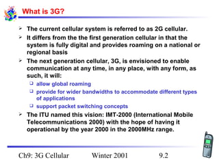
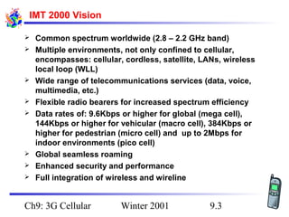
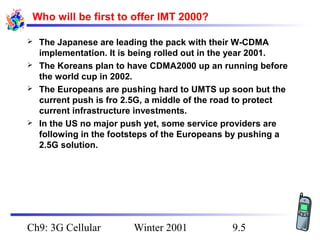
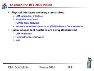
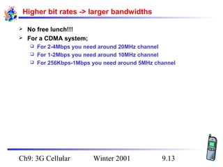
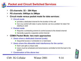
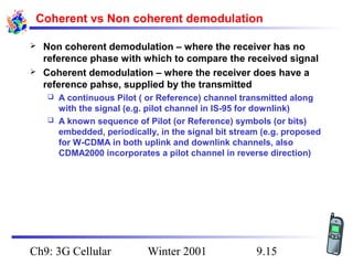
KEMBAR78
Imt 2000 | PPT
Wireless &Mobile Communications
Chapter 9: 3G Cellular
What is 3G?
The ITU’s International Vision
 The need/motivation for 3G
The Major Players
 3G Architecture and Services
 W-CDMA and CDMA2000 technologies

What is 3G?





The current cellular system is referred to as 2G cellular.
It differs from the the first generation cellular in that the
system is fully digital and provides roaming on a national or
regional basis
The next generation cellular, 3G, is envisioned to enable
communication at any time, in any place, with any form, as
such, it will:
allow global roaming
 provide for wider bandwidths to accommodate different types
of applications
 support packet switching concepts




The ITU named this vision: IMT-2000 (International Mobile
Telecommunications 2000) with the hope of having it
operational by the year 2000 in the 2000MHz range.

Ch9: 3G Cellular

Winter 2001

9.2
IMT 2000 Vision











Common spectrum worldwide (2.8 – 2.2 GHz band)
Multiple environments, not only confined to cellular,
encompasses: cellular, cordless, satellite, LANs, wireless
local loop (WLL)
Wide range of telecommunications services (data, voice,
multimedia, etc.)
Flexible radio bearers for increased spectrum efficiency
Data rates of: 9.6Kbps or higher for global (mega cell),
144Kbps or higher for vehicular (macro cell), 384Kbps or
higher for pedestrian (micro cell) and up to 2Mbps for
indoor environments (pico cell)
Global seamless roaming
Enhanced security and performance
Full integration of wireless and wireline

Ch9: 3G Cellular

Winter 2001

9.3
Major 3G Technologies Proposed for IMT 2000




W-CDMA backward compatible with GSM (called UMTS by
the ETSI)
The IS-95 standard (CDMAOne) is evolving its own vision of
3G: CDMA2000
The IS-136 standard is evolving its own migration to 3G,
Universal Wireless Communications, UWC-136 or IS-136 HS

Ch9: 3G Cellular

Winter 2001

9.4
Who will be first to offer IMT 2000?






The Japanese are leading the pack with their W-CDMA
implementation. It is being rolled out in the year 2001.
The Koreans plan to have CDMA2000 up an running before
the world cup in 2002.
The Europeans are pushing hard to UMTS up soon but the
current push is fro 2.5G, a middle of the road to protect
current infrastructure investments.
In the US no major push yet, some service providers are
following in the footsteps of the Europeans by pushing a
2.5G solution.

Ch9: 3G Cellular

Winter 2001

9.5
IMT 2000 Services/Capabilities 1/2


All what 2G support including:
Registration, authentication and encryption
 SMS
 Emergency calling




Bit rates:
144Kbps or higher for vehicular (macro cell),
 384Kbps or higher for pedestrian (micro cell) and
 up to 2Mbps for indoor environments (pico cell)




Billing/charging/user profiles
Sharing of usage/rate information between service providers
 Standardized call detail recording
 Standardized user profiles


Ch9: 3G Cellular

Winter 2001

9.6
IMT 2000 Services/Capabilities 2/2


Support of geographic position finding services
For the mobile
 For the network




Support of multimedia services
QoS
 Assymmetric links
 Fixed and variable rate
 Bit rates of up to 2Mpbs





Support of packet services
Internet Access (wireless cellular IP)

Ch9: 3G Cellular

Winter 2001

9.7
IMT 2000 Family Concept




The IMT 2000 family concept defines some basic
interoperability capabilities between different IMT 2000
technologies to enable global roaming!
Different Radio Access Networks (RANs):
CDMA2000
 W-CDMA
 UWC-136




Different Core Network standards
IS 41
 GSM
 ISDN


Ch9: 3G Cellular

Winter 2001

9.8
Challenge for the Family Concept


With IMT 2000 Standard Interfaces and Capabilities:








Any Family RAN could interface with any Family Core Network
for some minimum set of features.

More advanced features are possible in limited regions
where the Family RAN and the Family Core Network are
optimally matched
The Core Network functionality should be kept independent
of the Radio technology.
By maintaining independence, each can evolve separately
based on needs
User Identity Modules (UIM) Plug-In modules could be used
in locally rented handsets for Global Roaming with at least
the minimum feature set. (similar to GSM SIMs)

Ch9: 3G Cellular

Winter 2001

9.9
UIM Roaming


UIM cards should allow a subscriber to obtain:
Any IMT 2000 service/capability basic feature set on
 Any IMT 2000 Network family member (W-CDMA, CDMA2000
and UWC-136)




UIM Card: will be a superset of the current GSM SIM
Contains all necessary information about the user’s service
subscriptions
 Supports user identity separate from handset identity:


Allows a user to use different handsets, with all usage billed to the
single user
Allows a user to rent a handset in a foreign country/network and obtain
instant service

Ch9: 3G Cellular

Winter 2001

9.10
To reach the IMT 2000 vision


Physical interfaces are being standardized:
UIM to handset interface
 Radio/Air interfaces
 RAN to Core Network
 Network to Network Interfaces (NNI) between Core Networks




Radio independent functions are being standardized:
UIM to handset
 Handset to Core Network
 NNI


Ch9: 3G Cellular

Winter 2001

9.11
Key Technology Concepts for 3G



Higher bit rates required -> more bandwidth
Packet and circuit switched services
Coherent demodulation
TDD
Architecting for minimum required Eb/Io



Control Eb



Limit/Cancel Io



Smart antennas






Ch9: 3G Cellular

Winter 2001

9.12
Higher bit rates -> larger bandwidths



No free lunch!!!
For a CDMA system;
For 2-4Mbps you need around 20MHz channel
 For 1-2Mbps you need around 10MHz channel
 For 256Kbps-1Mbps you need around 5MHz channel


Ch9: 3G Cellular

Winter 2001

9.13
Packet and Circuit Switched Services
CS channels: 32 – 384 Kbps
 PS channels: 64Kbps to 2Mbps
 Circuit mode versus packet mode for data services:




Circuit mode
provides a dedicated channel for the duration of the call
Can mux control with data in same channel, can be a problem for data if bit
stealing is used



Packet mode
Requires a scheduling scheme to control access to the shared channel
Generally supports a separate control channel



CDMA Packet Mode: two main approaches


Users share a dedicated channel (code):
Sequential access or scheduled on a need basis



Users share the allowable total interference for the carrier:
Each user gets a unique code
Users must be scheduled and transmissions controlled to limit the load in the
system



Combination of the above two

Ch9: 3G Cellular

Winter 2001

9.14
Coherent vs Non coherent demodulation



Non coherent demodulation – where the receiver has no
reference phase with which to compare the received signal
Coherent demodulation – where the receiver does have a
reference pahse, supplied by the transmitted
A continuous Pilot ( or Reference) channel transmitted along
with the signal (e.g. pilot channel in IS-95 for downlink)
 A known sequence of Pilot (or Reference) symbols (or bits)
embedded, periodically, in the signal bit stream (e.g. proposed
for W-CDMA in both uplink and downlink channels, also
CDMA2000 incorporates a pilot channel in reverse direction)


Ch9: 3G Cellular

Winter 2001

9.15
TDD


All the standards naturally support FDD




TDD can be added to allow transmission and reception in
single frequency band.






Symmetric channels for up and down links

Japanese W-CMDA supports an asymmetric TDD channel in
addition to the FDD support

TDD allows for flexible spectrum usage, does not require
paired frequency bands
Simpler, lower cost handsets – no need for duplex filters
More complex synchronization, the channel flips back and
forth between uplink and downlink.

Ch9: 3G Cellular

Winter 2001

9.16
Architecting for Minimum Required Eb/Io


Eb/Io vs Eb/No vs C/SIR or SNR:
The former two refer to the energy per bit and are therefore
more applicable to digital systems. The latter two are generally
used to refer to analog systems.
 Using I vs N basically has to do with what the noise source is,
in cellular systems it is primarily due to interference so ``I” is
the preferred term.




Eb =P/R
P is the power per bit in units of energy/sec
 R is the signal bit rate in bits/sec







Eb is the received energy per bit of the signal, Io is the
interference power density
Eb is directionally proportional to the received power of the
signal
For CDMA: Eb/Io = (Pm/Itot) x (W/R) = SIR x Processing Gain
Eb/Io is the key parameter in determining the probability of
receiving a bit correctly (I.e., the BER)

Ch9: 3G Cellular

Winter 2001

9.17
Techniques to keep Eb/Io low with higher bit rates



Maximize Frequency diversity – wider bands -> higher
processing gains
Maximize Time diversity –
Rake receivers -> multiple signals with different delays at
receiver,
 interleaving with FEC




Maximize Space diversity –
diverse receive antennas at base station,
 rake receivers -> different signal paths





Use FEC (forward error correction)
All of the above techniques come at a cost:
Higher bandwidth
 More complex receivers (rake, multiple antennas)
 More overhead bits (FEC) per signal


Ch9: 3G Cellular

Winter 2001

9.18
Controlling Eb


More power is required for the transmission of bits at
higher bit rates over the same distance




Limit the distance over which high bit rates maybe sent

Using better antennas that will focus the beam so that:
The transmitter aims at the target without wasting energy in all
directions
 The receiver captures more of the signal as it is focused on a
narrow beam




Fast power control to counteract changes in interference
due to
Changing loads
 Changing environments


Ch9: 3G Cellular

Winter 2001

9.19
Limit Io





Use better antennas with focused beams in conjunction
with sectors
Use interference cancellation -> receive all signals and
subtract all but the desired one from the total
Use more accurate and fasted power control techniques
To not transmit signals when there is a silence in the signal

Ch9: 3G Cellular

Winter 2001

9.20
Smart Antennas


Switched beams:
Several antenna beams used to receive the signal
 Use the antenna that receives the strongest signal
 Not well suited to CDMA:


Switching will cause chip errors
Switching could disturb synchronization and demodulation
Works against the concept of the Rake receiver


Adaptive Arrays:
Narrow beam antenna which is steered to follow the mobile(s)
 Better suited to CDMA but still have the Rake receiver problem


Ch9: 3G Cellular

Winter 2001

9.21

Imt 2000

  • 1.
    Wireless &Mobile Communications Chapter9: 3G Cellular What is 3G? The ITU’s International Vision  The need/motivation for 3G The Major Players  3G Architecture and Services  W-CDMA and CDMA2000 technologies 
  • 2.
    What is 3G?    Thecurrent cellular system is referred to as 2G cellular. It differs from the the first generation cellular in that the system is fully digital and provides roaming on a national or regional basis The next generation cellular, 3G, is envisioned to enable communication at any time, in any place, with any form, as such, it will: allow global roaming  provide for wider bandwidths to accommodate different types of applications  support packet switching concepts   The ITU named this vision: IMT-2000 (International Mobile Telecommunications 2000) with the hope of having it operational by the year 2000 in the 2000MHz range. Ch9: 3G Cellular Winter 2001 9.2
  • 3.
    IMT 2000 Vision         Commonspectrum worldwide (2.8 – 2.2 GHz band) Multiple environments, not only confined to cellular, encompasses: cellular, cordless, satellite, LANs, wireless local loop (WLL) Wide range of telecommunications services (data, voice, multimedia, etc.) Flexible radio bearers for increased spectrum efficiency Data rates of: 9.6Kbps or higher for global (mega cell), 144Kbps or higher for vehicular (macro cell), 384Kbps or higher for pedestrian (micro cell) and up to 2Mbps for indoor environments (pico cell) Global seamless roaming Enhanced security and performance Full integration of wireless and wireline Ch9: 3G Cellular Winter 2001 9.3
  • 4.
    Major 3G TechnologiesProposed for IMT 2000    W-CDMA backward compatible with GSM (called UMTS by the ETSI) The IS-95 standard (CDMAOne) is evolving its own vision of 3G: CDMA2000 The IS-136 standard is evolving its own migration to 3G, Universal Wireless Communications, UWC-136 or IS-136 HS Ch9: 3G Cellular Winter 2001 9.4
  • 5.
    Who will befirst to offer IMT 2000?     The Japanese are leading the pack with their W-CDMA implementation. It is being rolled out in the year 2001. The Koreans plan to have CDMA2000 up an running before the world cup in 2002. The Europeans are pushing hard to UMTS up soon but the current push is fro 2.5G, a middle of the road to protect current infrastructure investments. In the US no major push yet, some service providers are following in the footsteps of the Europeans by pushing a 2.5G solution. Ch9: 3G Cellular Winter 2001 9.5
  • 6.
    IMT 2000 Services/Capabilities1/2  All what 2G support including: Registration, authentication and encryption  SMS  Emergency calling   Bit rates: 144Kbps or higher for vehicular (macro cell),  384Kbps or higher for pedestrian (micro cell) and  up to 2Mbps for indoor environments (pico cell)   Billing/charging/user profiles Sharing of usage/rate information between service providers  Standardized call detail recording  Standardized user profiles  Ch9: 3G Cellular Winter 2001 9.6
  • 7.
    IMT 2000 Services/Capabilities2/2  Support of geographic position finding services For the mobile  For the network   Support of multimedia services QoS  Assymmetric links  Fixed and variable rate  Bit rates of up to 2Mpbs    Support of packet services Internet Access (wireless cellular IP) Ch9: 3G Cellular Winter 2001 9.7
  • 8.
    IMT 2000 FamilyConcept   The IMT 2000 family concept defines some basic interoperability capabilities between different IMT 2000 technologies to enable global roaming! Different Radio Access Networks (RANs): CDMA2000  W-CDMA  UWC-136   Different Core Network standards IS 41  GSM  ISDN  Ch9: 3G Cellular Winter 2001 9.8
  • 9.
    Challenge for theFamily Concept  With IMT 2000 Standard Interfaces and Capabilities:      Any Family RAN could interface with any Family Core Network for some minimum set of features. More advanced features are possible in limited regions where the Family RAN and the Family Core Network are optimally matched The Core Network functionality should be kept independent of the Radio technology. By maintaining independence, each can evolve separately based on needs User Identity Modules (UIM) Plug-In modules could be used in locally rented handsets for Global Roaming with at least the minimum feature set. (similar to GSM SIMs) Ch9: 3G Cellular Winter 2001 9.9
  • 10.
    UIM Roaming  UIM cardsshould allow a subscriber to obtain: Any IMT 2000 service/capability basic feature set on  Any IMT 2000 Network family member (W-CDMA, CDMA2000 and UWC-136)   UIM Card: will be a superset of the current GSM SIM Contains all necessary information about the user’s service subscriptions  Supports user identity separate from handset identity:  Allows a user to use different handsets, with all usage billed to the single user Allows a user to rent a handset in a foreign country/network and obtain instant service Ch9: 3G Cellular Winter 2001 9.10
  • 11.
    To reach theIMT 2000 vision  Physical interfaces are being standardized: UIM to handset interface  Radio/Air interfaces  RAN to Core Network  Network to Network Interfaces (NNI) between Core Networks   Radio independent functions are being standardized: UIM to handset  Handset to Core Network  NNI  Ch9: 3G Cellular Winter 2001 9.11
  • 12.
    Key Technology Conceptsfor 3G  Higher bit rates required -> more bandwidth Packet and circuit switched services Coherent demodulation TDD Architecting for minimum required Eb/Io  Control Eb  Limit/Cancel Io  Smart antennas     Ch9: 3G Cellular Winter 2001 9.12
  • 13.
    Higher bit rates-> larger bandwidths   No free lunch!!! For a CDMA system; For 2-4Mbps you need around 20MHz channel  For 1-2Mbps you need around 10MHz channel  For 256Kbps-1Mbps you need around 5MHz channel  Ch9: 3G Cellular Winter 2001 9.13
  • 14.
    Packet and CircuitSwitched Services CS channels: 32 – 384 Kbps  PS channels: 64Kbps to 2Mbps  Circuit mode versus packet mode for data services:   Circuit mode provides a dedicated channel for the duration of the call Can mux control with data in same channel, can be a problem for data if bit stealing is used  Packet mode Requires a scheduling scheme to control access to the shared channel Generally supports a separate control channel  CDMA Packet Mode: two main approaches  Users share a dedicated channel (code): Sequential access or scheduled on a need basis  Users share the allowable total interference for the carrier: Each user gets a unique code Users must be scheduled and transmissions controlled to limit the load in the system  Combination of the above two Ch9: 3G Cellular Winter 2001 9.14
  • 15.
    Coherent vs Noncoherent demodulation   Non coherent demodulation – where the receiver has no reference phase with which to compare the received signal Coherent demodulation – where the receiver does have a reference pahse, supplied by the transmitted A continuous Pilot ( or Reference) channel transmitted along with the signal (e.g. pilot channel in IS-95 for downlink)  A known sequence of Pilot (or Reference) symbols (or bits) embedded, periodically, in the signal bit stream (e.g. proposed for W-CDMA in both uplink and downlink channels, also CDMA2000 incorporates a pilot channel in reverse direction)  Ch9: 3G Cellular Winter 2001 9.15
  • 16.
    TDD  All the standardsnaturally support FDD   TDD can be added to allow transmission and reception in single frequency band.     Symmetric channels for up and down links Japanese W-CMDA supports an asymmetric TDD channel in addition to the FDD support TDD allows for flexible spectrum usage, does not require paired frequency bands Simpler, lower cost handsets – no need for duplex filters More complex synchronization, the channel flips back and forth between uplink and downlink. Ch9: 3G Cellular Winter 2001 9.16
  • 17.
    Architecting for MinimumRequired Eb/Io  Eb/Io vs Eb/No vs C/SIR or SNR: The former two refer to the energy per bit and are therefore more applicable to digital systems. The latter two are generally used to refer to analog systems.  Using I vs N basically has to do with what the noise source is, in cellular systems it is primarily due to interference so ``I” is the preferred term.   Eb =P/R P is the power per bit in units of energy/sec  R is the signal bit rate in bits/sec      Eb is the received energy per bit of the signal, Io is the interference power density Eb is directionally proportional to the received power of the signal For CDMA: Eb/Io = (Pm/Itot) x (W/R) = SIR x Processing Gain Eb/Io is the key parameter in determining the probability of receiving a bit correctly (I.e., the BER) Ch9: 3G Cellular Winter 2001 9.17
  • 18.
    Techniques to keepEb/Io low with higher bit rates   Maximize Frequency diversity – wider bands -> higher processing gains Maximize Time diversity – Rake receivers -> multiple signals with different delays at receiver,  interleaving with FEC   Maximize Space diversity – diverse receive antennas at base station,  rake receivers -> different signal paths    Use FEC (forward error correction) All of the above techniques come at a cost: Higher bandwidth  More complex receivers (rake, multiple antennas)  More overhead bits (FEC) per signal  Ch9: 3G Cellular Winter 2001 9.18
  • 19.
    Controlling Eb  More poweris required for the transmission of bits at higher bit rates over the same distance   Limit the distance over which high bit rates maybe sent Using better antennas that will focus the beam so that: The transmitter aims at the target without wasting energy in all directions  The receiver captures more of the signal as it is focused on a narrow beam   Fast power control to counteract changes in interference due to Changing loads  Changing environments  Ch9: 3G Cellular Winter 2001 9.19
  • 20.
    Limit Io     Use betterantennas with focused beams in conjunction with sectors Use interference cancellation -> receive all signals and subtract all but the desired one from the total Use more accurate and fasted power control techniques To not transmit signals when there is a silence in the signal Ch9: 3G Cellular Winter 2001 9.20
  • 21.
    Smart Antennas  Switched beams: Severalantenna beams used to receive the signal  Use the antenna that receives the strongest signal  Not well suited to CDMA:  Switching will cause chip errors Switching could disturb synchronization and demodulation Works against the concept of the Rake receiver  Adaptive Arrays: Narrow beam antenna which is steered to follow the mobile(s)  Better suited to CDMA but still have the Rake receiver problem  Ch9: 3G Cellular Winter 2001 9.21