Downloaded 269 times


The document discusses input and output devices used with programmable logic controllers (PLCs). It describes how input modules convert signals from devices like sensors into logic levels for the PLC processor, while output modules convert signals from the processor into levels that can drive devices like motors and valves. A variety of sensors are described that provide digital input signals to PLCs, including switches, encoders, temperature sensors, and smart sensors with integrated circuitry. Common output devices controlled by PLCs include relays, DC motors, solenoid valves, and stepper motors. Examples of PLC applications include conveyor belts, liquid level monitoring, lifts, and robot control systems.
Overview of the presentation on Input-Output Devices used with PLC by Arko Saha, outlining course details.
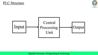
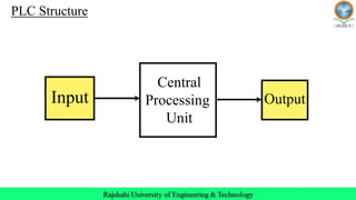
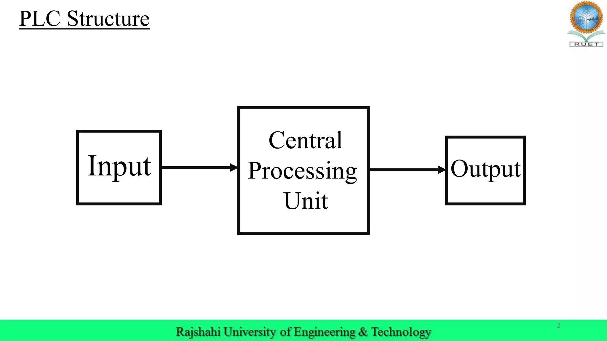
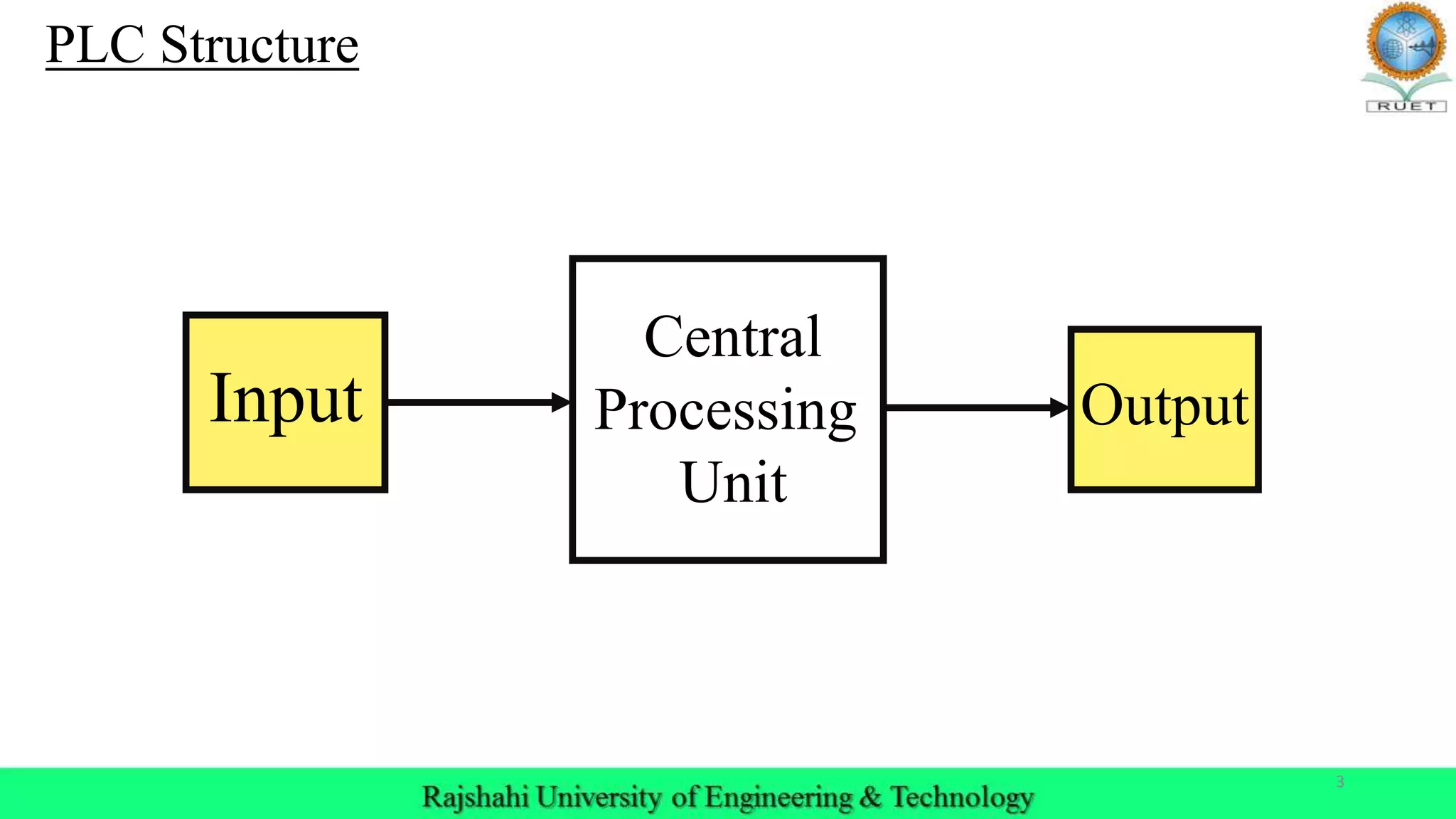
Description of PLC structure consisting of Input, Central Processing Unit, and Output.
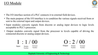
Explains I/O modules in PLC, how they connect external devices, signal conversion details.
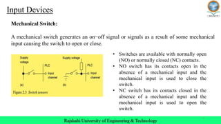
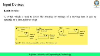
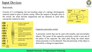
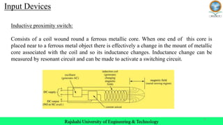
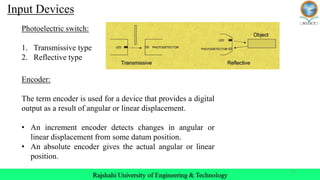
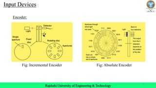
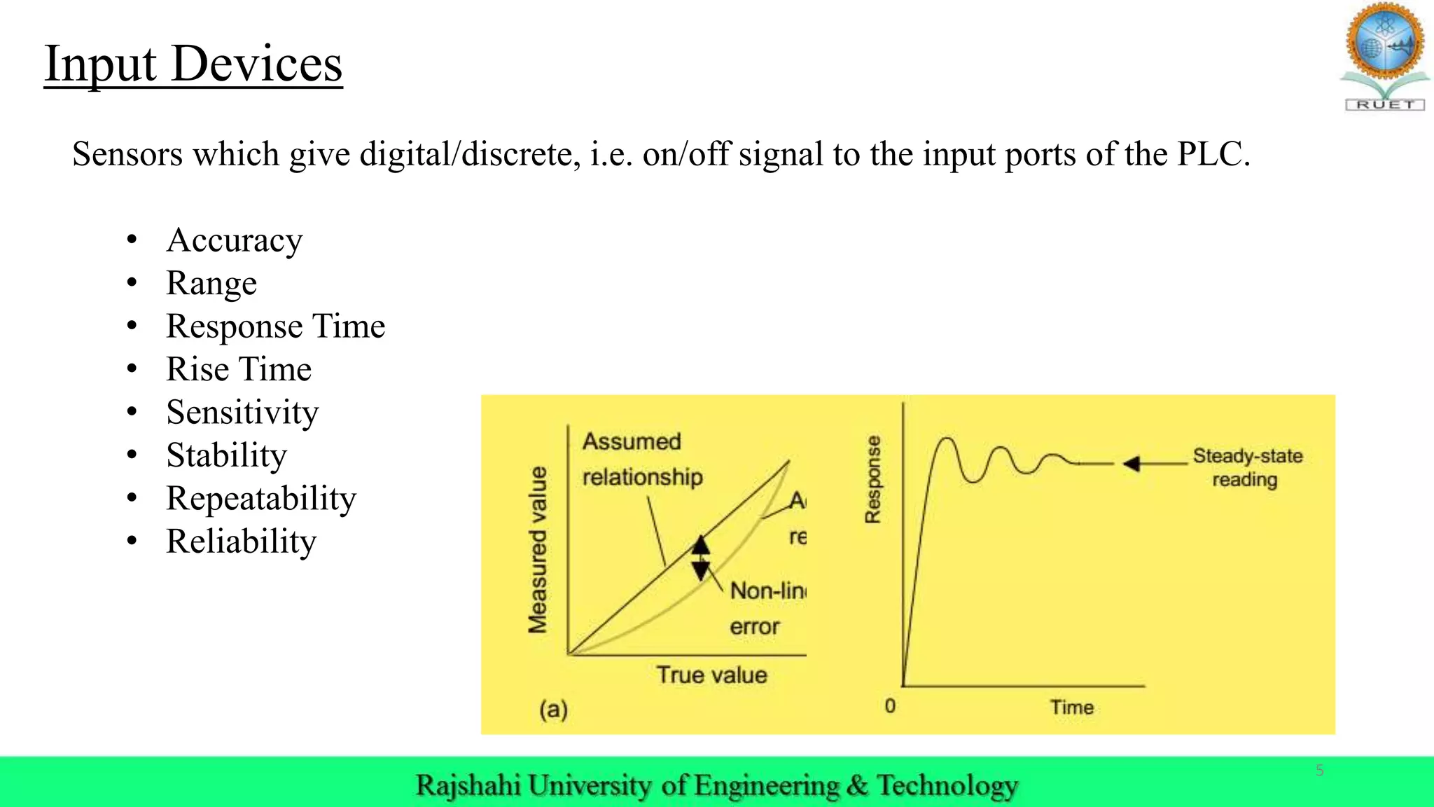
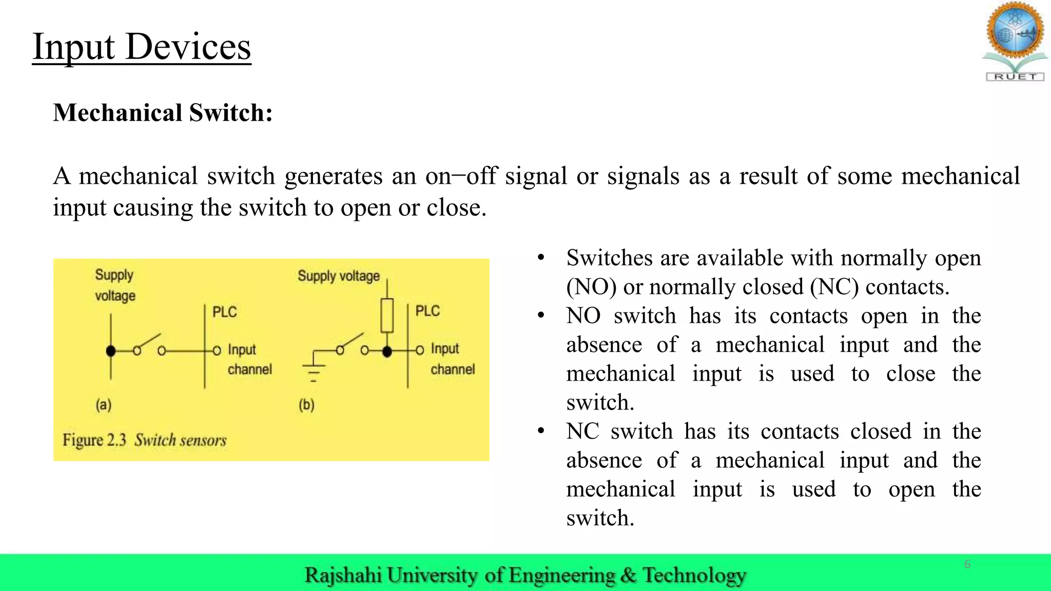
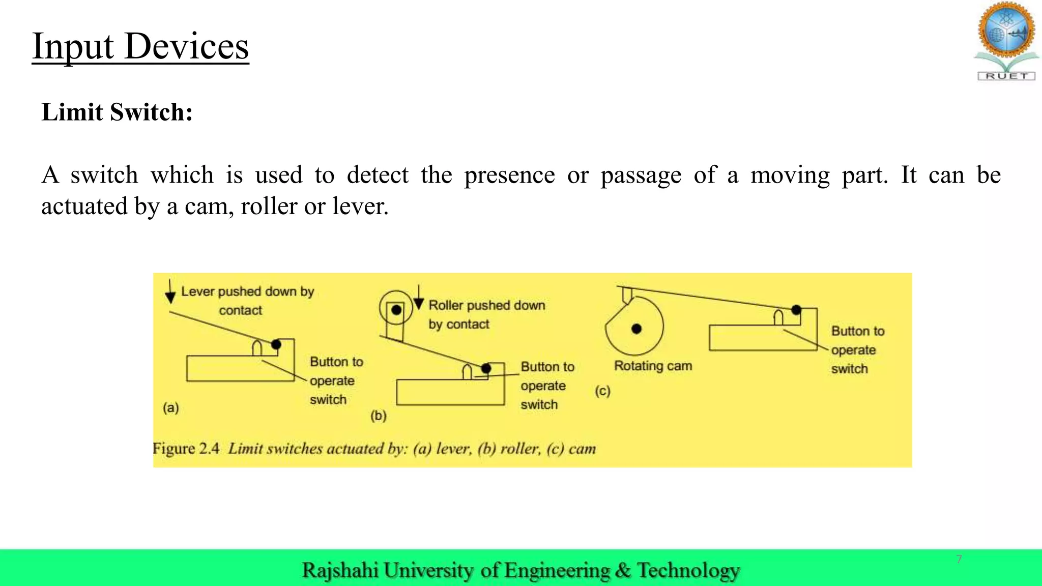
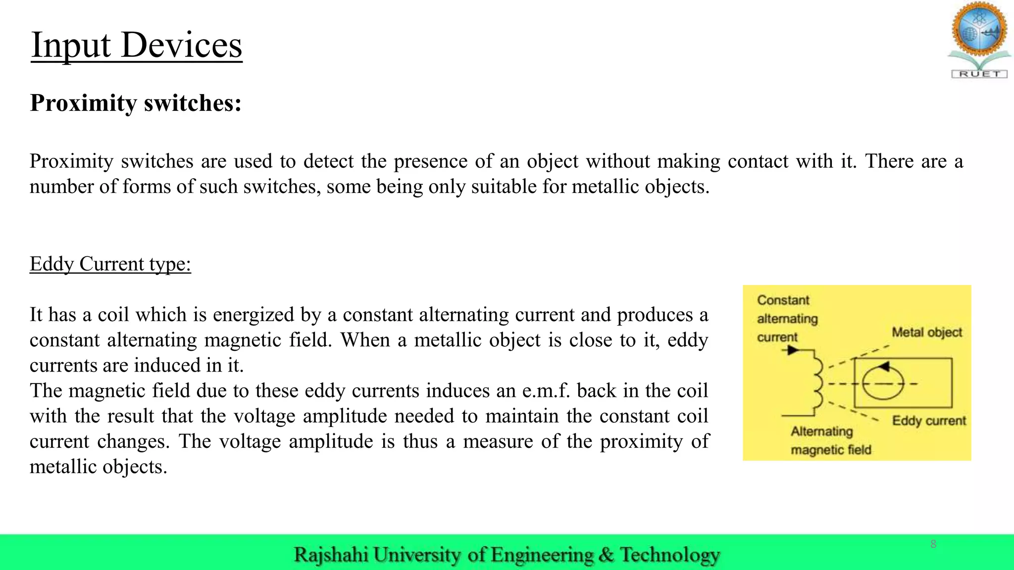
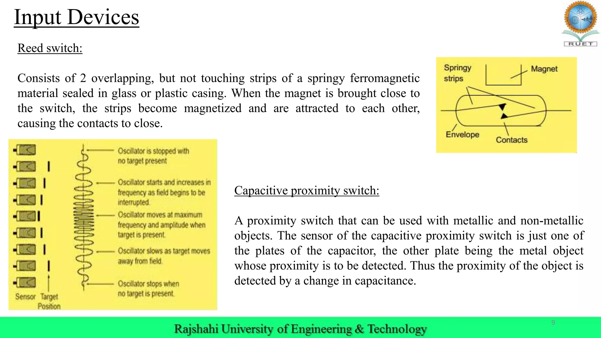
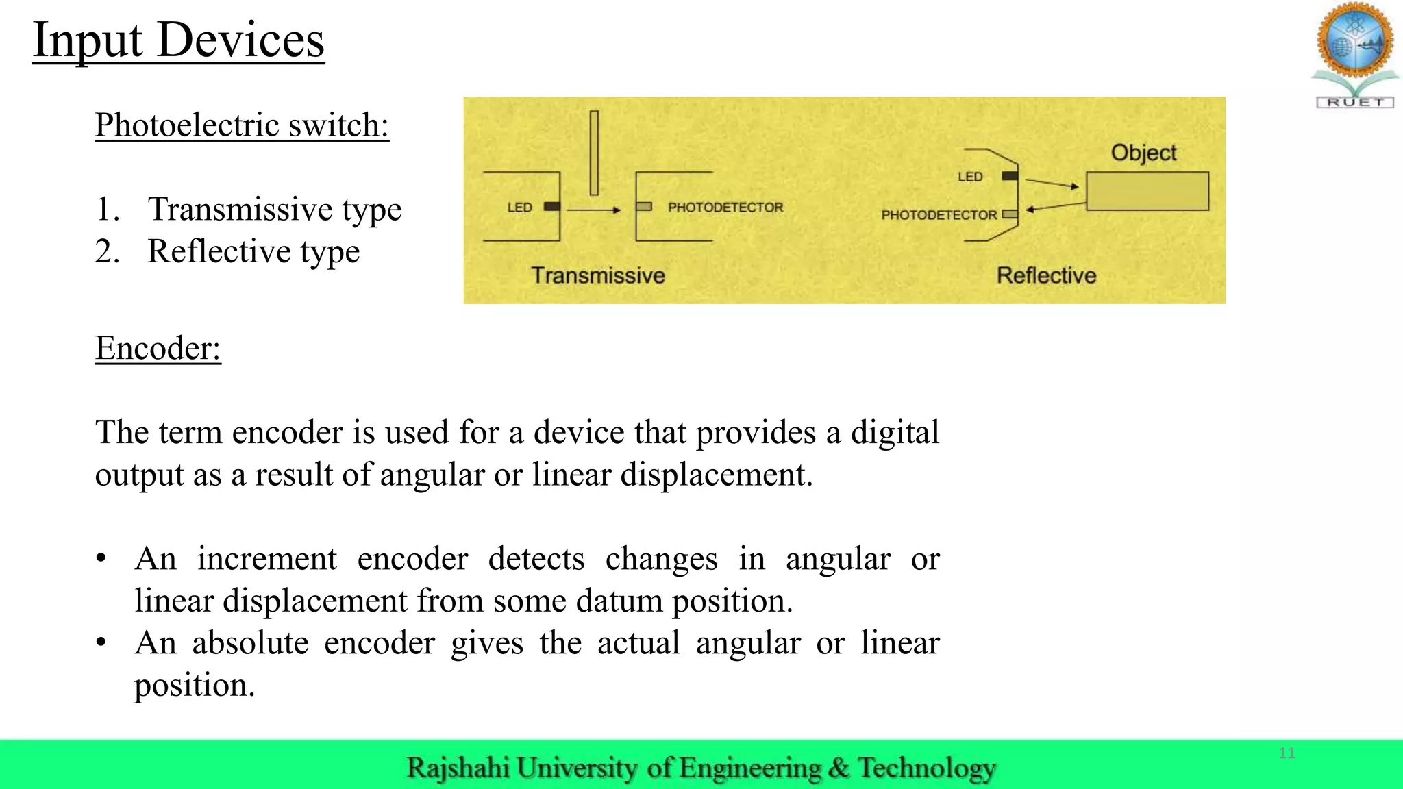
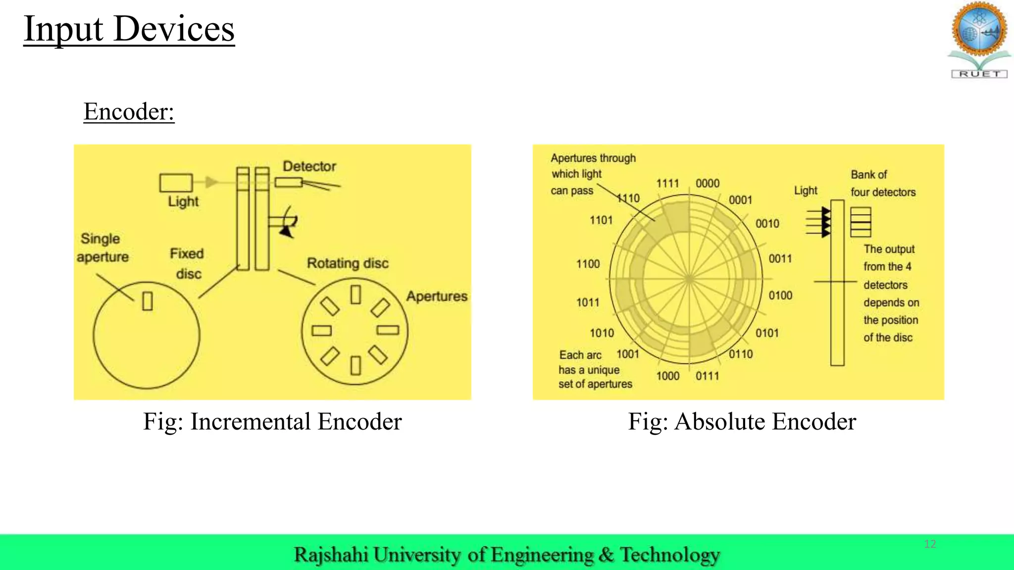
Input devices providing on/off signals include mechanical switches, limit switches, proximity switches, and encoders.
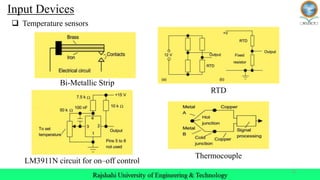
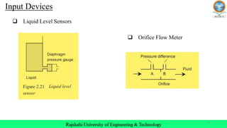
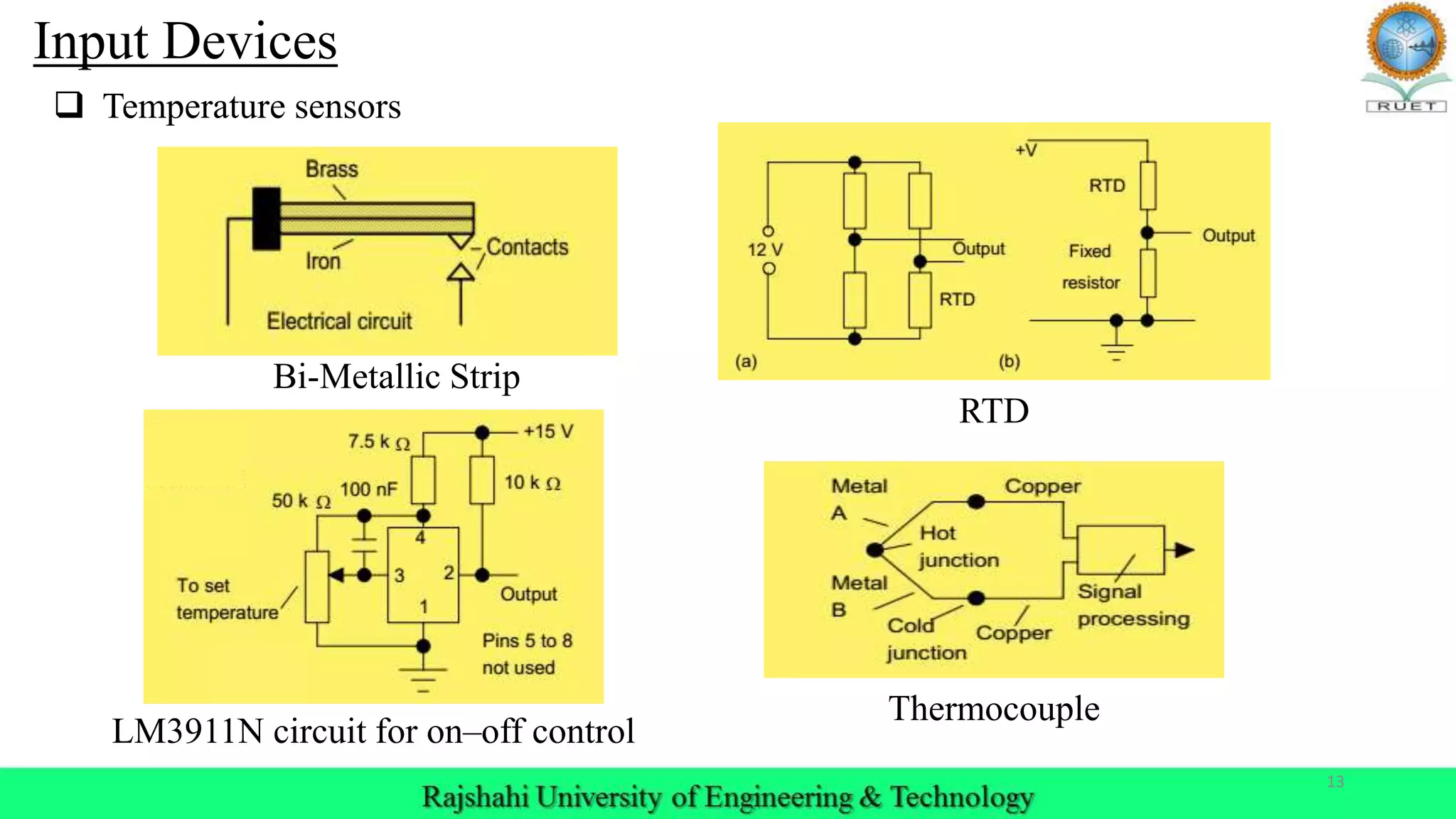
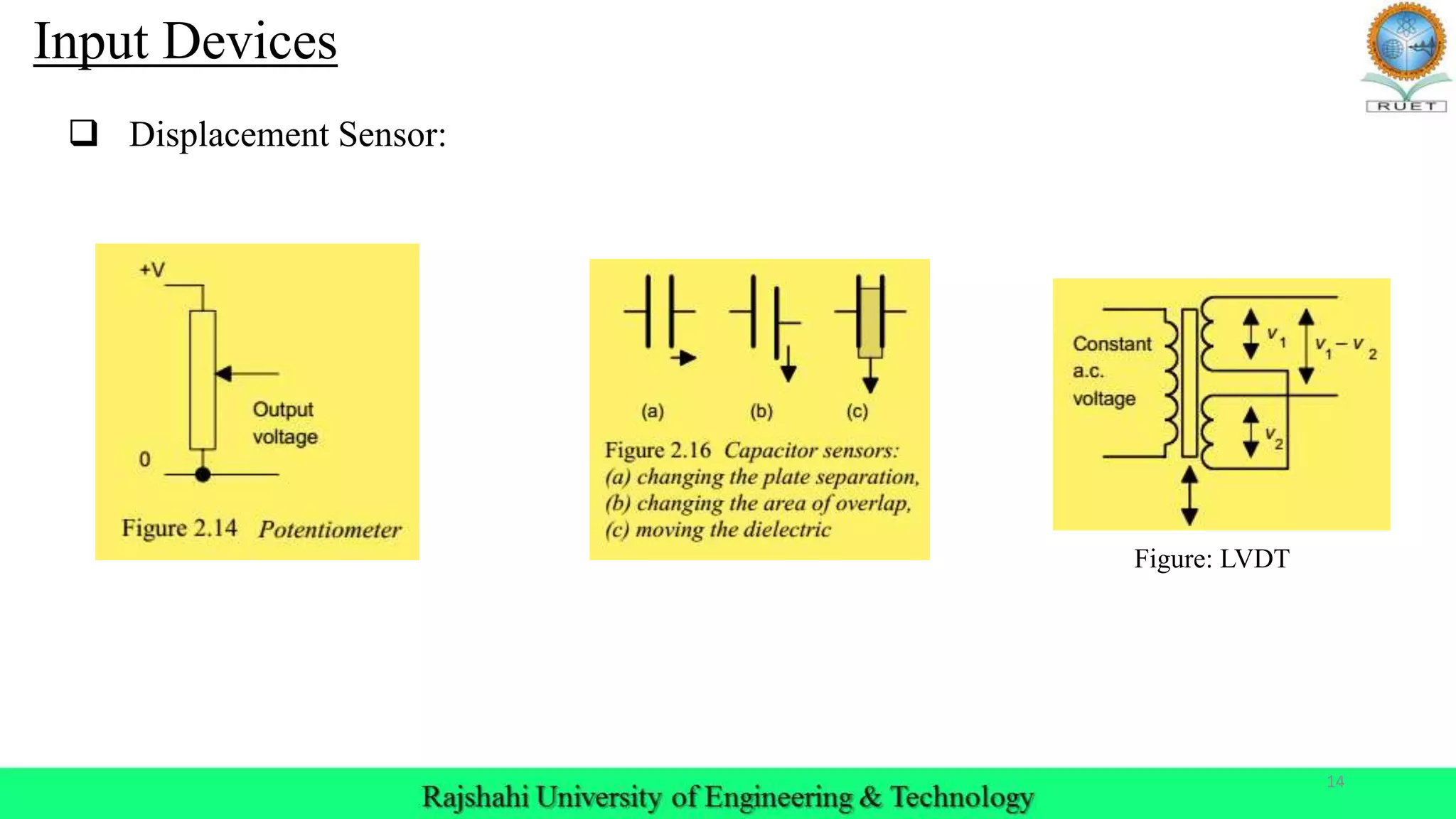
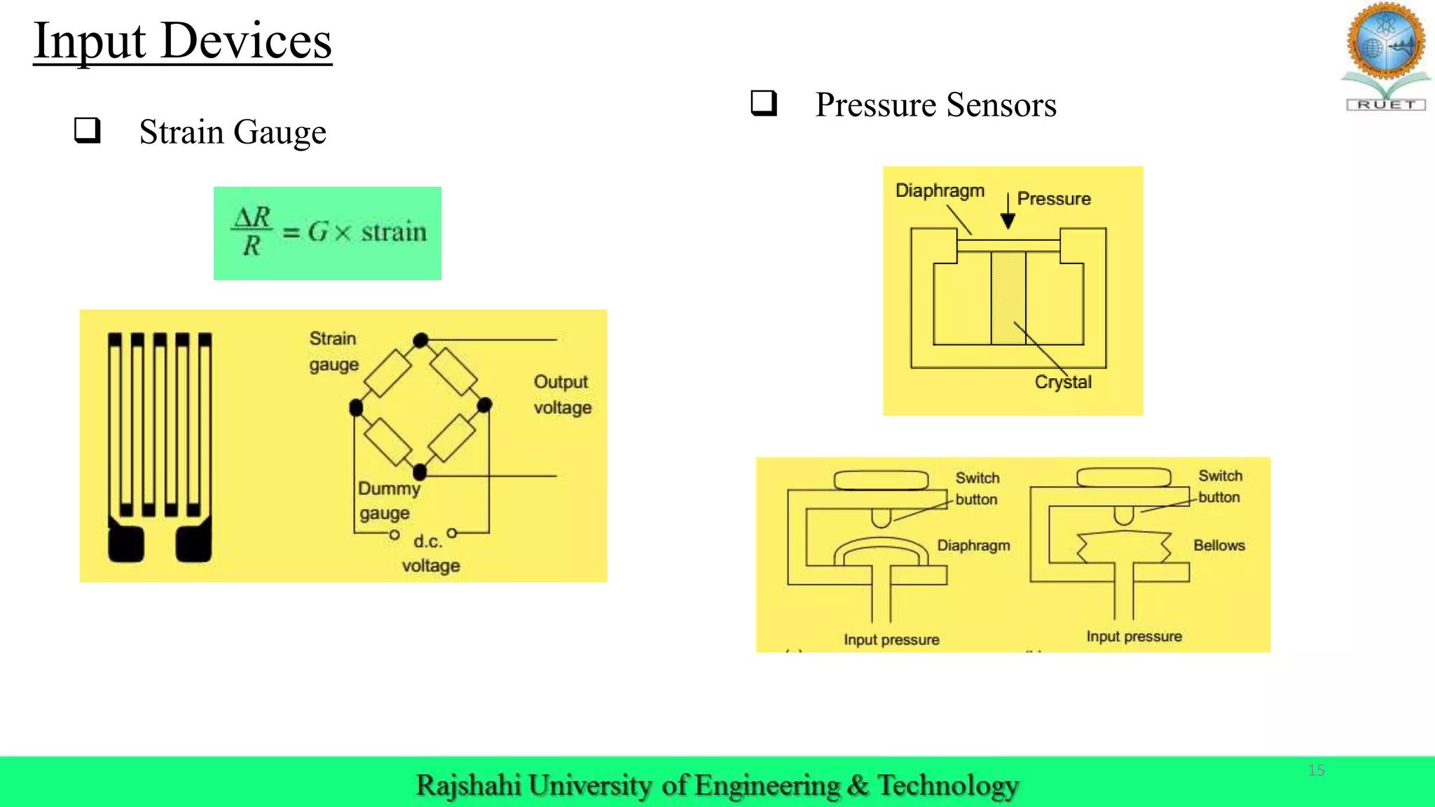
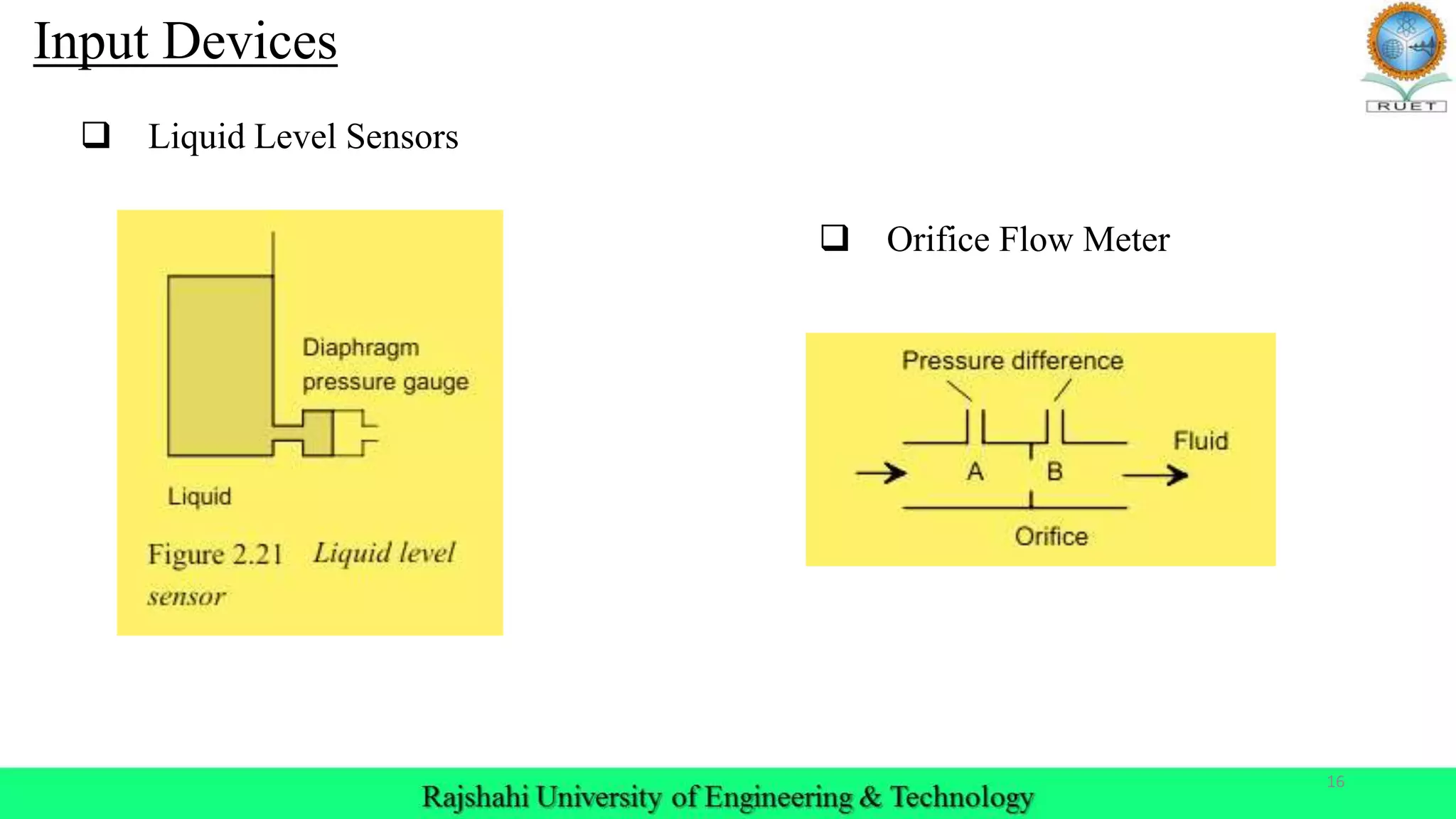
Details on temperature, displacement, strain gauge, pressure, and liquid level sensors used in PLC.
Introduction to smart sensors with integrated circuitry, capabilities, and compliance with IEEE 1451.4 standard.
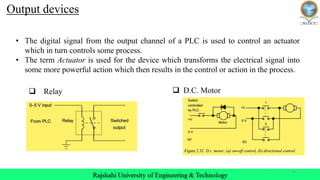
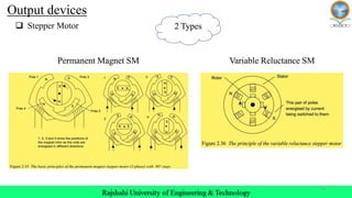
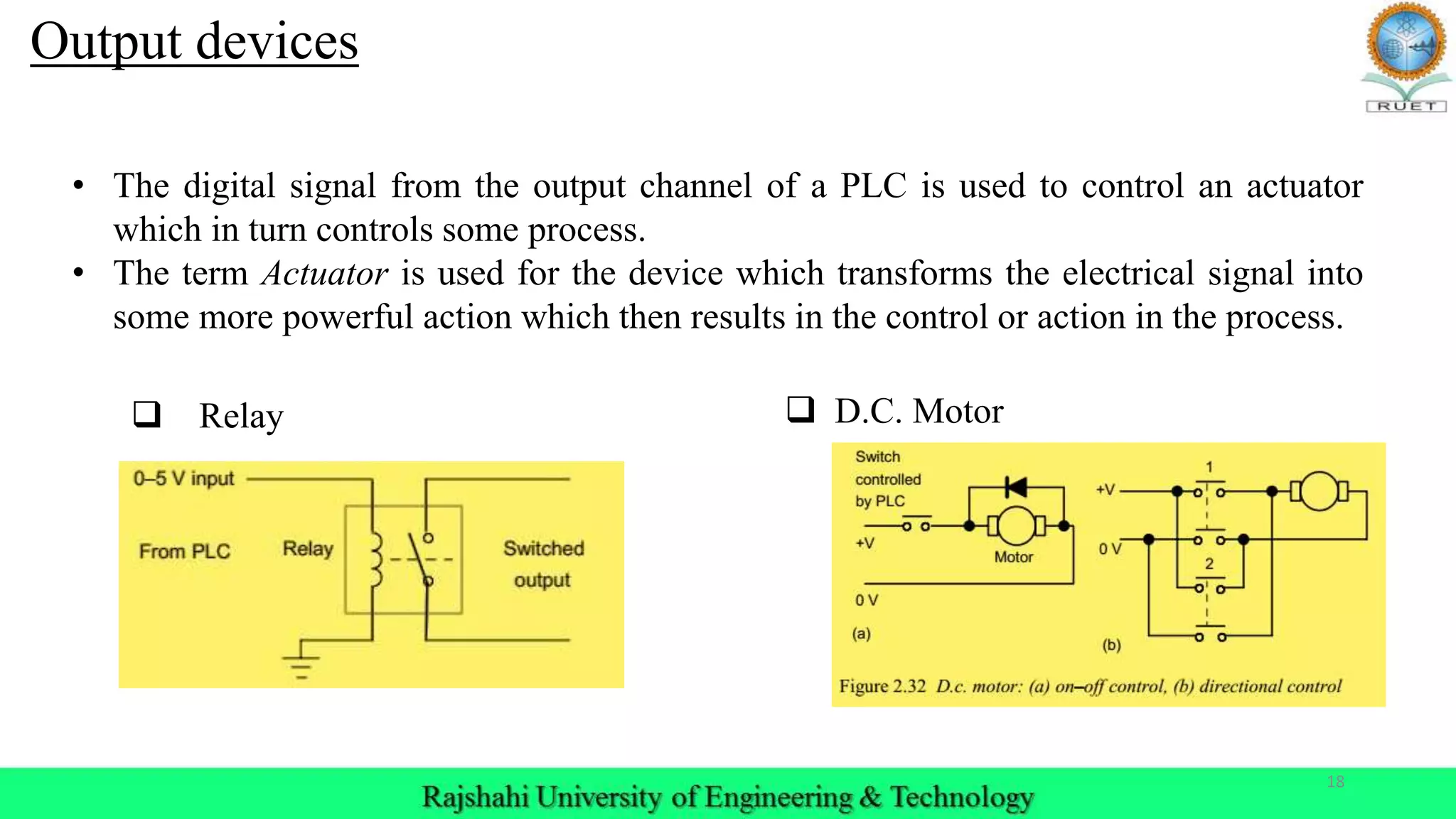
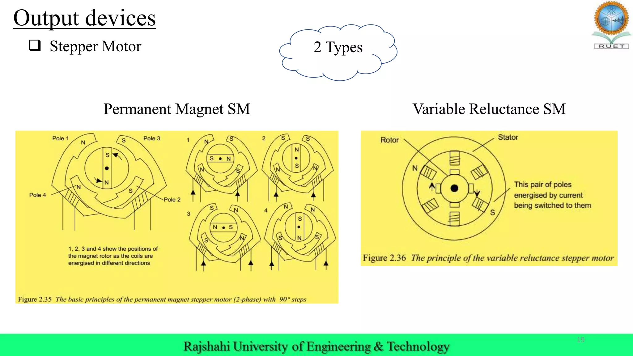
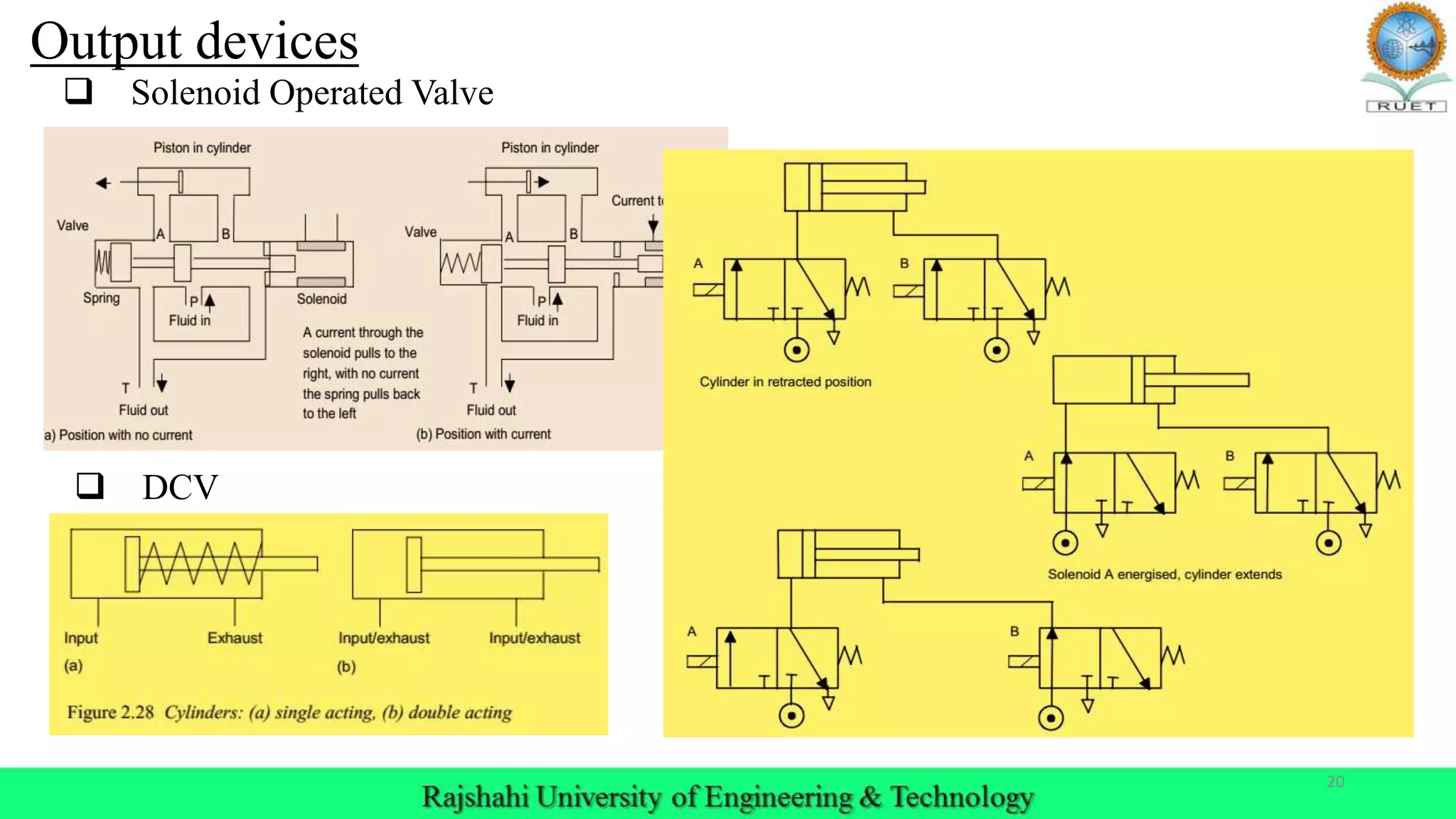
Output devices discussed include relays, DC motors, stepper motors, valve controls, and actuators.
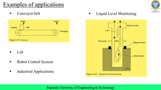
Examples of applications for PLCs such as conveyor belts, liquid level monitoring, lifts, and industrial systems.
Reference material for PLC concepts by W. Bolton and a closing thank you.


![PLC Ladder Programming [Mechatronics]](https://cdn.slidesharecdn.com/ss_thumbnails/plc-ppt-snteli-200503070616-thumbnail.jpg?width=600ounds&width=560&fit=bounds)


