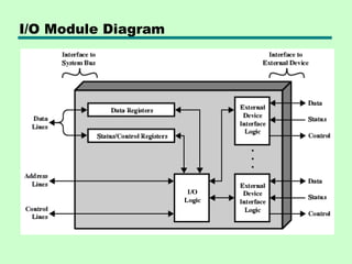
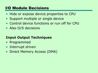
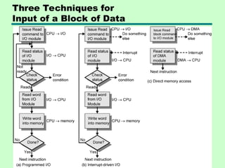
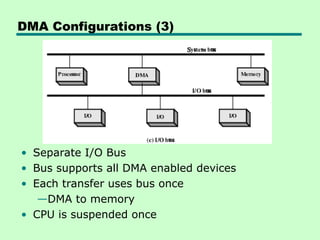
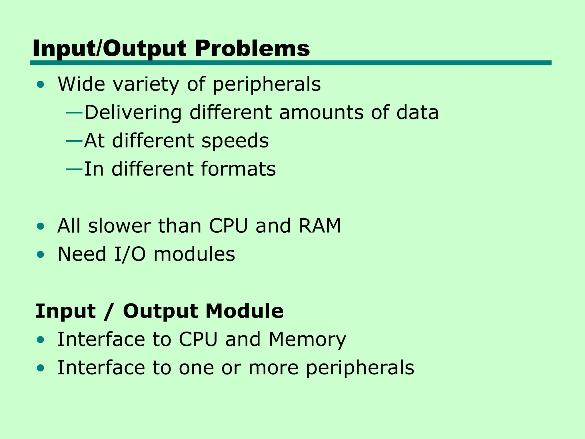
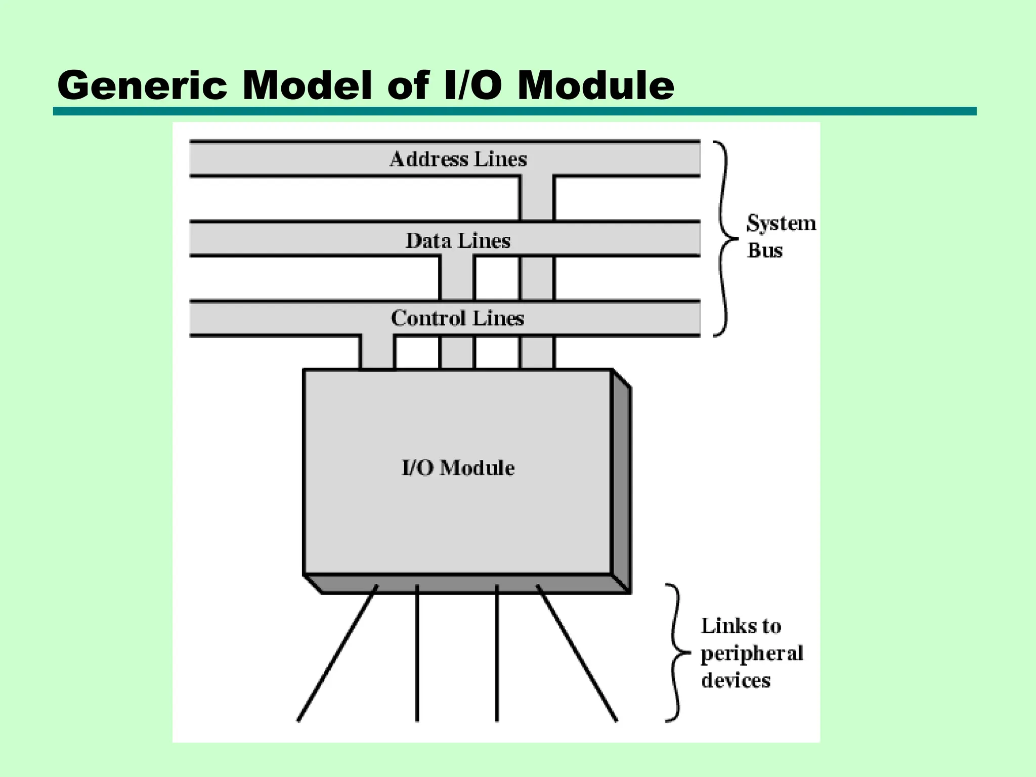
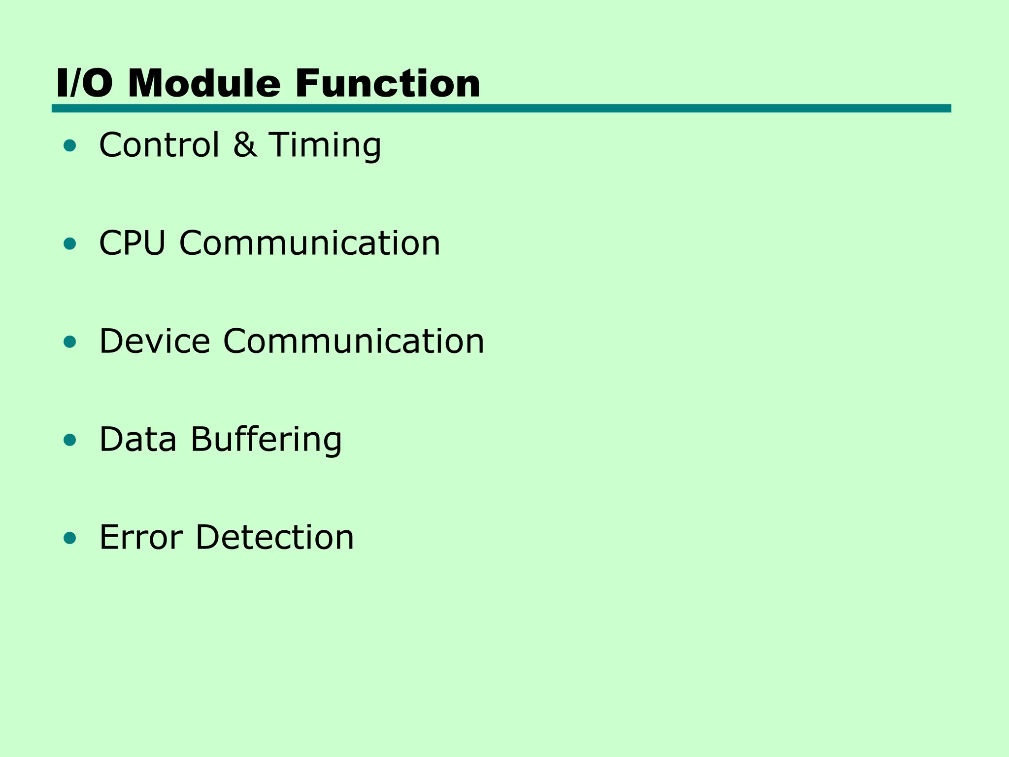
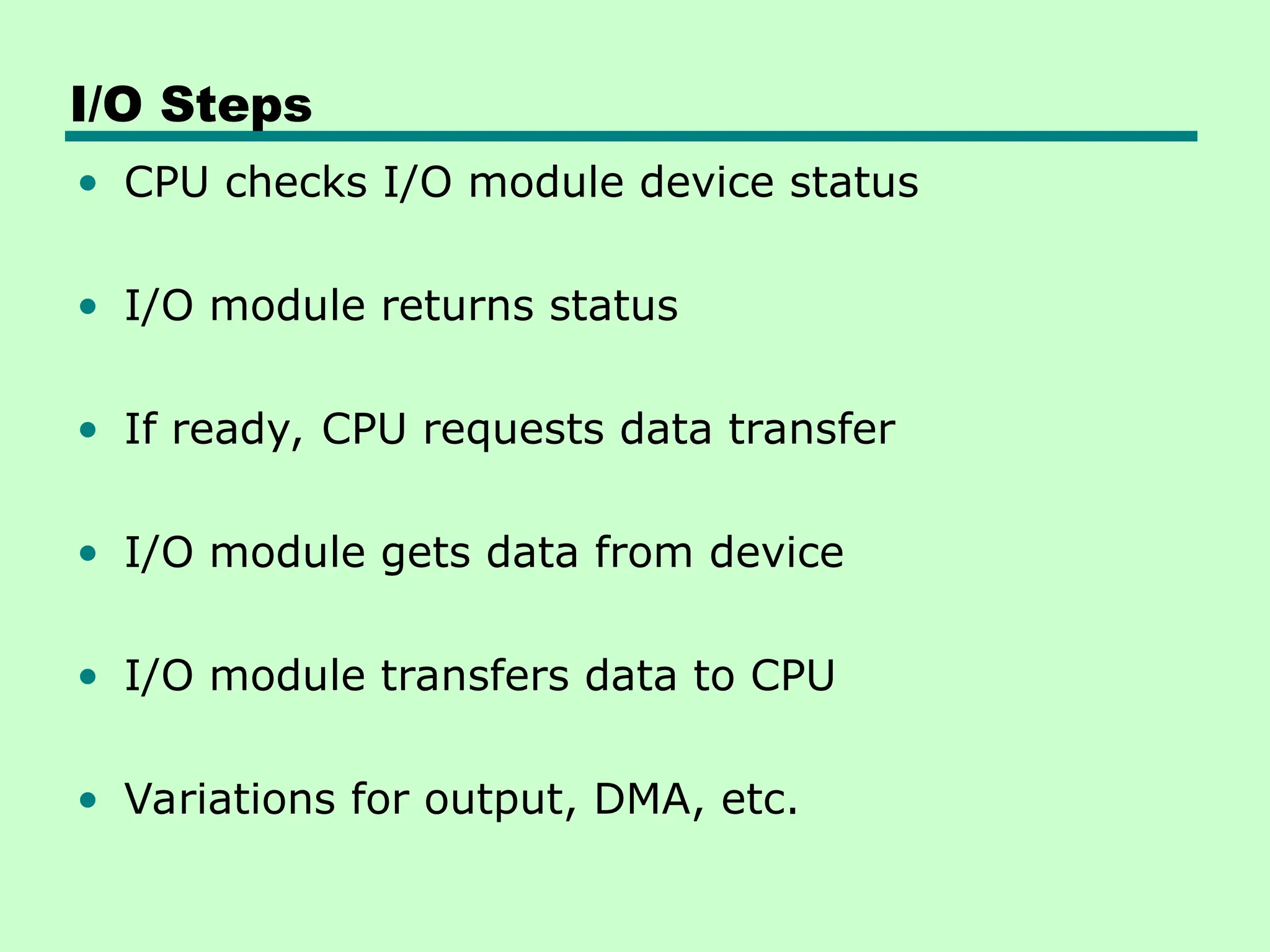
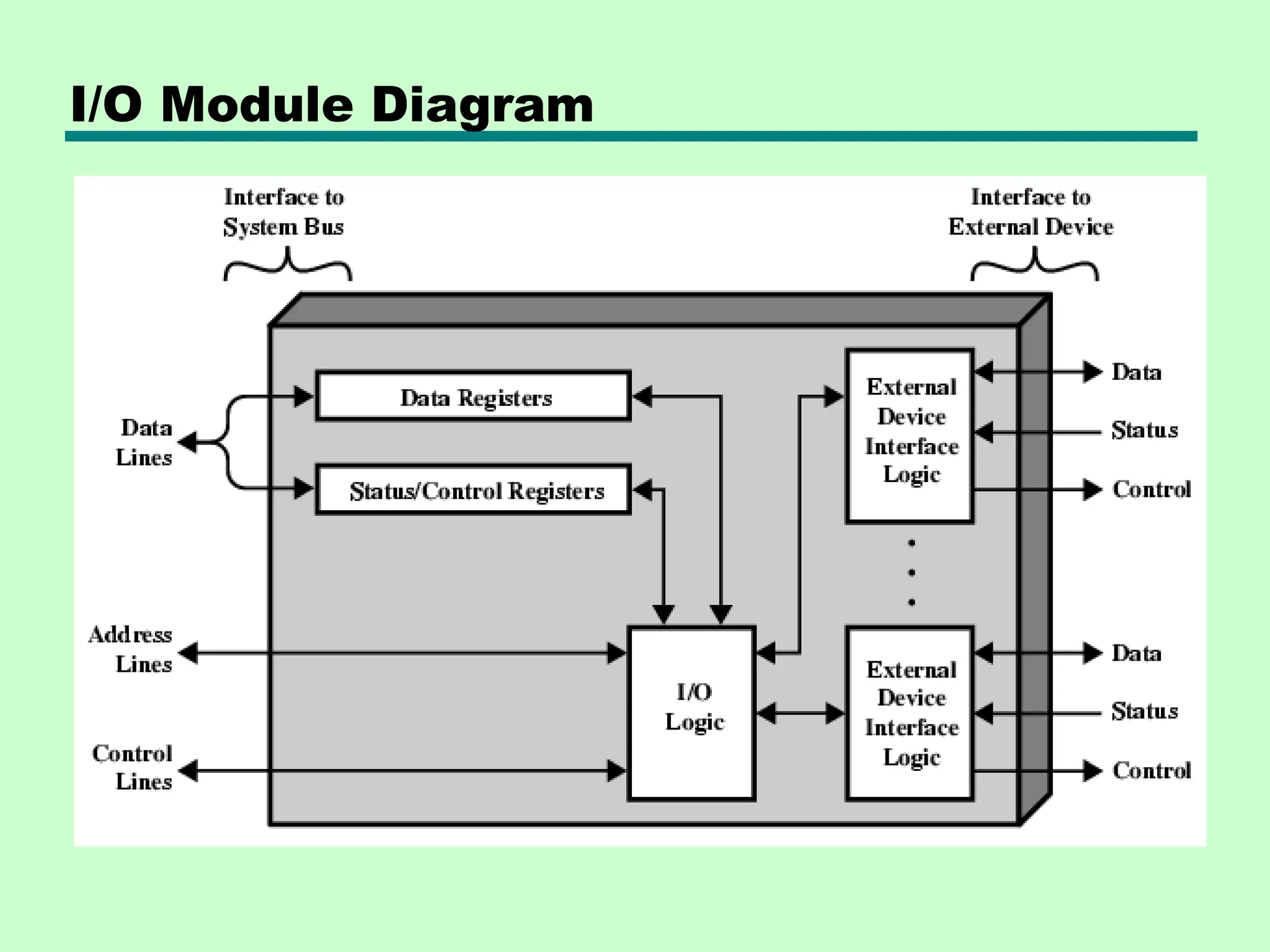
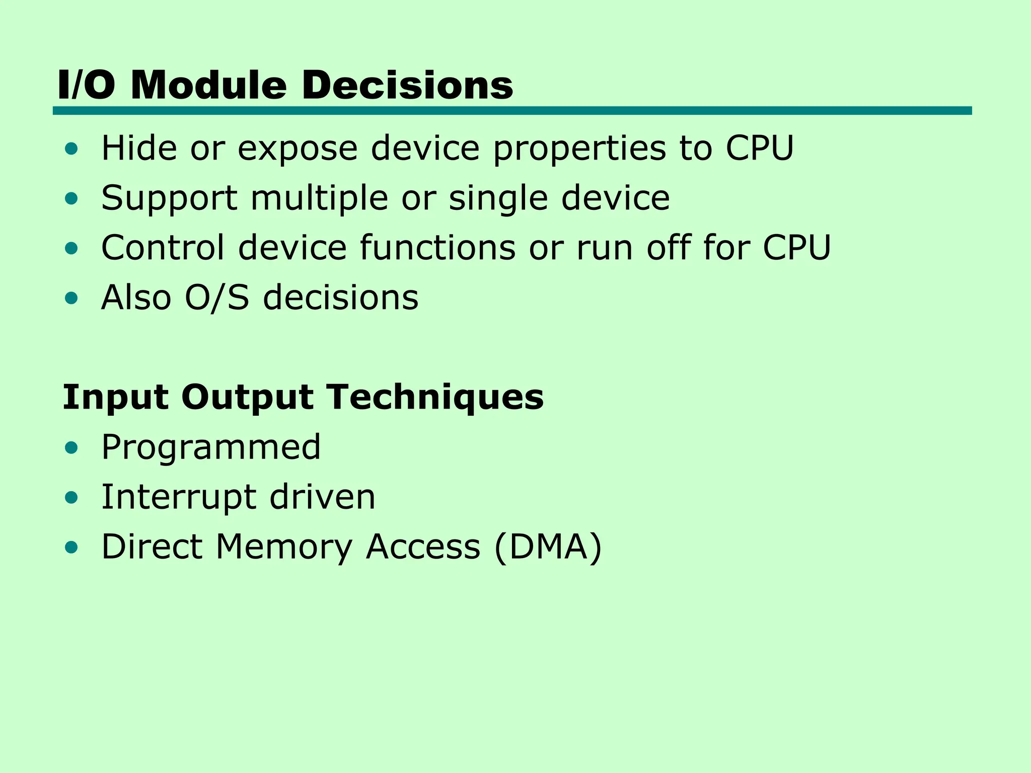
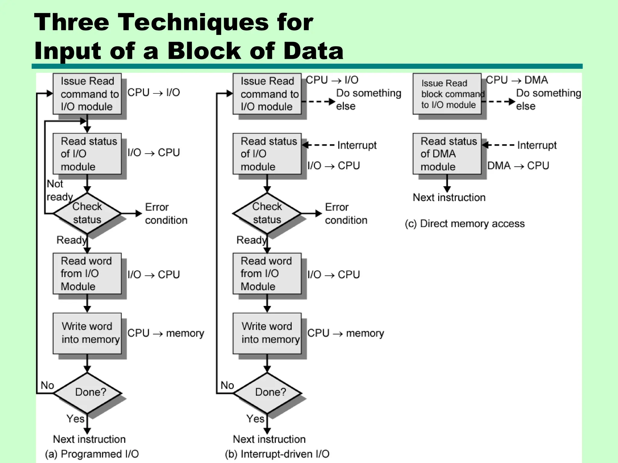
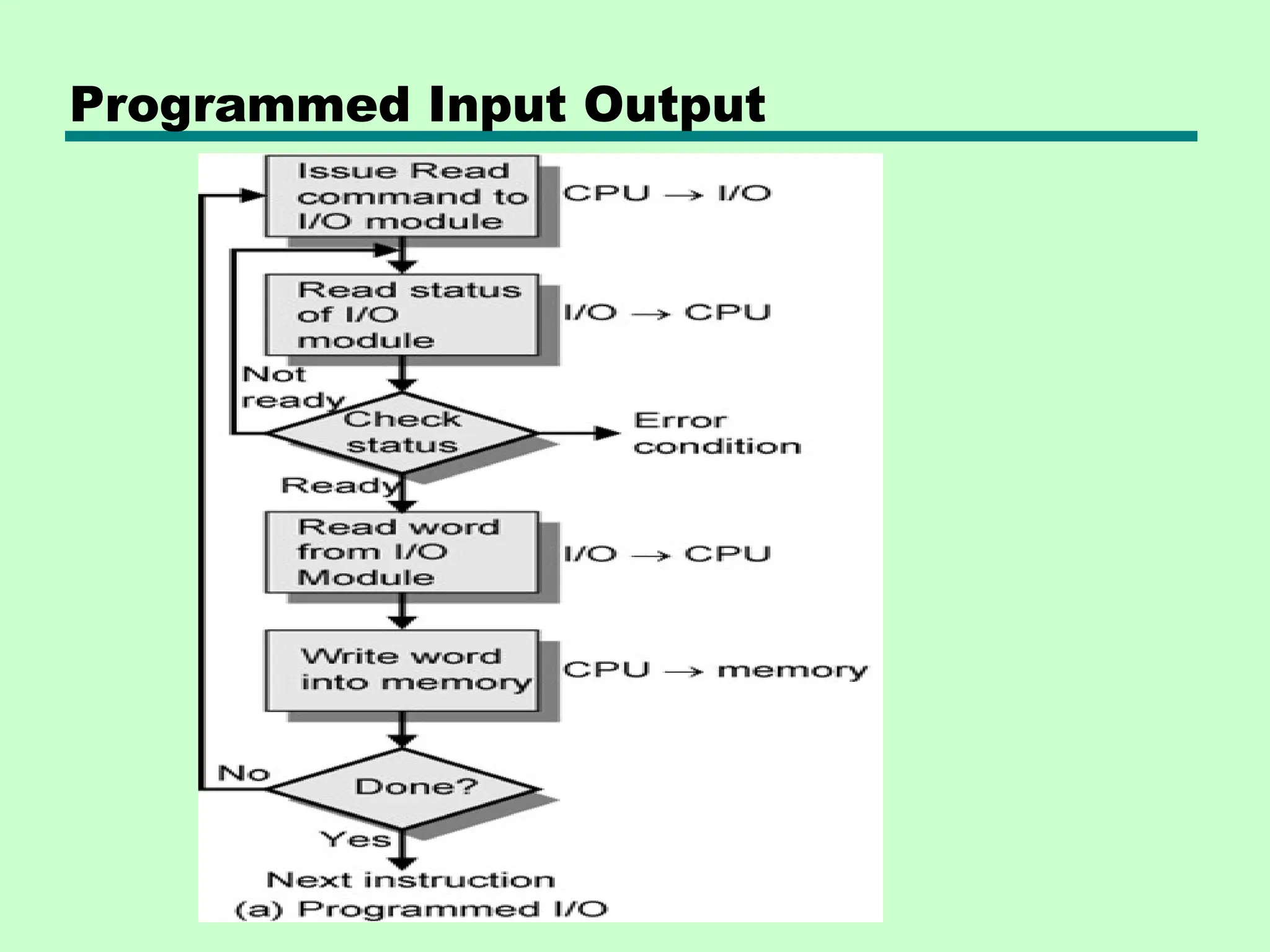
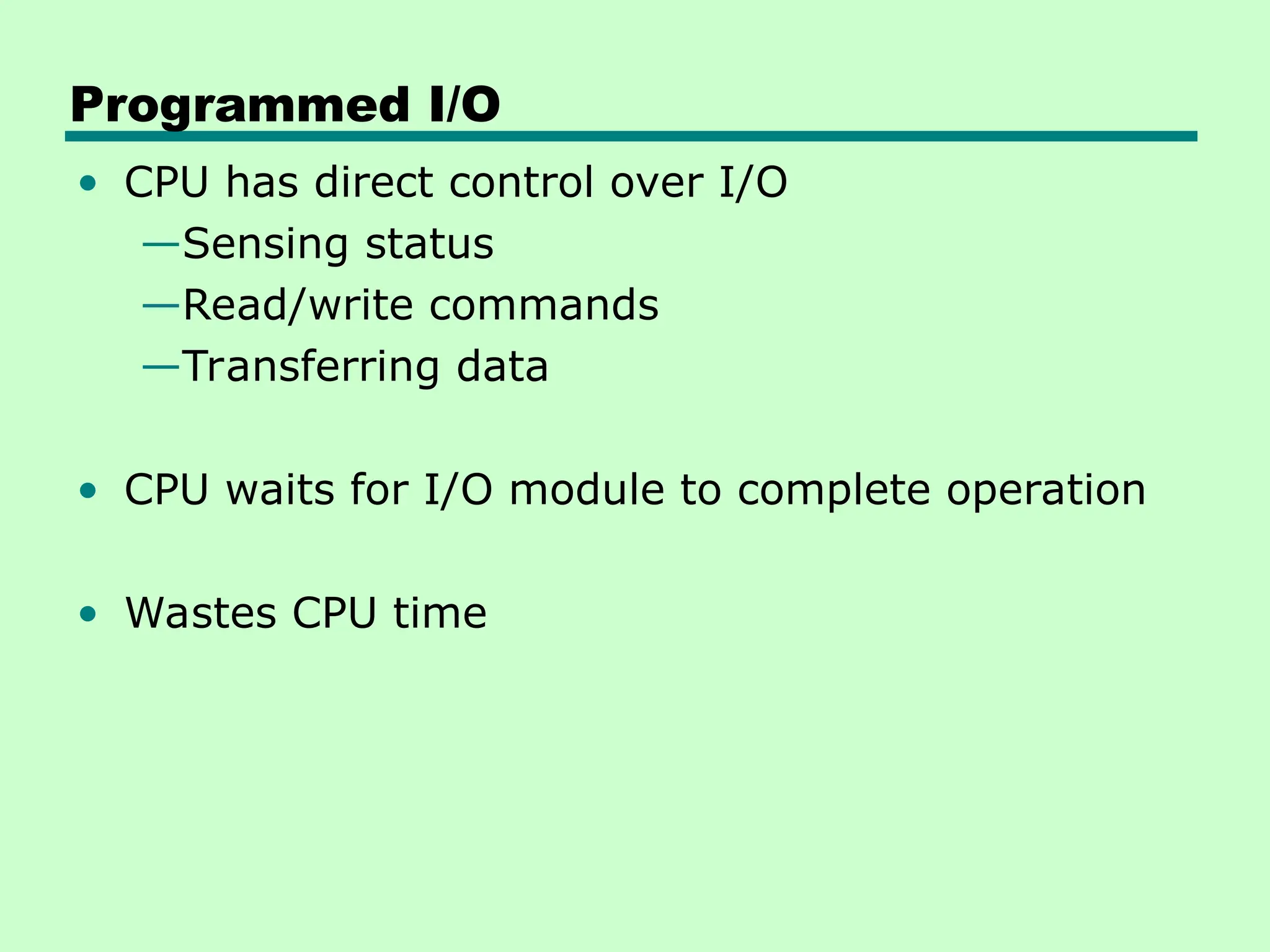
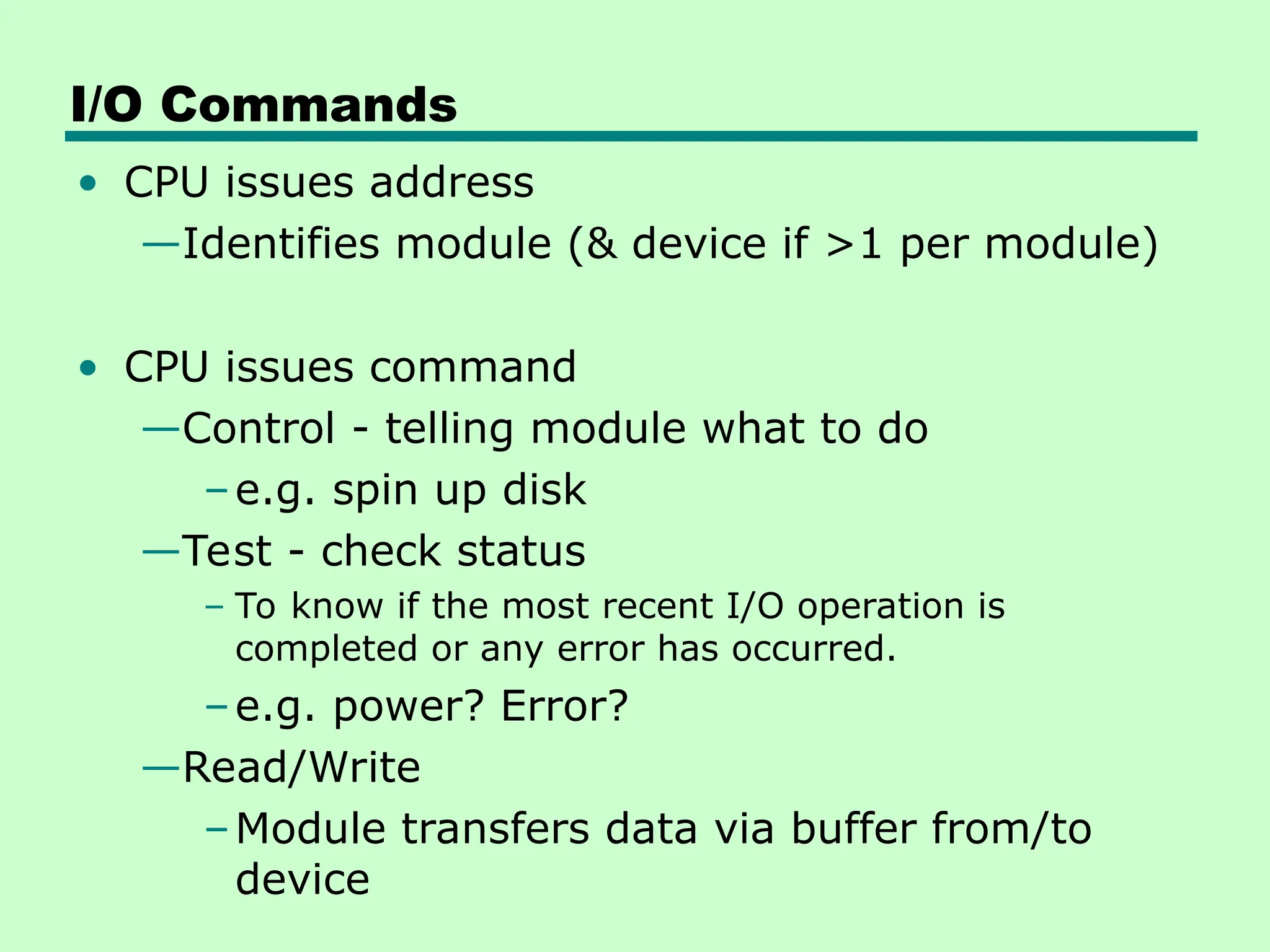
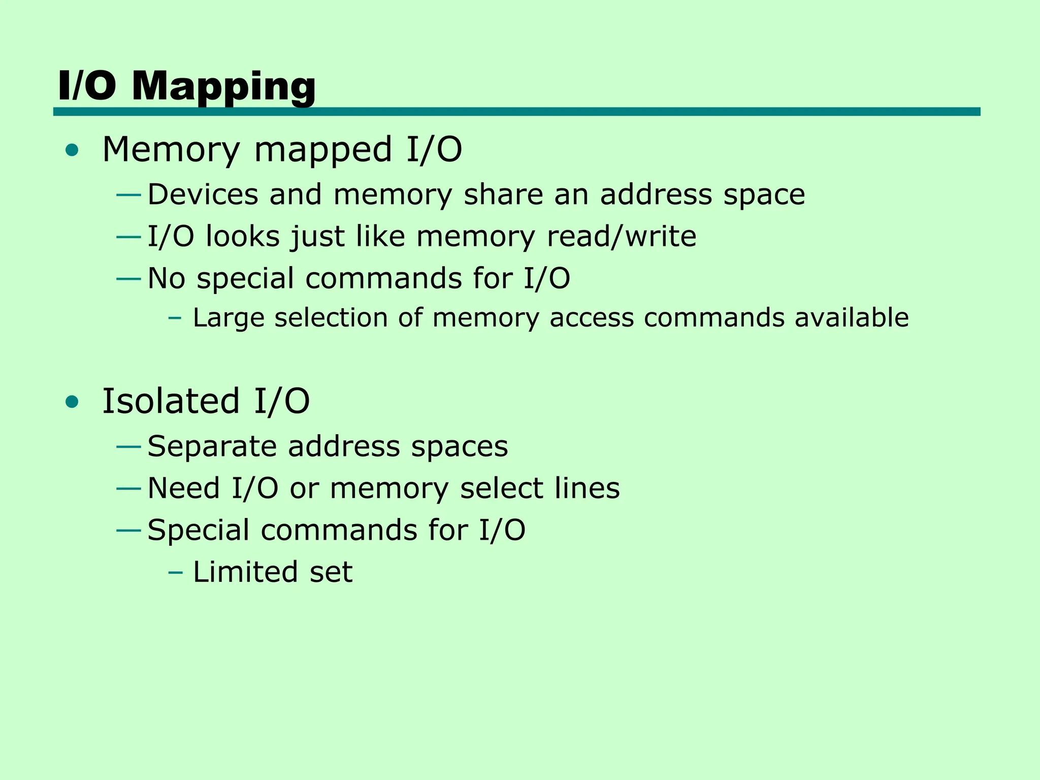
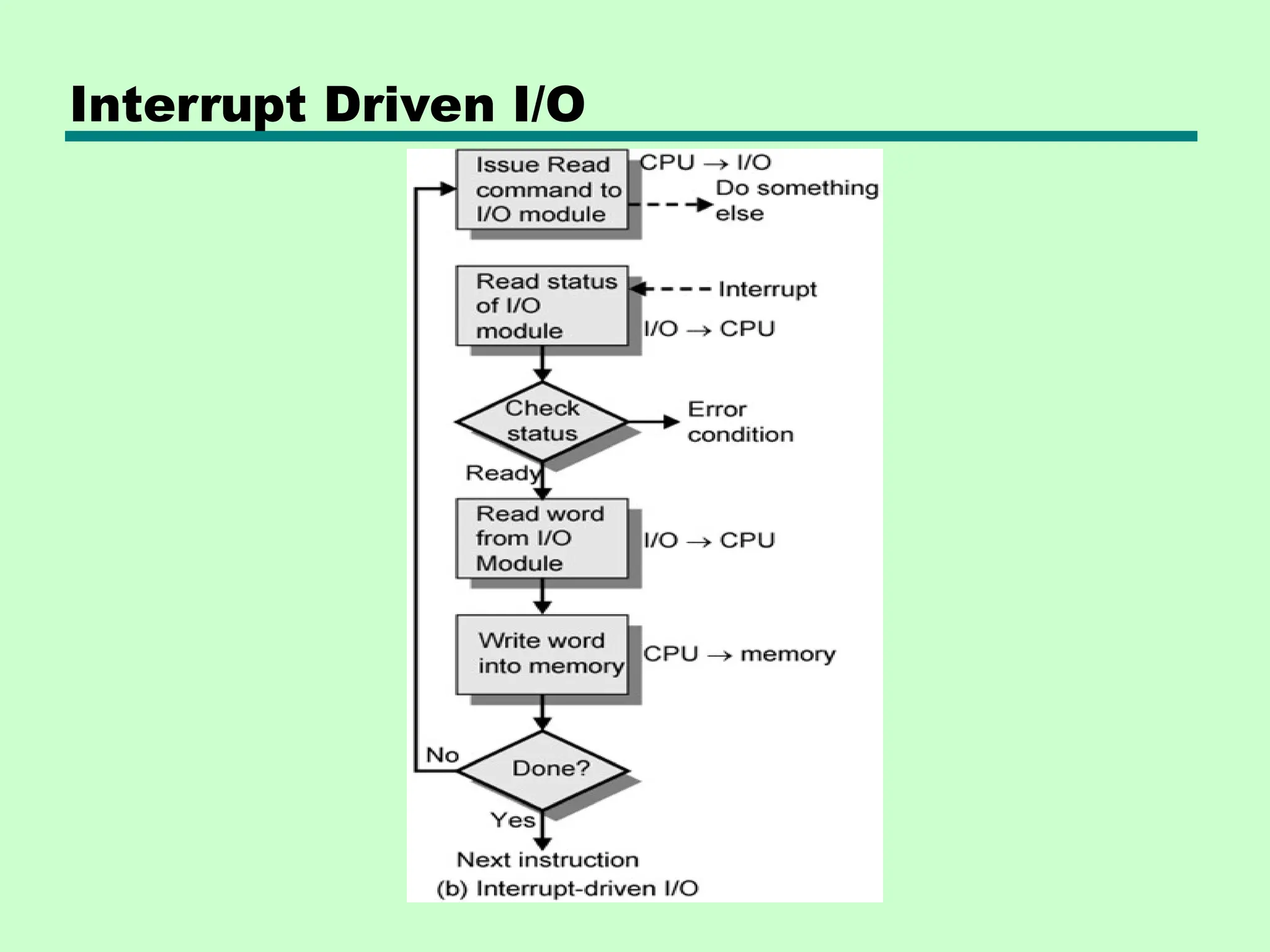
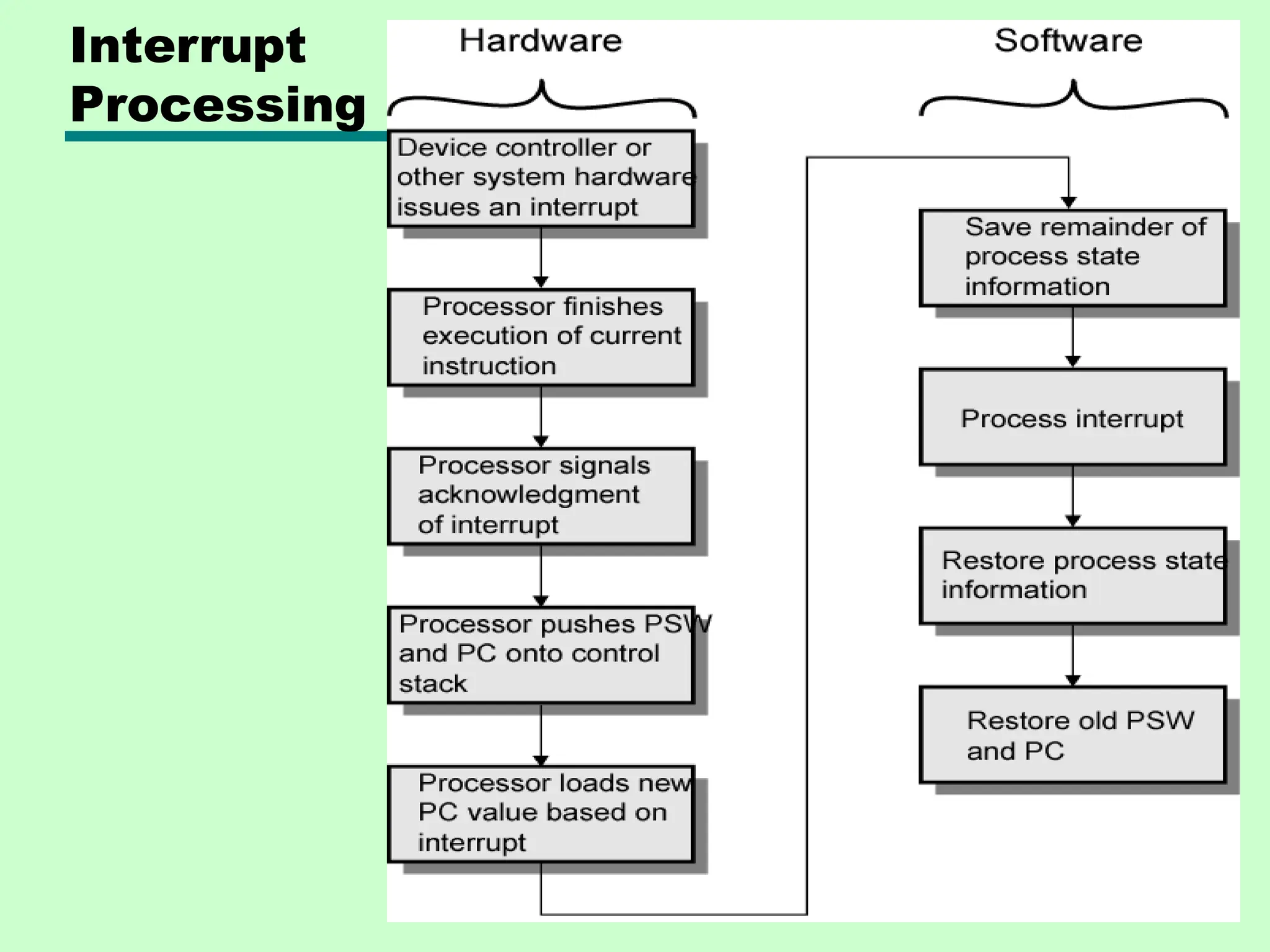
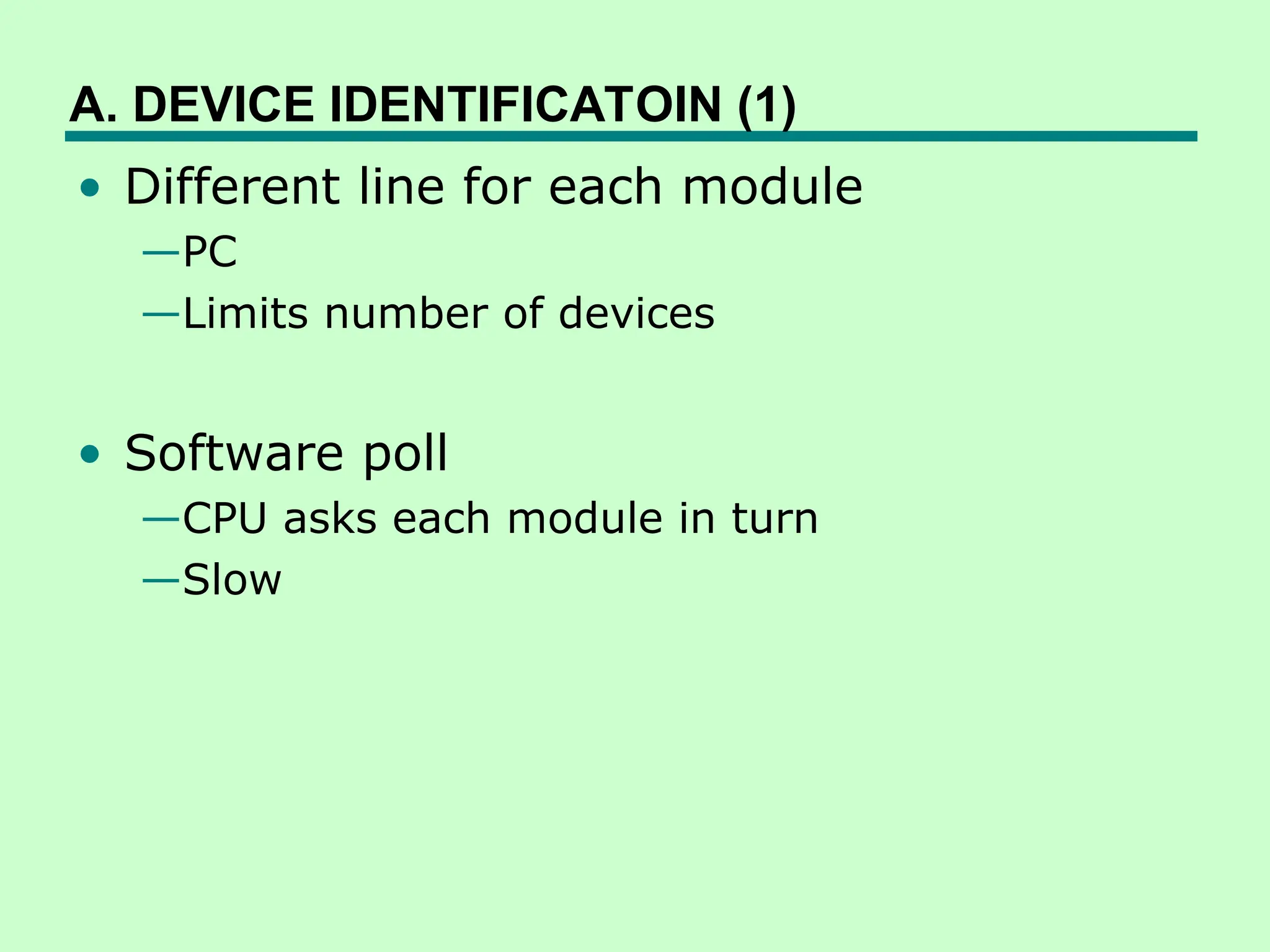
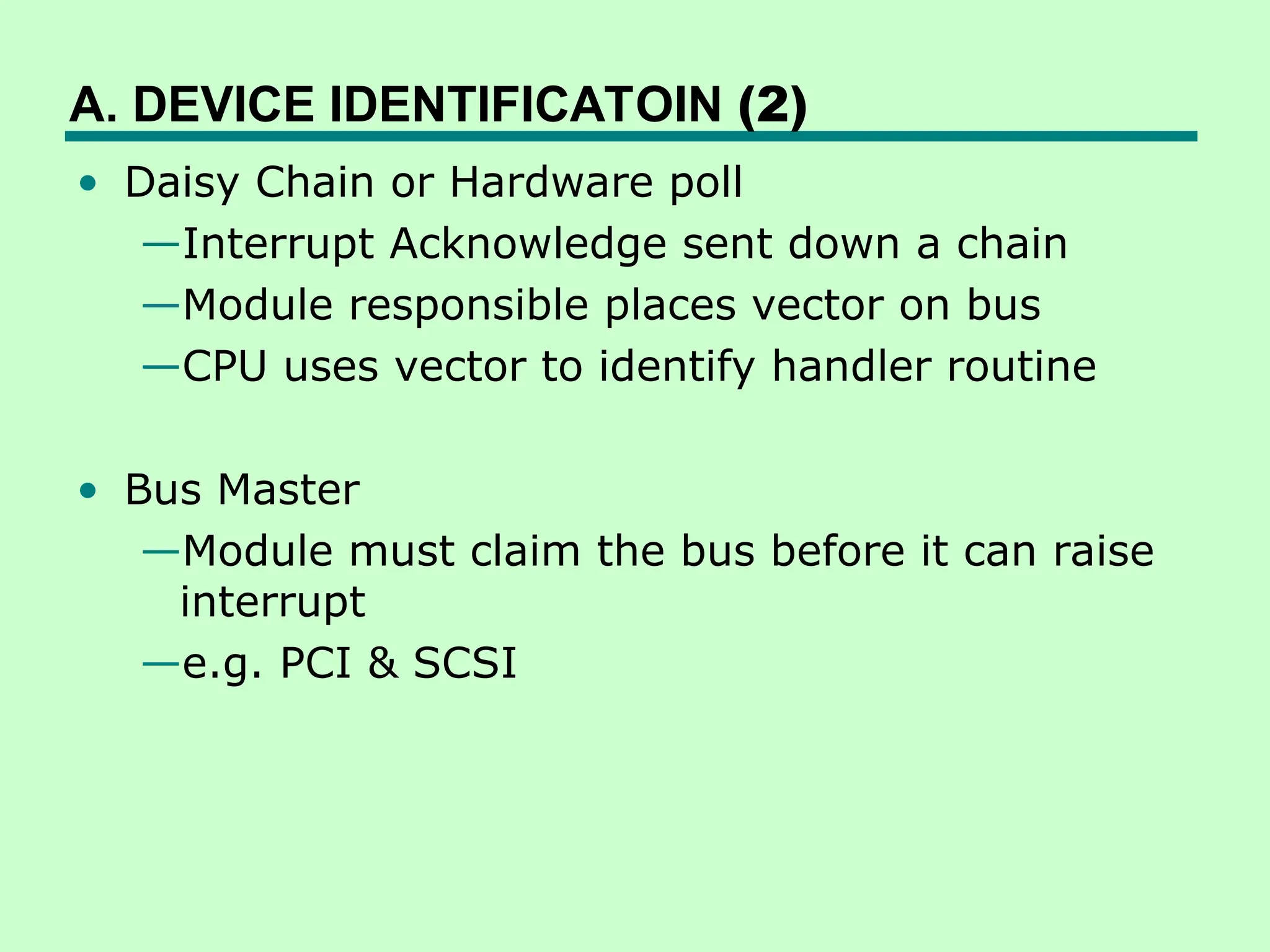
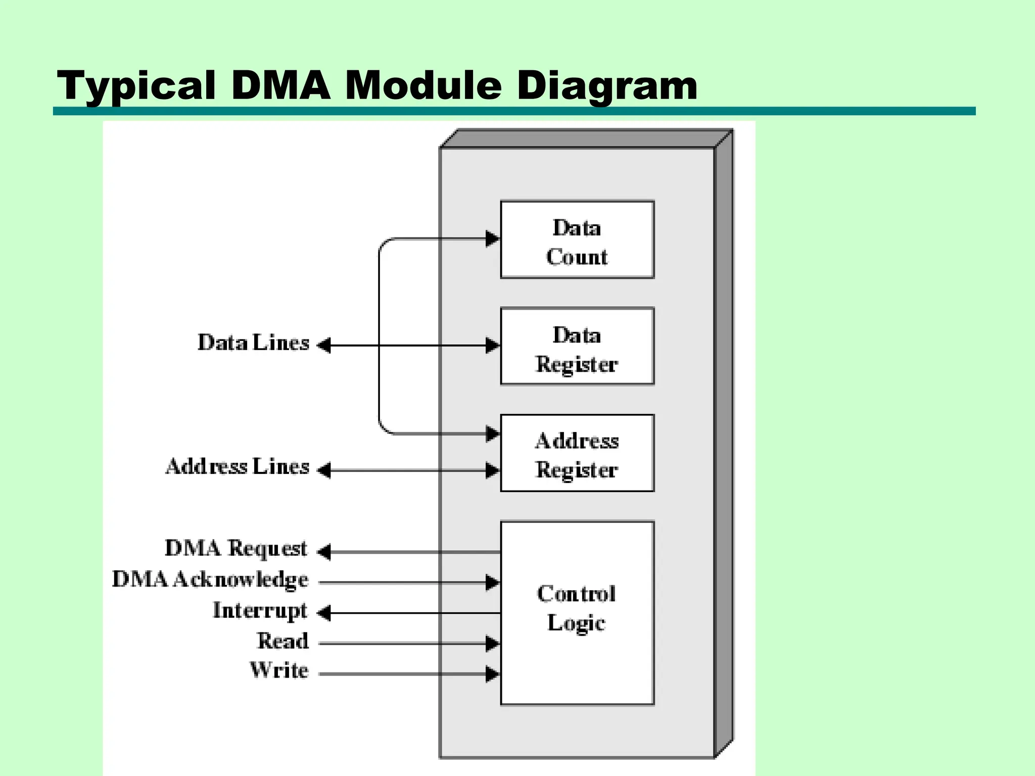
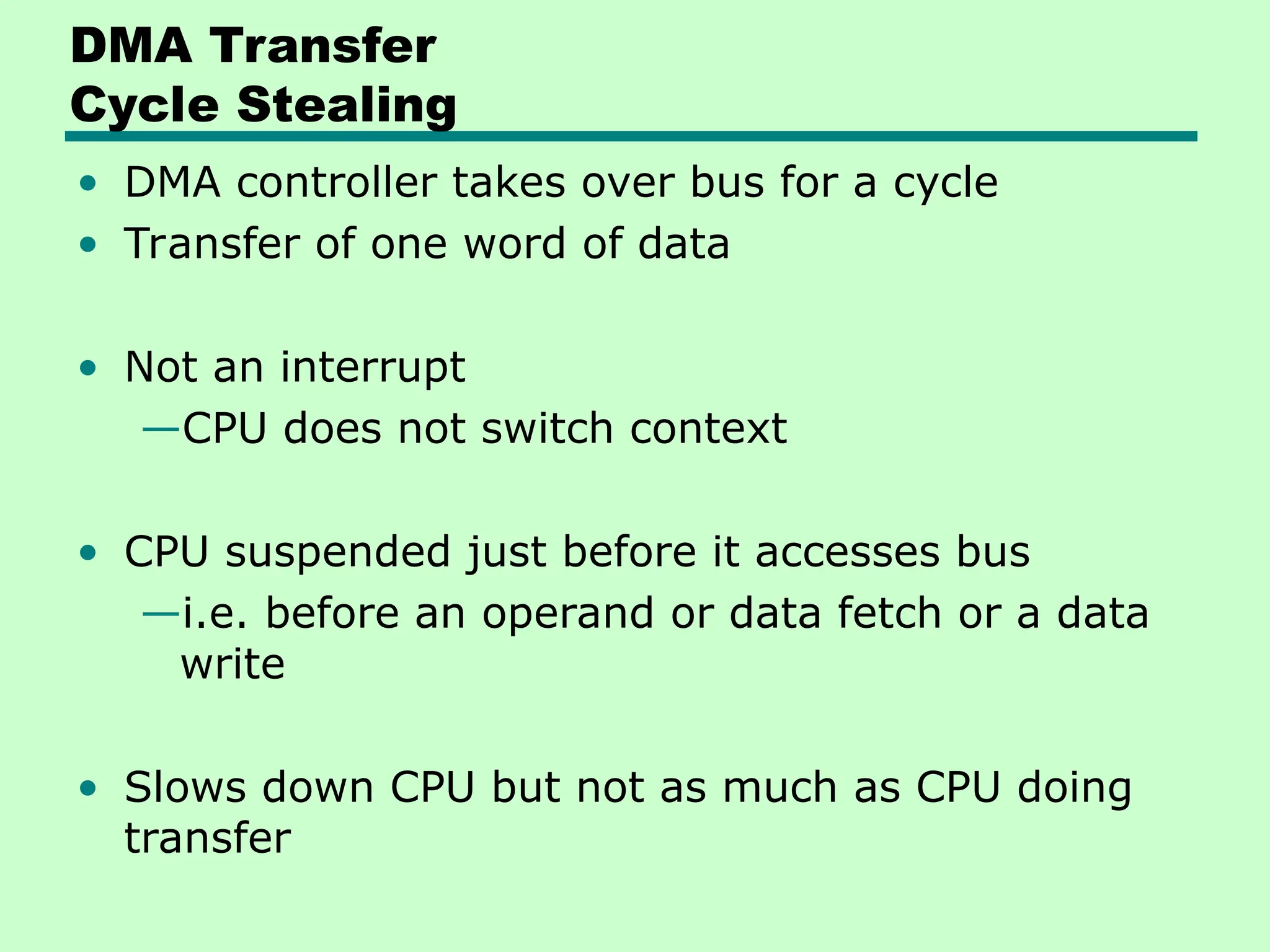
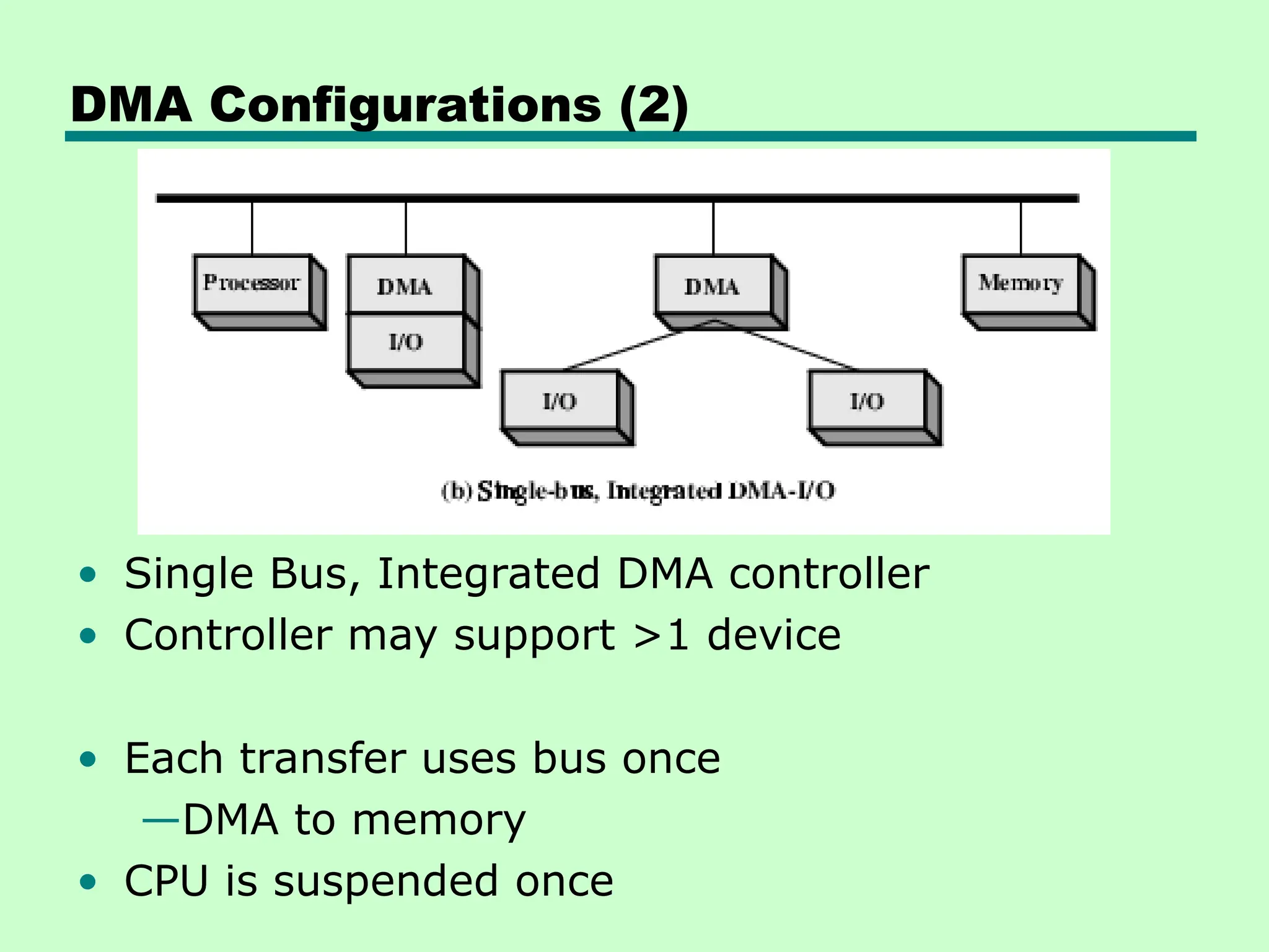
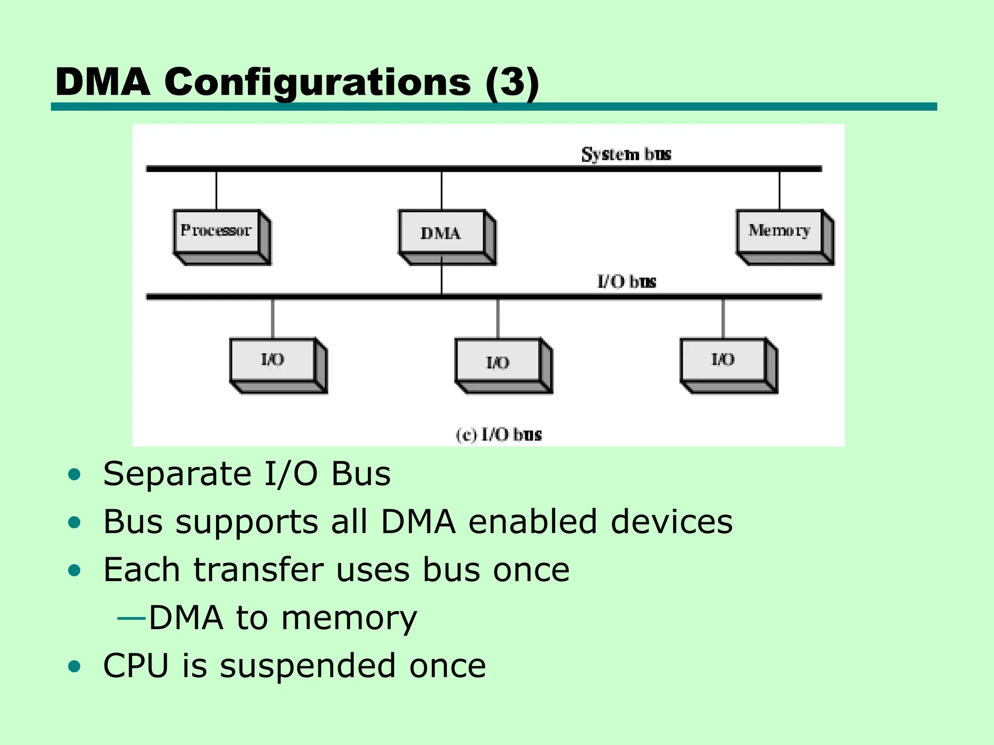
KEMBAR78
Input / Output organization of computer architecture | PPT
Unit 6
Input/ Output Organization
Input/Output Problems
• Wide variety of peripherals
—Delivering different amounts of data
—At different speeds
—In different formats
• All slower than CPU and RAM
• Need I/O modules
Input / Output Module
• Interface to CPU and Memory
• Interface to one or more peripherals
Generic Model of I/O Module
External Device Block Diagram
• Human readable
—Screen
—printer
• Machine readable
—Monitoring
—control
• Communication
—Modem
—Network
Interface Card
(NIC)
I/O Module Function
• Control & Timing
• CPU Communication
• Device Communication
• Data Buffering
• Error Detection
I/O Steps
• CPU checks I/O module device status
• I/O module returns status
• If ready, CPU requests data transfer
• I/O module gets data from device
• I/O module transfers data to CPU
• Variations for output, DMA, etc.
I/O Module Diagram
I/O Module Decisions
• Hide or expose device properties to CPU
• Support multiple or single device
• Control device functions or run off for CPU
• Also O/S decisions
Input Output Techniques
• Programmed
• Interrupt driven
• Direct Memory Access (DMA)
Three Techniques for
Input of a Block of Data
Programmed Input Output
Programmed I/O
• CPU has direct control over I/O
—Sensing status
—Read/write commands
—Transferring data
• CPU waits for I/O module to complete operation
• Wastes CPU time
Programmed I/O - detail
• CPU requests I/O operation
• I/O module performs operation
• I/O module sets status bits
• CPU checks status bits periodically
• I/O module does not inform CPU directly
• I/O module does not interrupt CPU
• CPU may wait or come back later
I/O Commands
• CPU issues address
—Identifies module (& device if >1 per module)
• CPU issues command
—Control - telling module what to do
–e.g. spin up disk
—Test - check status
– To know if the most recent I/O operation is
completed or any error has occurred.
–e.g. power? Error?
—Read/Write
–Module transfers data via buffer from/to
device
I/O Mapping
• Memory mapped I/O
—Devices and memory share an address space
—I/O looks just like memory read/write
—No special commands for I/O
– Large selection of memory access commands available
• Isolated I/O
—Separate address spaces
—Need I/O or memory select lines
—Special commands for I/O
– Limited set
Interrupt Driven I/O
• Overcomes CPU waiting
• No repeated CPU checking of device
• I/O module interrupts when ready
Interrupt Driven I/O
Basic Operation
• CPU issues read command
• I/O module gets data from peripheral while CPU
does other work
• I/O module interrupts CPU
• CPU requests data
• I/O module transfers data
Interrupt
Processing
CPU Viewpoint
• Issue read command
• Do other work
• Check for interrupt at end of each instruction cycle
• If interrupted:-
—Save context (registers)
—Process interrupt
–Fetch data & store
• See Operating Systems observations
Design Issues
• How do you identify the module issuing the
interrupt?
• How do you deal with multiple interrupts?
—i.e. an interrupt handler being interrupted
A. DEVICE IDENTIFICATOIN (1)
• Different line for each module
—PC
—Limits number of devices
• Software poll
—CPU asks each module in turn
—Slow
A. DEVICE IDENTIFICATOIN (2)
• Daisy Chain or Hardware poll
—Interrupt Acknowledge sent down a chain
—Module responsible places vector on bus
—CPU uses vector to identify handler routine
• Bus Master
—Module must claim the bus before it can raise
interrupt
—e.g. PCI & SCSI
B. Handling Multiple Interrupts
• Each interrupt line has a priority
• Higher priority lines can interrupt lower priority
lines
• If bus mastering only current master can
interrupt
Example - PC Bus
• 80x86 has one interrupt line
• 8086 based systems use one 8259A interrupt
controller
• 8259A has 8 interrupt lines
Direct Memory Access
• Interrupt driven and programmed I/O require
active CPU intervention
—Transfer rate is limited
—CPU is tied up
• DMA is the answer
DMA Function
• Additional Module (hardware) on bus
• DMA controller takes over from CPU for I/O
Typical DMA Module Diagram
DMA Operation
• CPU tells DMA controller:-
—Read/Write
—Device address
—Starting address of memory block for data
—Amount of data to be transferred
• CPU carries on with other work
• DMA controller deals with transfer
• DMA controller sends interrupt when finished
DMA Transfer
Cycle Stealing
• DMA controller takes over bus for a cycle
• Transfer of one word of data
• Not an interrupt
—CPU does not switch context
• CPU suspended just before it accesses bus
—i.e. before an operand or data fetch or a data
write
• Slows down CPU but not as much as CPU doing
transfer
DMA Configurations (1)
• Single Bus, Detached DMA controller
• Each transfer uses bus twice
—I/O to DMA then DMA to memory
• CPU is suspended twice
DMA Configurations (2)
• Single Bus, Integrated DMA controller
• Controller may support >1 device
• Each transfer uses bus once
—DMA to memory
• CPU is suspended once
DMA Configurations (3)
• Separate I/O Bus
• Bus supports all DMA enabled devices
• Each transfer uses bus once
—DMA to memory
• CPU is suspended once

Input / Output organization of computer architecture

  • 1.
  • 2.
    Input/Output Problems • Widevariety of peripherals —Delivering different amounts of data —At different speeds —In different formats • All slower than CPU and RAM • Need I/O modules Input / Output Module • Interface to CPU and Memory • Interface to one or more peripherals
  • 3.
    Generic Model ofI/O Module
  • 4.
    External Device BlockDiagram • Human readable —Screen —printer • Machine readable —Monitoring —control • Communication —Modem —Network Interface Card (NIC)
  • 5.
    I/O Module Function •Control & Timing • CPU Communication • Device Communication • Data Buffering • Error Detection
  • 6.
    I/O Steps • CPUchecks I/O module device status • I/O module returns status • If ready, CPU requests data transfer • I/O module gets data from device • I/O module transfers data to CPU • Variations for output, DMA, etc.
  • 7.
  • 8.
    I/O Module Decisions •Hide or expose device properties to CPU • Support multiple or single device • Control device functions or run off for CPU • Also O/S decisions Input Output Techniques • Programmed • Interrupt driven • Direct Memory Access (DMA)
  • 9.
    Three Techniques for Inputof a Block of Data
  • 10.
  • 11.
    Programmed I/O • CPUhas direct control over I/O —Sensing status —Read/write commands —Transferring data • CPU waits for I/O module to complete operation • Wastes CPU time
  • 12.
    Programmed I/O -detail • CPU requests I/O operation • I/O module performs operation • I/O module sets status bits • CPU checks status bits periodically • I/O module does not inform CPU directly • I/O module does not interrupt CPU • CPU may wait or come back later
  • 13.
    I/O Commands • CPUissues address —Identifies module (& device if >1 per module) • CPU issues command —Control - telling module what to do –e.g. spin up disk —Test - check status – To know if the most recent I/O operation is completed or any error has occurred. –e.g. power? Error? —Read/Write –Module transfers data via buffer from/to device
  • 14.
    I/O Mapping • Memorymapped I/O —Devices and memory share an address space —I/O looks just like memory read/write —No special commands for I/O – Large selection of memory access commands available • Isolated I/O —Separate address spaces —Need I/O or memory select lines —Special commands for I/O – Limited set
  • 15.
    Interrupt Driven I/O •Overcomes CPU waiting • No repeated CPU checking of device • I/O module interrupts when ready
  • 16.
  • 17.
    Interrupt Driven I/O BasicOperation • CPU issues read command • I/O module gets data from peripheral while CPU does other work • I/O module interrupts CPU • CPU requests data • I/O module transfers data
  • 18.
  • 19.
    CPU Viewpoint • Issueread command • Do other work • Check for interrupt at end of each instruction cycle • If interrupted:- —Save context (registers) —Process interrupt –Fetch data & store • See Operating Systems observations Design Issues • How do you identify the module issuing the interrupt? • How do you deal with multiple interrupts? —i.e. an interrupt handler being interrupted
  • 20.
    A. DEVICE IDENTIFICATOIN(1) • Different line for each module —PC —Limits number of devices • Software poll —CPU asks each module in turn —Slow
  • 21.
    A. DEVICE IDENTIFICATOIN(2) • Daisy Chain or Hardware poll —Interrupt Acknowledge sent down a chain —Module responsible places vector on bus —CPU uses vector to identify handler routine • Bus Master —Module must claim the bus before it can raise interrupt —e.g. PCI & SCSI
  • 22.
    B. Handling MultipleInterrupts • Each interrupt line has a priority • Higher priority lines can interrupt lower priority lines • If bus mastering only current master can interrupt Example - PC Bus • 80x86 has one interrupt line • 8086 based systems use one 8259A interrupt controller • 8259A has 8 interrupt lines
  • 23.
    Direct Memory Access •Interrupt driven and programmed I/O require active CPU intervention —Transfer rate is limited —CPU is tied up • DMA is the answer DMA Function • Additional Module (hardware) on bus • DMA controller takes over from CPU for I/O
  • 24.
  • 25.
    DMA Operation • CPUtells DMA controller:- —Read/Write —Device address —Starting address of memory block for data —Amount of data to be transferred • CPU carries on with other work • DMA controller deals with transfer • DMA controller sends interrupt when finished
  • 26.
    DMA Transfer Cycle Stealing •DMA controller takes over bus for a cycle • Transfer of one word of data • Not an interrupt —CPU does not switch context • CPU suspended just before it accesses bus —i.e. before an operand or data fetch or a data write • Slows down CPU but not as much as CPU doing transfer
  • 27.
    DMA Configurations (1) •Single Bus, Detached DMA controller • Each transfer uses bus twice —I/O to DMA then DMA to memory • CPU is suspended twice
  • 28.
    DMA Configurations (2) •Single Bus, Integrated DMA controller • Controller may support >1 device • Each transfer uses bus once —DMA to memory • CPU is suspended once
  • 29.
    DMA Configurations (3) •Separate I/O Bus • Bus supports all DMA enabled devices • Each transfer uses bus once —DMA to memory • CPU is suspended once