The document discusses sequence diagrams and their components. A sequence diagram models the behavior of a use case by showing the sequence of messages passed between objects over time. It contains active objects along the top representing actors and classes, connected by messages that illustrate communication. Other elements include lifelines, activation boxes to indicate focus of control, and control information like conditions and iterations. The document provides examples and steps for constructing a sequence diagram based on a use case.
Introduction to use cases and sequence diagrams; covers interaction models and sequence diagrams for illustrating object interactions over time.
Detailed explanation of sequence diagrams including members, lifelines, active objects, and actors, facilitating understanding of sequence interactions.
Focus on messages in sequence diagrams, covering types, syntax, and methods for effective interaction representation.
Descriptions of lifelines, control flow, conditions, and how to signify object creation and destruction in sequence diagrams.
Guideline outlining the steps necessary to build a sequence diagram, including actor identification, message layout, and validation.
Provides a concluding sequence diagram example and thanks for the presentation, summarizing the key elements of the discussed content.
Slide 2
Interaction Diagrams
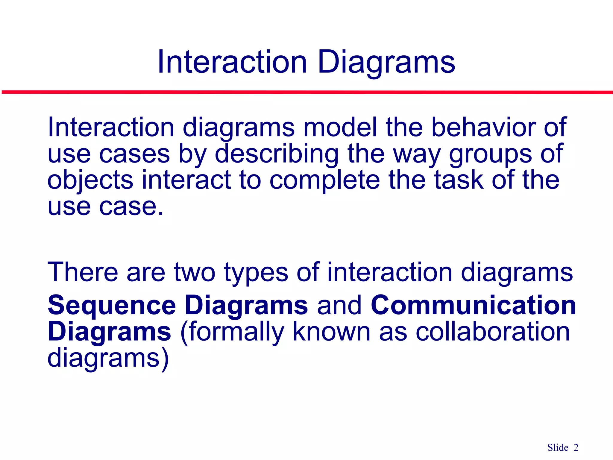
qInteraction diagrams model the behavior of
use cases by describing the way groups of
objects interact to complete the task of the
use case.
q There are two types of interaction diagrams
q Sequence Diagrams and Communication
Diagrams (formally known as collaboration
diagrams)
3.
Slide 3
Interaction Diagrams
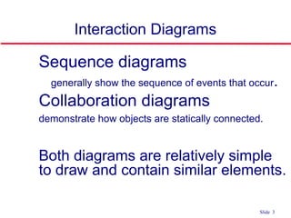
qSequence diagrams
• generally show the sequence of events that occur.
q Collaboration diagrams
demonstrate how objects are statically connected.
q Both diagrams are relatively simple
to draw and contain similar elements.
4.
Slide 4
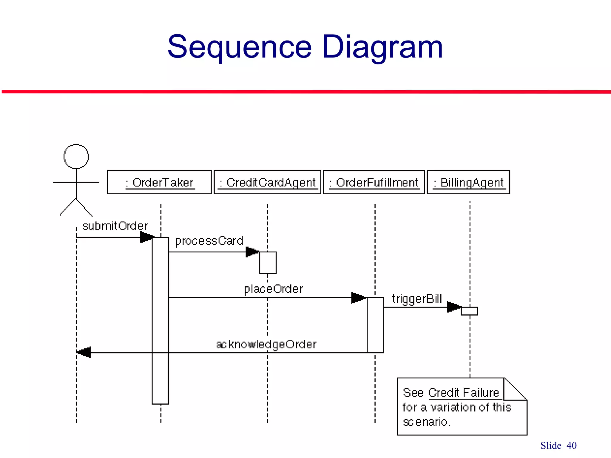
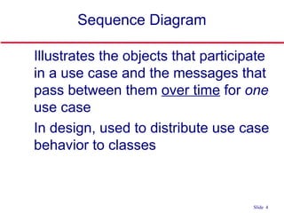
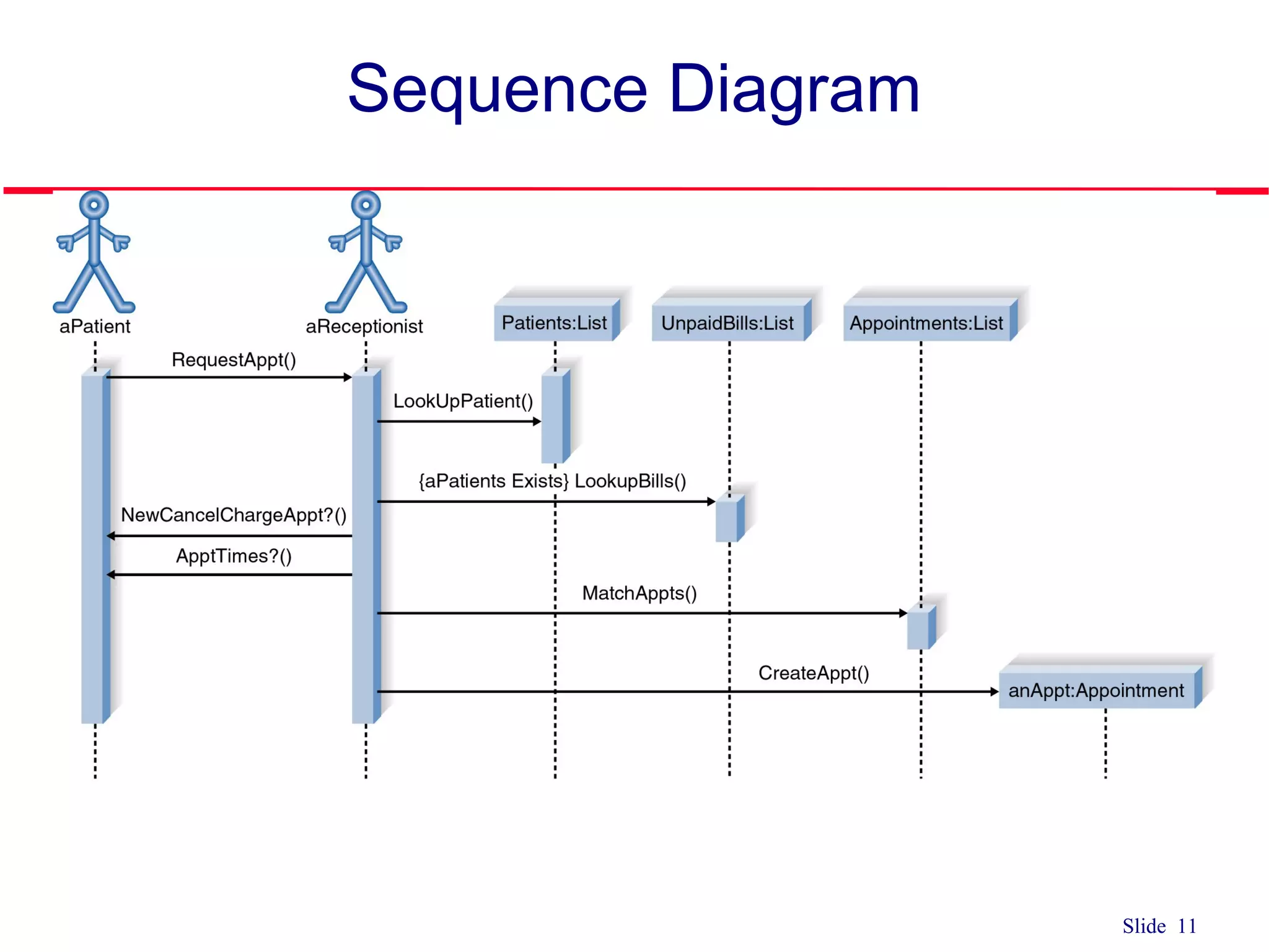
Sequence Diagram
qIllustrates the objects that participate
in a use case and the messages that
pass between them over time for one
use case
q In design, used to distribute use case
behavior to classes
Slide 6
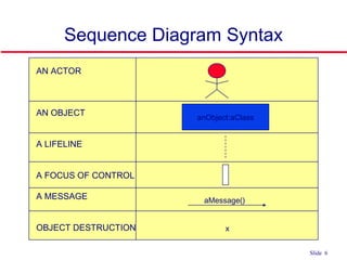
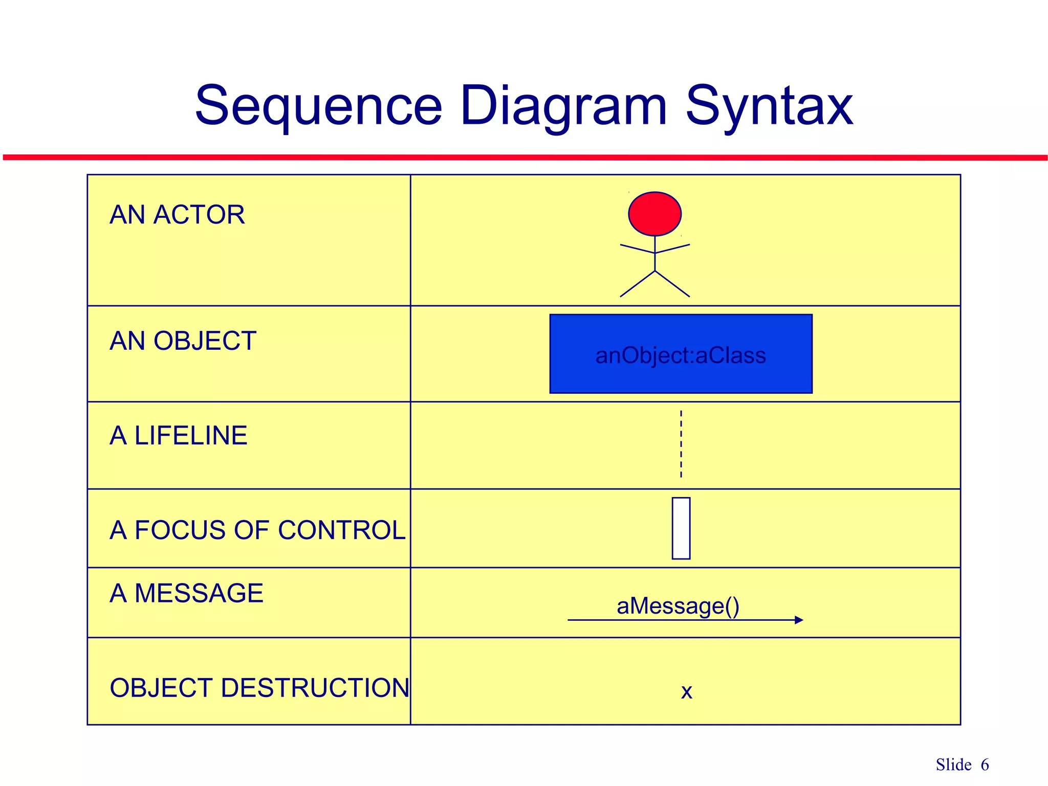
Sequence DiagramSyntax
AN ACTOR
AN OBJECT
A LIFELINE
A FOCUS OF CONTROL
A MESSAGE
OBJECT DESTRUCTION
anObject:aClass
aMessage()
x
7.
Slide 7
Sequence Diagram
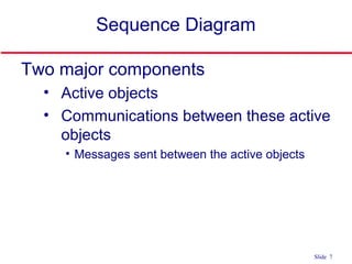
Twomajor components
• Active objects
• Communications between these active
objects
• Messages sent between the active objects
8.
Slide 8
Sequence Diagram
Activeobjects
• Any objects that play a role in the
system
• Participate by sending and/or receiving
messages
• Placed across the top of the diagram
• Can be:
• An actor (from the use case diagram)
• Object/class (from the class diagram) within the
system
9.
Slide 9
Active Objects
Object
•Can be any object or class that is
valid within the system
• Object naming
• Syntax
[instanceName][:className]
1. Class name only :Classname
2. Instance name only objectName
3. Instance name and class name
together object:Class
myBirthdy
:Date
10.
Slide 10
Active Objects
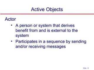
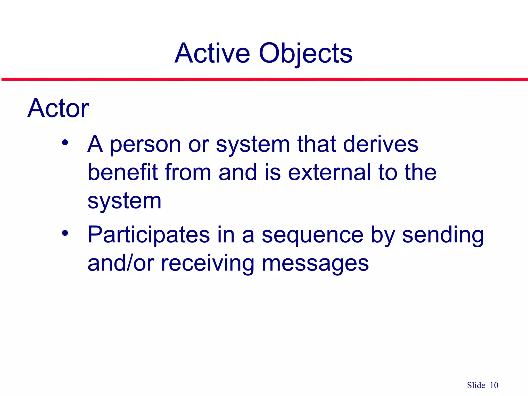
Actor
•A person or system that derives
benefit from and is external to the
system
• Participates in a sequence by sending
and/or receiving messages
Slide 12
Communications
between ActiveObjects
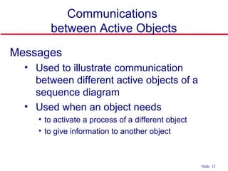
Messages
• Used to illustrate communication
between different active objects of a
sequence diagram
• Used when an object needs
• to activate a process of a different object
• to give information to another object
13.
Slide 13
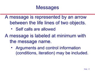
Messages
A messageis represented by an arrow
between the life lines of two objects.
• Self calls are allowed
A message is labeled at minimum with
the message name.
• Arguments and control information
(conditions, iteration) may be included.
14.
Slide 14
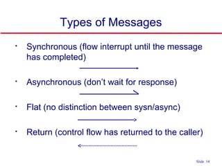
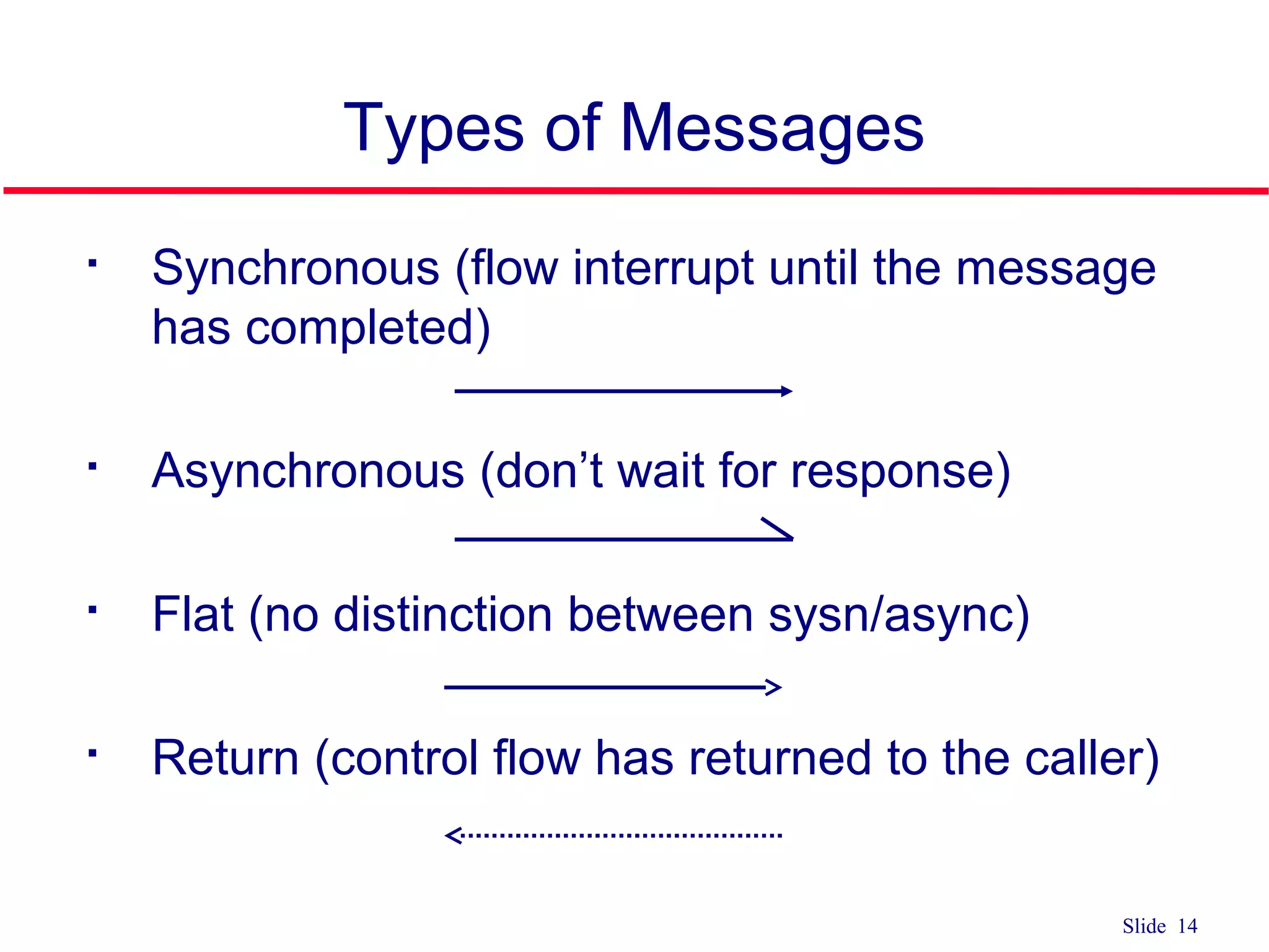
Types ofMessages
Synchronous (flow interrupt until the message
has completed)
Asynchronous (don’t wait for response)
Flat (no distinction between sysn/async)
Return (control flow has returned to the caller)
15.
Slide 15
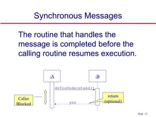
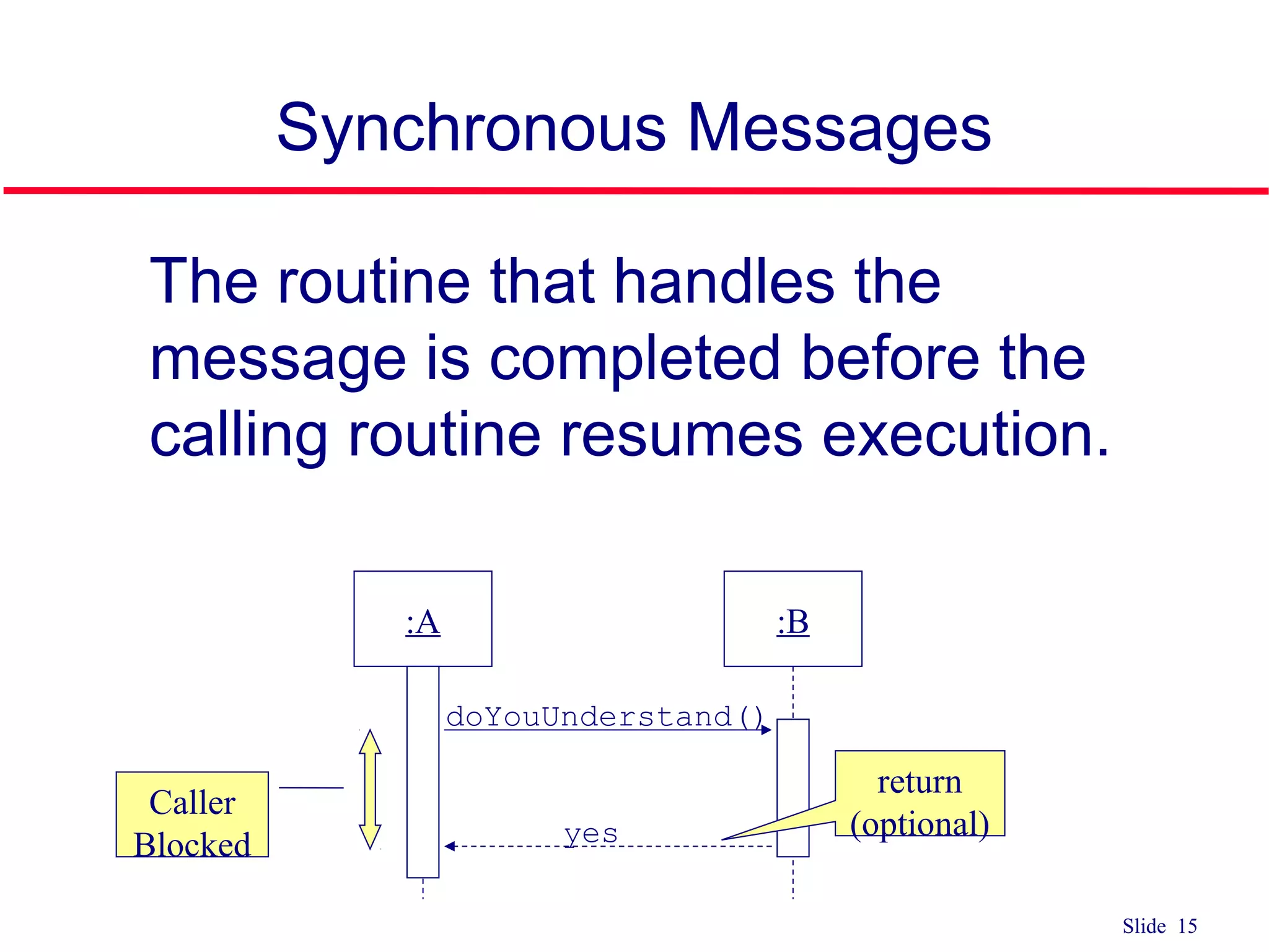
Synchronous Messages
qThe routine that handles the
message is completed before the
calling routine resumes execution.
:A :B
doYouUnderstand()
Caller
Blocked
return
(optional)yes
16.
Slide 16
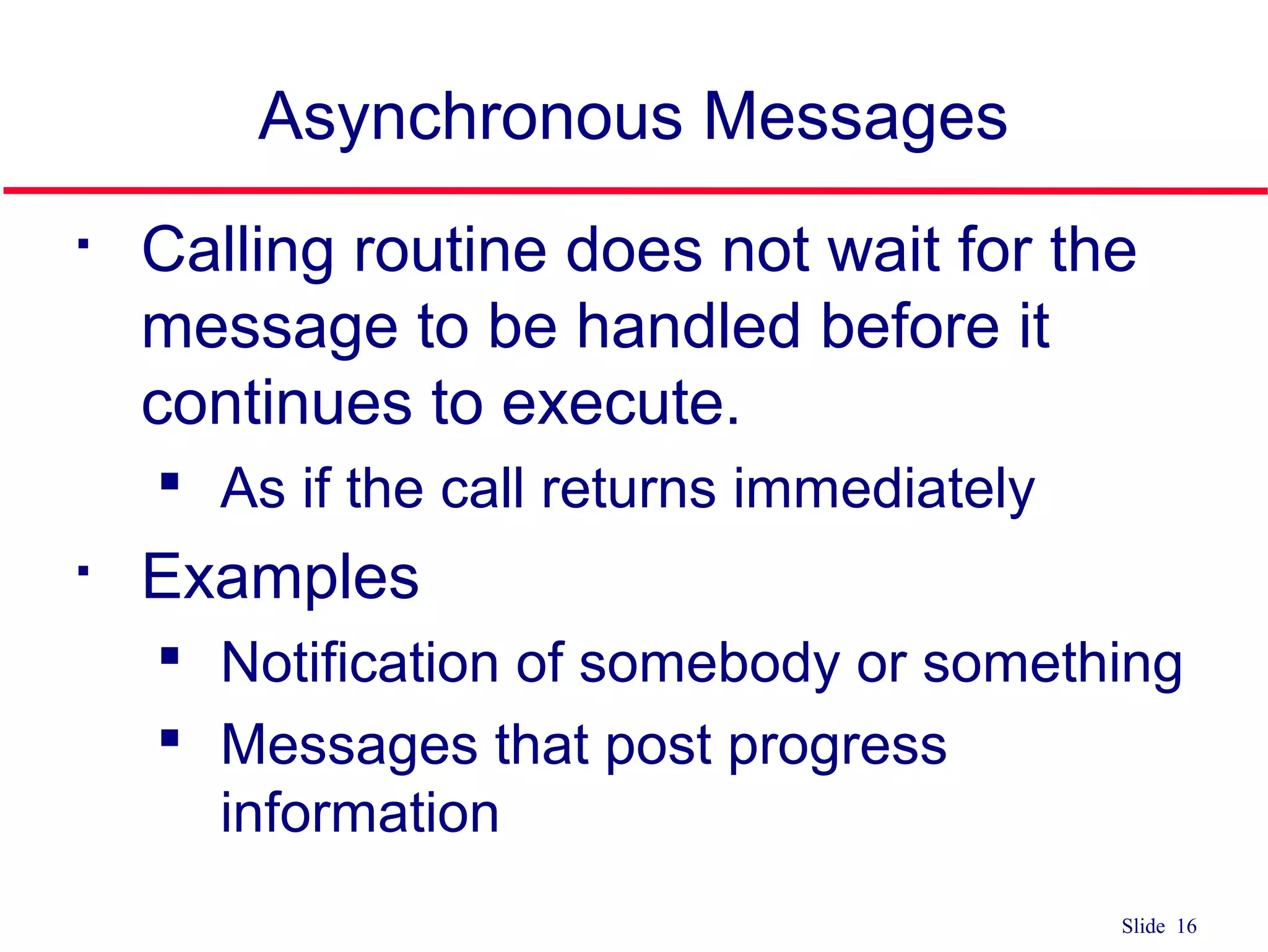
Asynchronous Messages
Callingroutine does not wait for the
message to be handled before it
continues to execute.
As if the call returns immediately
Examples
Notification of somebody or something
Messages that post progress
information
17.
Slide 17
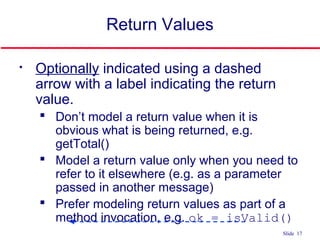
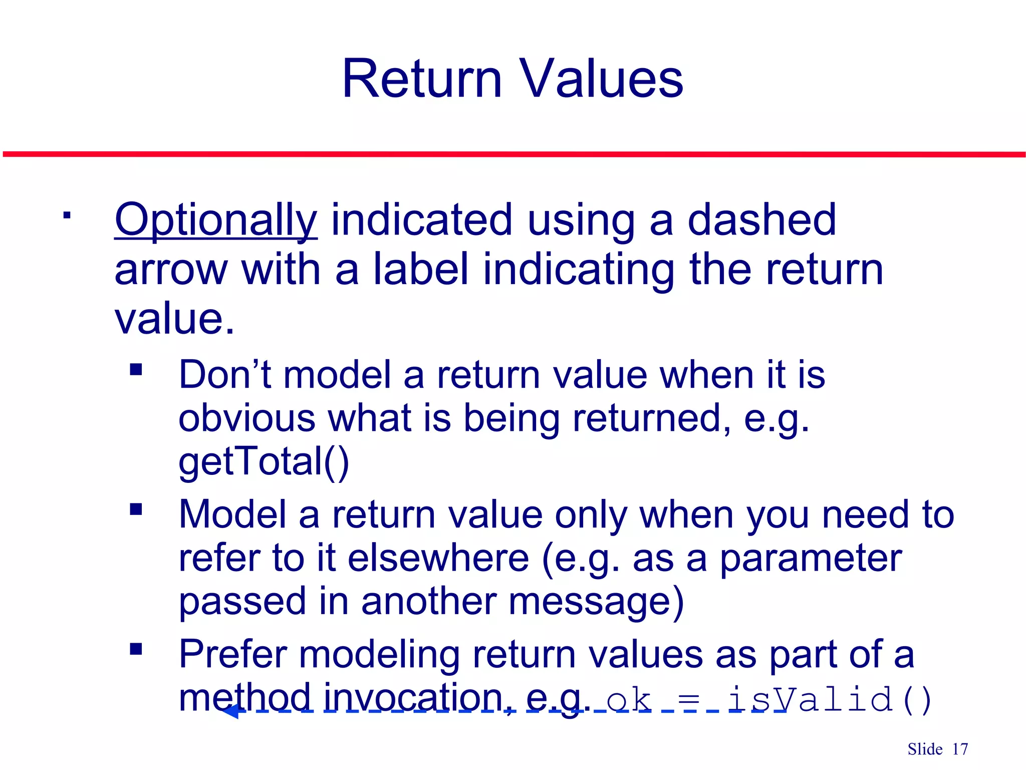
Return Values
Optionallyindicated using a dashed
arrow with a label indicating the return
value.
Don’t model a return value when it is
obvious what is being returned, e.g.
getTotal()
Model a return value only when you need to
refer to it elsewhere (e.g. as a parameter
passed in another message)
Prefer modeling return values as part of a
method invocation, e.g. ok = isValid()
Slide 19
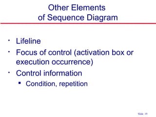
Other Elements
ofSequence Diagram
Lifeline
Focus of control (activation box or
execution occurrence)
Control information
Condition, repetition
20.
Slide 20
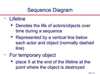
Sequence Diagram
Lifeline
Denotes the life of actors/objects over
time during a sequence
Represented by a vertical line below
each actor and object (normally dashed
line)
For temporary object
place X at the end of the lifeline at the
point where the object is destroyed
21.
Slide 21
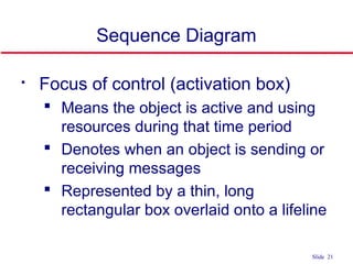
Sequence Diagram
Focusof control (activation box)
Means the object is active and using
resources during that time period
Denotes when an object is sending or
receiving messages
Represented by a thin, long
rectangular box overlaid onto a lifeline
Slide 27
Elements ofSequence Diagram
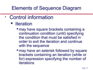
Control information
Iteration
may have square brackets containing a
continuation condition (until) specifying
the condition that must be satisfied in
order to exit the iteration and continue
with the sequence
may have an asterisk followed by square
brackets containing an iteration (while or
for) expression specifying the number of
iterations
28.
Slide 28
Control Information
Iteration
syntax: * [ ‘[‘ expression ‘]’ ]
message-label
The message is sent many times to
possibly multiple receiver objects.
*draw()
Slide 30
Sequence Diagrams
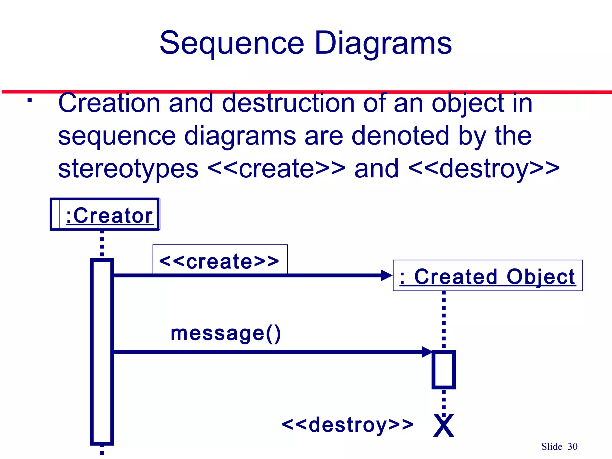
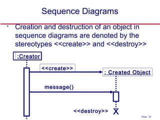
Creationand destruction of an object in
sequence diagrams are denoted by the
stereotypes <<create>> and <<destroy>>
:Creator
<<create>>
: Created Object
message()
<<destroy>> X
Slide 32
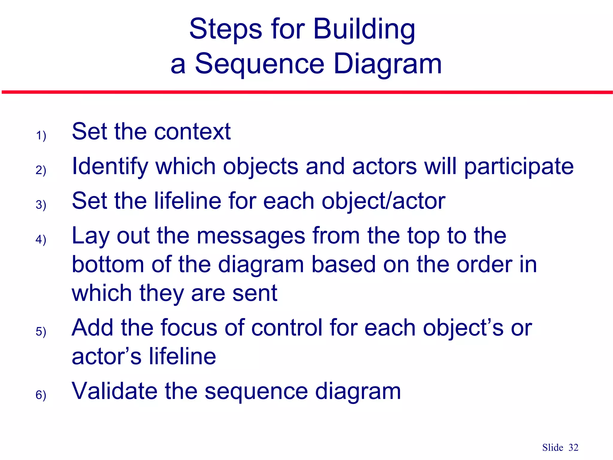
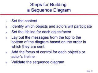
Steps forBuilding
a Sequence Diagram
1) Set the context
2) Identify which objects and actors will participate
3) Set the lifeline for each object/actor
4) Lay out the messages from the top to the
bottom of the diagram based on the order in
which they are sent
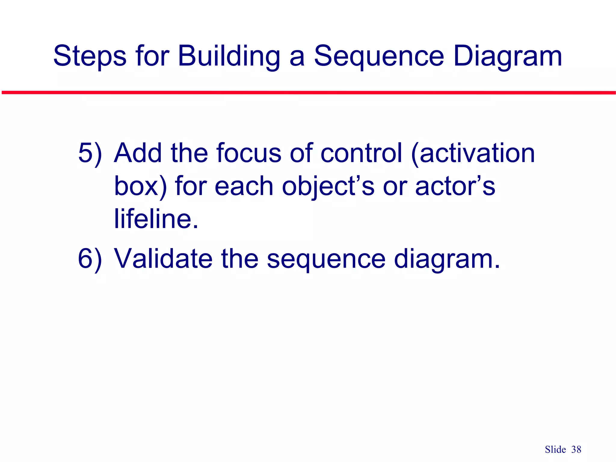
5) Add the focus of control for each object’s or
actor’s lifeline
6) Validate the sequence diagram
33.
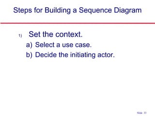
Slide 33
1) Setthe context.
a) Select a use case.
b) Decide the initiating actor.
Steps for Building a Sequence Diagram
34.
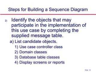
Slide 34
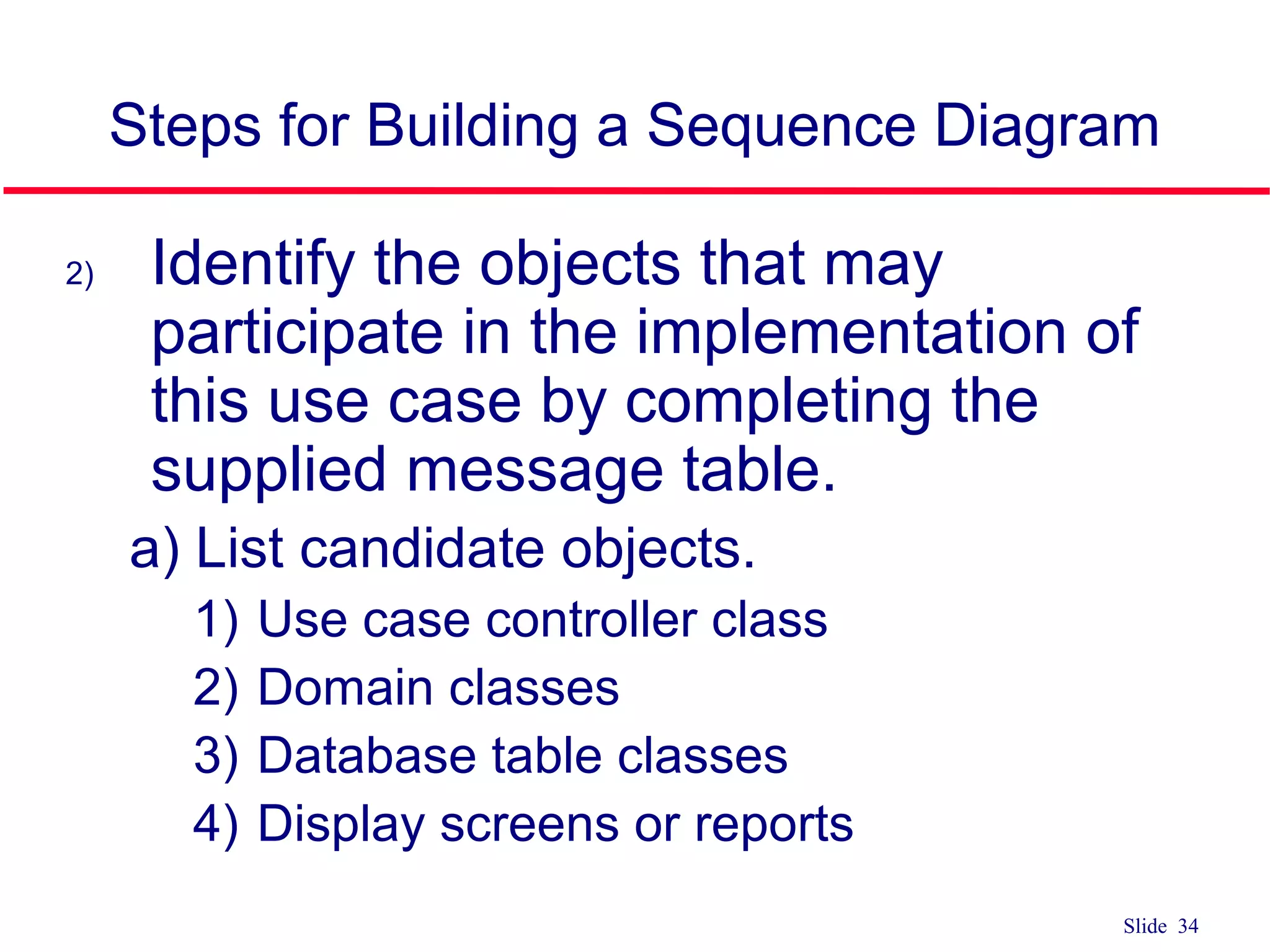
2) Identifythe objects that may
participate in the implementation of
this use case by completing the
supplied message table.
a) List candidate objects.
1) Use case controller class
2) Domain classes
3) Database table classes
4) Display screens or reports
Steps for Building a Sequence Diagram
35.
Slide 35
Steps forBuilding a Sequence Diagram
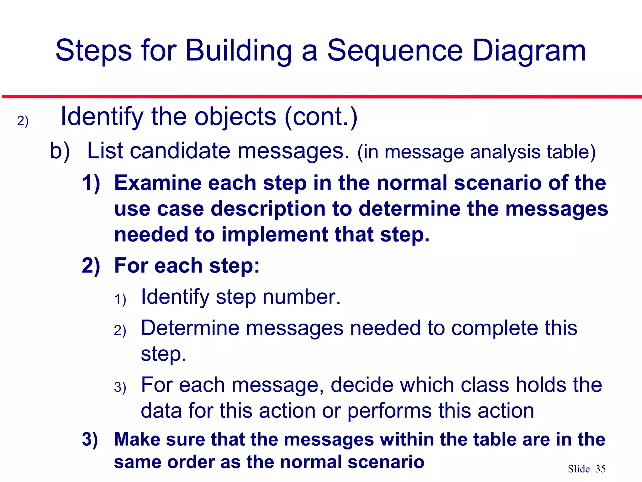
2) Identify the objects (cont.)
b) List candidate messages. (in message analysis table)
1) Examine each step in the normal scenario of the
use case description to determine the messages
needed to implement that step.
2) For each step:
1) Identify step number.
2) Determine messages needed to complete this
step.
3) For each message, decide which class holds the
data for this action or performs this action
3) Make sure that the messages within the table are in the
same order as the normal scenario
36.
Slide 36
Steps forBuilding a Sequence Diagram
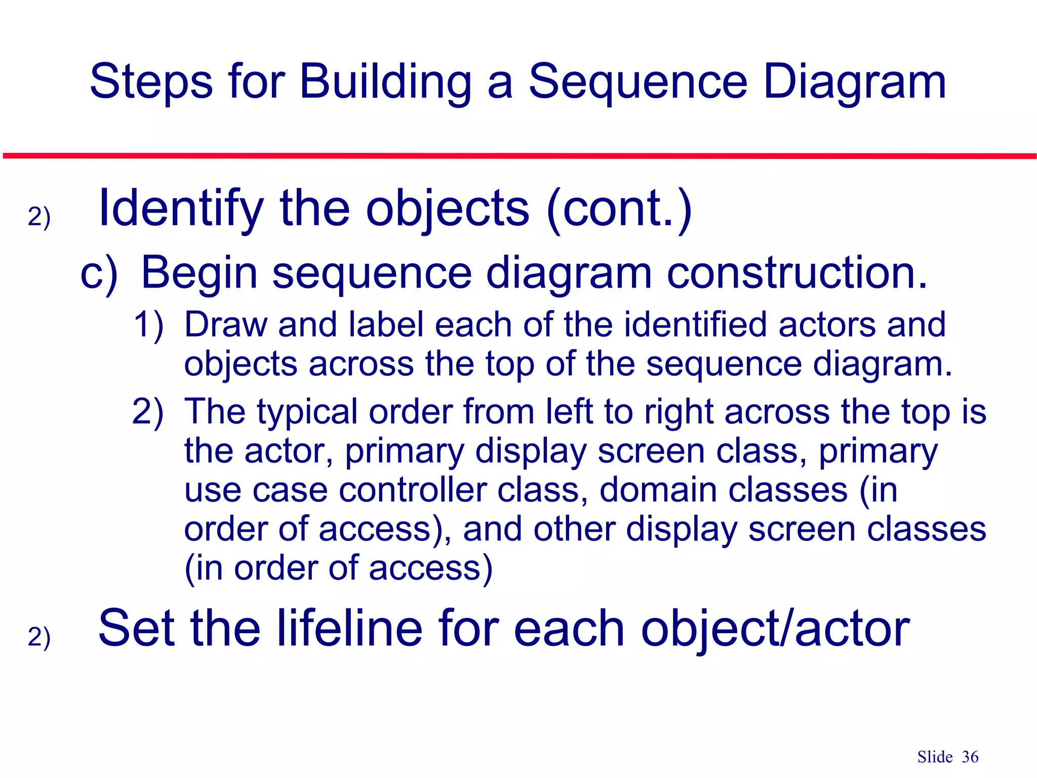
2) Identify the objects (cont.)
c) Begin sequence diagram construction.
1) Draw and label each of the identified actors and
objects across the top of the sequence diagram.
2) The typical order from left to right across the top is
the actor, primary display screen class, primary
use case controller class, domain classes (in
order of access), and other display screen classes
(in order of access)
2) Set the lifeline for each object/actor
37.
Slide 37
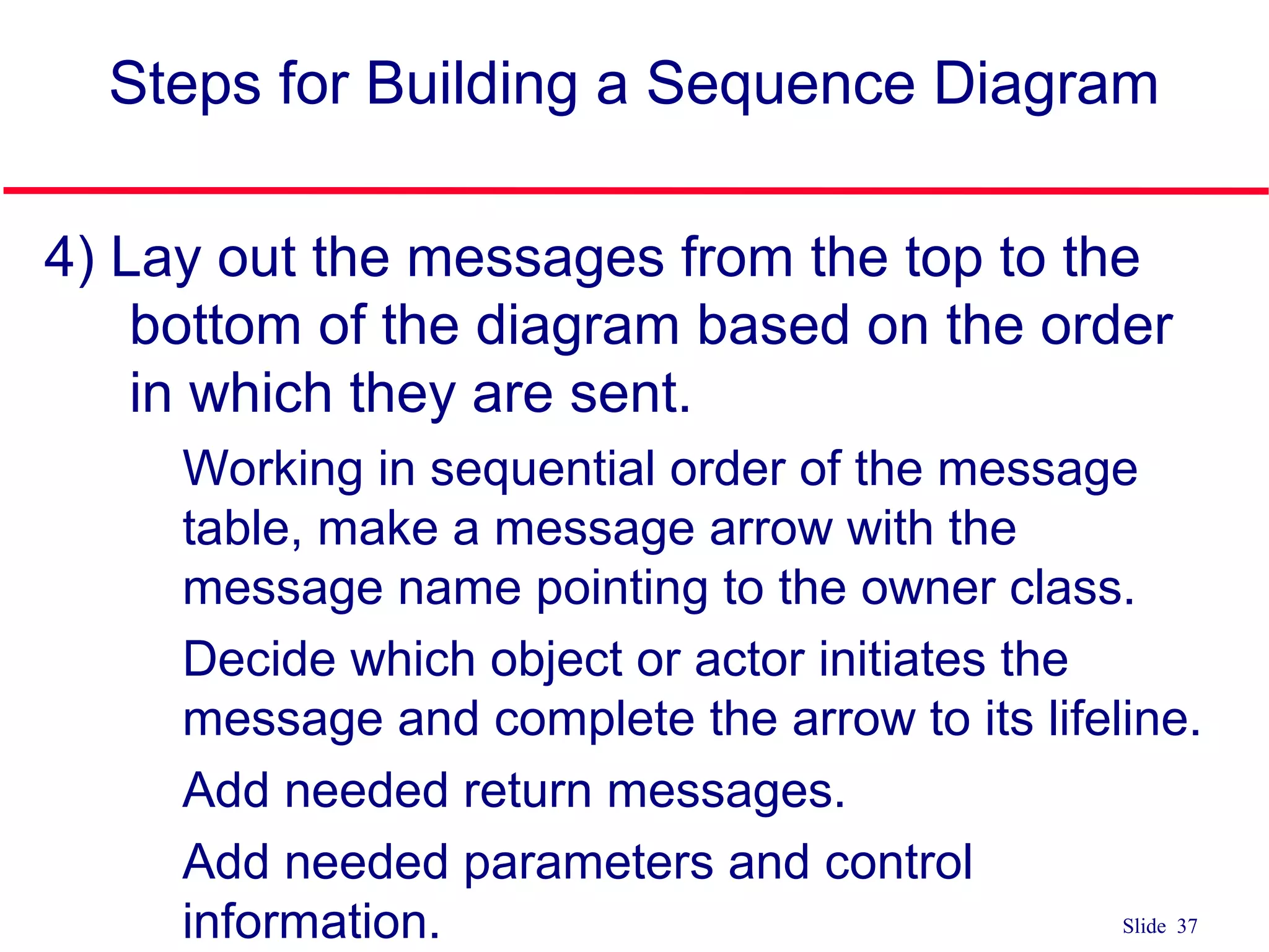
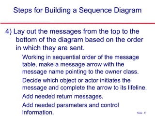
4) Layout the messages from the top to the
bottom of the diagram based on the order
in which they are sent.
a) Working in sequential order of the message
table, make a message arrow with the
message name pointing to the owner class.
b) Decide which object or actor initiates the
message and complete the arrow to its lifeline.
c) Add needed return messages.
d) Add needed parameters and control
information.
Steps for Building a Sequence Diagram
38.
Slide 38
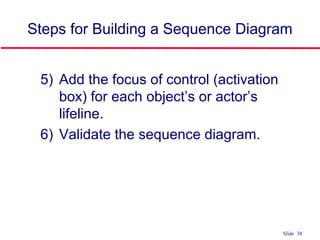
5) Addthe focus of control (activation
box) for each object’s or actor’s
lifeline.
6) Validate the sequence diagram.
Steps for Building a Sequence Diagram
#3 1) Sequence diagram
Emphasize explicit chronological sequence of messages
Useful in situations where the order in which events occurs is important
WE ARE BUILDING ONLY SEQUENCE DIAGRAMS; helpful in seeing if you have all the methods for the different classes
2) Collaboration diagrams
Emphasize the relationship between objects
Powerful tool for understanding the structure of the software product
Events are represented by annotated arrows placed alongside lines connecting boxes containing the names of actors
#4 1) Sequence diagram
Emphasize explicit chronological sequence of messages
Useful in situations where the order in which events occurs is important
WE ARE BUILDING ONLY SEQUENCE DIAGRAMS; helpful in seeing if you have all the methods for the different classes
2) Collaboration diagrams
Emphasize the relationship between objects
Powerful tool for understanding the structure of the software product
Events are represented by annotated arrows placed alongside lines connecting boxes containing the names of actors
#5 In 3350, each team MUST CREATE SEQUENCE DIAGRAM FOR NORMAL SCENARIO FOR EACH USE CASE ON USE CASE DIAGRAM
Sequence Diagram
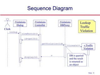
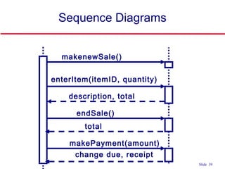
Used to document the details of a use case
Shows the sequence of messages that implement a service or transaction
Class diagram has a modeling focus on the class level while sequence diagram has a modeling focus is on the object level
Represents a scenario from a use case
Is a graphical representation of interactions between objects showing the sending and receiving of messages in sequence
Emphasize the time-based ordering of the activity that takes place among a set of objects
Used to understand the flow of control of a scenario by time
Depicts the objects and classes involved in the scenario and the sequence of messages exchanged between the objects needed to carry out the functionality of the scenario
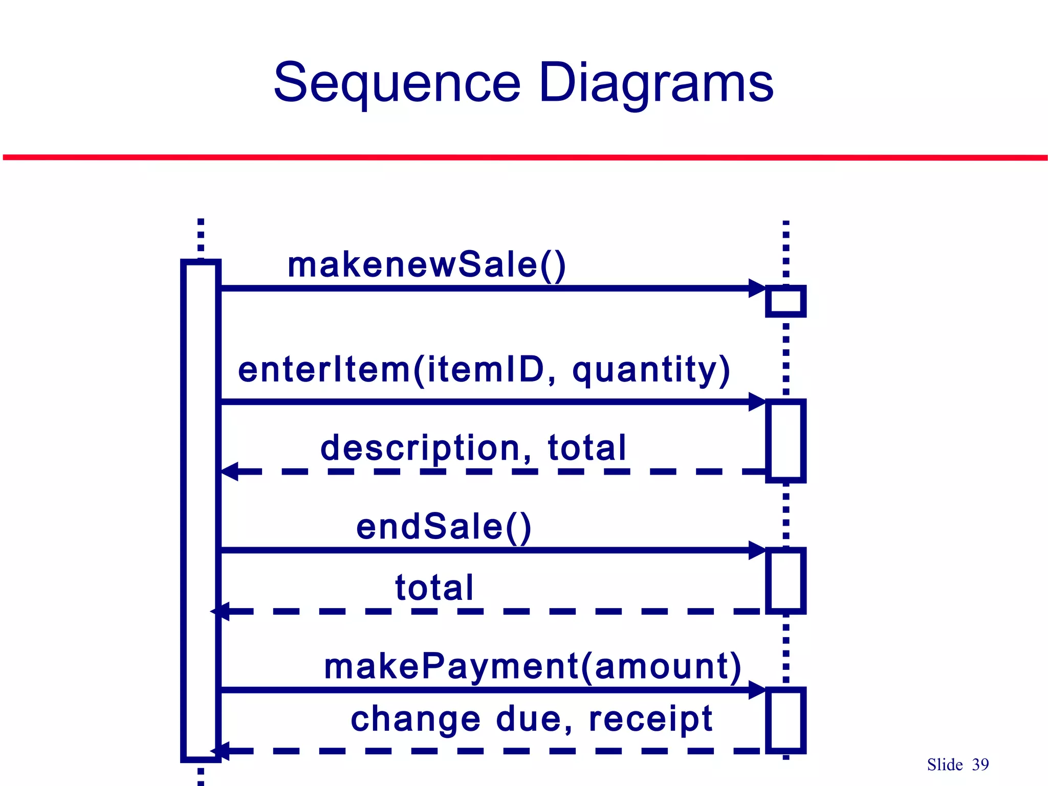
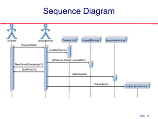
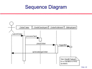
#6 In a sequence diagram
Each column represents an object that is participating in the interaction.
The vertical axis represents time (from top to bottom).
Messages are shown by full arrows.
Labels on full arrows represent message names and arguments.
The operation can itself send other requests to other objects
An object can request an operation from itself (looping arrow)
Activations
the time it takes to perform an operation
are depicted by a rectangle attached to an object.
The height of the rectangle is indicative for the duration of the operation
The vertical rectangle shows that an object is active, that is, it is handling a request made by another object.
#8 Sequence Diagram
Shows the sequence of messages that implement a service or transaction
Class diagram has a modeling focus on the class level while sequence diagram has a modeling focus is on the object level
Emphasize the time-based ordering of the activity that takes place among a set of objects
Used to understand the flow of control of a scenario by time
Depicts the objects and classes involved in the scenario and the sequence of messages exchanged between the objects needed to carry out the functionality of the scenario
#9 Object in a sequence diagram
Still represented by the rectangle with object name on inside
#10 3 ways to name:
Just an object name
Object name and class name
Just a class name
Object names are always underlined and begin with a lowercase letter
Class names are always capitalized
Naming objects
Name classes consistently with your class diagram (same classes).
Include instance names when objects are referred to in messages or when several objects of the same type exist in the diagram.
Most of the time you use the class name, but if you refer to a particular instance in a scenario the object:Class notation is used.
Objects can be named by
Using generic object names to clarify the class
Including the name of the class after the name of the object, separated by a colon
#11 Actor in a Sequence diagram
Still represented by the stick figure as on use case diagram
don’t have to place in any particular order across the top of the diagram but better to organize them in the order in which they participate in the sequence
Illustrating actors as active objects models how actors interact with the system and how the system interacts with the user
Actors can call objects and objects can notify actors
#13 Messages
An interaction between two objects is performed as a message sent from one object to another.
HOW ACTIVE OBJECTS COMMUNICATE WITH EACH OTHER IN A SEQUENCE DIAGRAM
Illustrate the flow between the objects, how they interact, and what conditions change the flow
#14 Time required by the receiver object to process the message is denoted by focus of control
#15 3) Flat
Use when we don’t care and don’t know if a message is synchronous or asynchronous
NOTICE THAT THE ARROW HEAD IS ONLY 2 LINES, NOT A FILLED-IN TRIANGLE
#16 Synchronize Messages
The object :A is in a hold pattern waiting for the response from the object :B
Indicates that flow is interrupted until the message has completed, and any messages that were sent from that message are completed as well.
Used for procedural system flow where one piece of functionality is executed before another
Modeled with a solid arrow head and line
#17 Asynchronous messages
Used when control flow does not need to be interrupted before completing
Can be used for modeling concurrent systems
Can:
Create a new thread (a new activation record)
Create a new object
Communicate with a thread that is already running
Active objects own an execution thread and can initiate control activity.
#19 In a sequence diagram
Each column represents an object that is participating in the interaction.
The vertical axis represents time (from top to bottom).
Messages are shown by full arrows.
Labels on full arrows represent message names and arguments.
The operation can itself send other requests to other objects
An object can request an operation from itself (looping arrow)
Activations
the time it takes to perform an operation
are depicted by a rectangle attached to an object.
The height of the rectangle is indicative for the duration of the operation
The vertical rectangle shows that an object is active, that is, it is handling a request made by another object.
#21 Lifeline in a sequence diagram
Represented by a vertical line for which our book uses a dotted (dashed) line or other people use a solid line
Sometimes an object creates a temporary object and in this case an X is placed at the end of the object’s lifeline to show that it is going out of existence (is destroyed)
Example: shopping cart object for a Web commerce application which is no long needed while the order is placed
If objects exist in the system after they are used in the sequence diagram, their lifeline continues to the bottom of the diagram
#22 A focus of control in a sequence diagram
Shows the period of time in which an object has a thread of control
#23 In a sequence diagram
Each column represents an object that is participating in the interaction.
The vertical axis represents time (from top to bottom).
Messages are shown by full arrows.
Labels on full arrows represent message names and arguments.
The operation can itself send other requests to other objects
An object can request an operation from itself (looping arrow)
Activations
the time it takes to perform an operation
are depicted by a rectangle attached to an object.
The height of the rectangle is indicative for the duration of the operation
The vertical rectangle shows that an object is active, that is, it is handling a request made by another object.
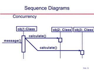
#24 Conditional messages: A message might contain a guard condition denoted in square brackets
#27 The branch represents concurrency if the guard conditions are mutually inclusive. Thus multiple messages are sent.
#31 People differ on how to different parts of the UML diagrams
In little UML book, Ambler (author) says that introducing object destruction often introduces clutter to the diagram
#33 Steps for building a sequence diagram
1) Set the context
Determine the context of the sequence diagram
Context of the diagram can be a system, a use case, a scenario of a use case, or an operation of a class
MOST COMMONLY, one use-case scenario
2) Identify which objects/actors will participate
Review the use case scenario and identify objects/actors
Objects are also found in the class diagrams
May uncover new classes/objects during this process
3) Set the lifeline
Draw vertical below each actor/object to represent its existence during the sequence
Place an X below an object at the point on the lifeline where the object goes out of existence
4) Lay out messages
Draw arrows to represent the messages being passed from object to object, with the arrow pointing in the message’s transmission direction
Review the use case scenario and look for communication between objects and actors OR objects and other objects
Identify senders and receivers of messages
Arrows should be placed in order from the first message (at the top) to the last (at the bottom) to show time sequence
Put name of operation to be invoked on top of arrow line (add arguments if known)
5) Add focus of control
Draw a narrow rectangular box over the top of the lifelines to represent when the actors or classes are sending and receiving messages
6) Validate
Guarantee that the diagram depicts all of the steps in the process
#34 Steps for building a sequence diagram
1) Set the context
Determine the context of the sequence diagram
Context of the diagram can be a system, a use case, a scenario of a use case, or an operation of a class
MOST COMMONLY, one use-case scenario
2) Identify which objects/actors will participate
Review the use case scenario and identify objects/actors
Objects are also found in the class diagrams
May uncover new classes/objects during this process
3) Set the lifeline
Draw vertical below each actor/object to represent its existence during the sequence
Place an X below an object at the point on the lifeline where the object goes out of existence
4) Lay out messages
Draw arrows to represent the messages being passed from object to object, with the arrow pointing in the message’s transmission direction
Review the use case scenario and look for communication between objects and actors OR objects and other objects
Identify senders and receivers of messages
Arrows should be placed in order from the first message (at the top) to the last (at the bottom) to show time sequence
Put name of operation to be invoked on top of arrow line (add arguments if known)
5) Add focus of control
Draw a narrow rectangular box over the top of the lifelines to represent when the actors or classes are sending and receiving messages
6) Validate
Guarantee that the diagram depicts all of the steps in the process
#35 Steps for building a sequence diagram
1) Set the context
Determine the context of the sequence diagram
Context of the diagram can be a system, a use case, a scenario of a use case, or an operation of a class
MOST COMMONLY, one use-case scenario
2) Identify which objects/actors will participate
Review the use case scenario and identify objects/actors
Objects are also found in the class diagrams
May uncover new classes/objects during this process
3) Set the lifeline
Draw vertical below each actor/object to represent its existence during the sequence
Place an X below an object at the point on the lifeline where the object goes out of existence
4) Lay out messages
Draw arrows to represent the messages being passed from object to object, with the arrow pointing in the message’s transmission direction
Review the use case scenario and look for communication between objects and actors OR objects and other objects
Identify senders and receivers of messages
Arrows should be placed in order from the first message (at the top) to the last (at the bottom) to show time sequence
Put name of operation to be invoked on top of arrow line (add arguments if known)
5) Add focus of control
Draw a narrow rectangular box over the top of the lifelines to represent when the actors or classes are sending and receiving messages
6) Validate
Guarantee that the diagram depicts all of the steps in the process
#36 Steps for building a sequence diagram
1) Set the context
Determine the context of the sequence diagram
Context of the diagram can be a system, a use case, a scenario of a use case, or an operation of a class
MOST COMMONLY, one use-case scenario
2) Identify which objects/actors will participate
Review the use case scenario and identify objects/actors
Objects are also found in the class diagrams
May uncover new classes/objects during this process
3) Set the lifeline
Draw vertical below each actor/object to represent its existence during the sequence
Place an X below an object at the point on the lifeline where the object goes out of existence
4) Lay out messages
Draw arrows to represent the messages being passed from object to object, with the arrow pointing in the message’s transmission direction
Review the use case scenario and look for communication between objects and actors OR objects and other objects
Identify senders and receivers of messages
Arrows should be placed in order from the first message (at the top) to the last (at the bottom) to show time sequence
Put name of operation to be invoked on top of arrow line (add arguments if known)
5) Add focus of control
Draw a narrow rectangular box over the top of the lifelines to represent when the actors or classes are sending and receiving messages
6) Validate
Guarantee that the diagram depicts all of the steps in the process
#37 Steps for building a sequence diagram
1) Set the context
Determine the context of the sequence diagram
Context of the diagram can be a system, a use case, a scenario of a use case, or an operation of a class
MOST COMMONLY, one use-case scenario
2) Identify which objects/actors will participate
Review the use case scenario and identify objects/actors
Objects are also found in the class diagrams
May uncover new classes/objects during this process
3) Set the lifeline
Draw vertical below each actor/object to represent its existence during the sequence
Place an X below an object at the point on the lifeline where the object goes out of existence
4) Lay out messages
Draw arrows to represent the messages being passed from object to object, with the arrow pointing in the message’s transmission direction
Review the use case scenario and look for communication between objects and actors OR objects and other objects
Identify senders and receivers of messages
Arrows should be placed in order from the first message (at the top) to the last (at the bottom) to show time sequence
Put name of operation to be invoked on top of arrow line (add arguments if known)
5) Add focus of control
Draw a narrow rectangular box over the top of the lifelines to represent when the actors or classes are sending and receiving messages
6) Validate
Guarantee that the diagram depicts all of the steps in the process
#38 Steps for building a sequence diagram
1) Set the context
Determine the context of the sequence diagram
Context of the diagram can be a system, a use case, a scenario of a use case, or an operation of a class
MOST COMMONLY, one use-case scenario
2) Identify which objects/actors will participate
Review the use case scenario and identify objects/actors
Objects are also found in the class diagrams
May uncover new classes/objects during this process
3) Set the lifeline
Draw vertical below each actor/object to represent its existence during the sequence
Place an X below an object at the point on the lifeline where the object goes out of existence
4) Lay out messages
Draw arrows to represent the messages being passed from object to object, with the arrow pointing in the message’s transmission direction
Review the use case scenario and look for communication between objects and actors OR objects and other objects
Identify senders and receivers of messages
Arrows should be placed in order from the first message (at the top) to the last (at the bottom) to show time sequence
Put name of operation to be invoked on top of arrow line (add arguments if known)
5) Add focus of control
Draw a narrow rectangular box over the top of the lifelines to represent when the actors or classes are sending and receiving messages
6) Validate
Guarantee that the diagram depicts all of the steps in the process
#39 Steps for building a sequence diagram
1) Set the context
Determine the context of the sequence diagram
Context of the diagram can be a system, a use case, a scenario of a use case, or an operation of a class
MOST COMMONLY, one use-case scenario
2) Identify which objects/actors will participate
Review the use case scenario and identify objects/actors
Objects are also found in the class diagrams
May uncover new classes/objects during this process
3) Set the lifeline
Draw vertical below each actor/object to represent its existence during the sequence
Place an X below an object at the point on the lifeline where the object goes out of existence
4) Lay out messages
Draw arrows to represent the messages being passed from object to object, with the arrow pointing in the message’s transmission direction
Review the use case scenario and look for communication between objects and actors OR objects and other objects
Identify senders and receivers of messages
Arrows should be placed in order from the first message (at the top) to the last (at the bottom) to show time sequence
Put name of operation to be invoked on top of arrow line (add arguments if known)
5) Add focus of control
Draw a narrow rectangular box over the top of the lifelines to represent when the actors or classes are sending and receiving messages
6) Validate
Guarantee that the diagram depicts all of the steps in the process
#42 Steps for building a sequence diagram
1) Set the context
Determine the context of the sequence diagram
Context of the diagram can be a system, a use case, a scenario of a use case, or an operation of a class
MOST COMMONLY, one use-case scenario
2) Identify which objects/actors will participate
Review the use case scenario and identify objects/actors
Objects are also found in the class diagrams
May uncover new classes/objects during this process
3) Set the lifeline
Draw vertical below each actor/object to represent its existence during the sequence
Place an X below an object at the point on the lifeline where the object goes out of existence
4) Lay out messages
Draw arrows to represent the messages being passed from object to object, with the arrow pointing in the message’s transmission direction
Review the use case scenario and look for communication between objects and actors OR objects and other objects
Identify senders and receivers of messages
Arrows should be placed in order from the first message (at the top) to the last (at the bottom) to show time sequence
Put name of operation to be invoked on top of arrow line (add arguments if known)
5) Add focus of control
Draw a narrow rectangular box over the top of the lifelines to represent when the actors or classes are sending and receiving messages
6) Validate
Guarantee that the diagram depicts all of the steps in the process

![Slide 5
Sequence Diagram
member:
LibraryMember
book:Book
:Book
Copy
borrow(book)
ok = mayBorrow()
[ok] borrow(member)
setTaken(member)
X-Axis (objects)
Y-Axis(time)
ObjectLife
Line
Message
Focus of
control
Condition](https://image.slidesharecdn.com/lecture11usecasesequencediagram-180413173952/85/Lecture11-use-case-sequence-diagram-5-320.jpg)

![Slide 9
Active Objects
Object
• Can be any object or class that is
valid within the system
• Object naming
• Syntax
[instanceName][:className]
1. Class name only :Classname
2. Instance name only objectName
3. Instance name and class name
together object:Class
myBirthdy
:Date](https://image.slidesharecdn.com/lecture11usecasesequencediagram-180413173952/85/Lecture11-use-case-sequence-diagram-9-320.jpg)

![Slide 18
Sequence Diagram
member:
LibraryMember
book:Book
:Book
Copy
borrow(book)
ok = mayBorrow()
[ok] borrow(member)
setTaken(member)
X-Axis (objects)
Y-Axis(time)
ObjectLife
Line
Message
Focus of
control
Condition](https://image.slidesharecdn.com/lecture11usecasesequencediagram-180413173952/85/Lecture11-use-case-sequence-diagram-18-320.jpg)
![Slide 22
Sequence Diagram
member:
LibraryMember
book:Book
:Book
Copy
borrow(book)
ok = mayBorrow()
[ok] borrow(member)
setTaken(member)
X-Axis (objects)
Y-Axis(time)
ObjectLife
Line
Message
Focus of
control
Condition](https://image.slidesharecdn.com/lecture11usecasesequencediagram-180413173952/85/Lecture11-use-case-sequence-diagram-22-320.jpg)
![Slide 23
Control Information
Condition
syntax: ‘[‘ expression ’]’ message-label
The message is sent only if the
condition is true
[ok] borrow(member)](https://image.slidesharecdn.com/lecture11usecasesequencediagram-180413173952/85/Lecture11-use-case-sequence-diagram-23-320.jpg)
![Slide 24
Elements of Sequence Diagram
obj1:Class
[x < 15] calculate()
obj2: Class
message()](https://image.slidesharecdn.com/lecture11usecasesequencediagram-180413173952/85/Lecture11-use-case-sequence-diagram-24-320.jpg)
![Slide 25
Sequence Diagrams
obj1:Class
[x < 15] calculate()
obj2: Class
message()
obj3: Class
[x > 20] calculate()](https://image.slidesharecdn.com/lecture11usecasesequencediagram-180413173952/85/Lecture11-use-case-sequence-diagram-25-320.jpg)
![Slide 28
Control Information
Iteration
syntax: * [ ‘[‘ expression ‘]’ ]
message-label
The message is sent many times to
possibly multiple receiver objects.
*draw()](https://image.slidesharecdn.com/lecture11usecasesequencediagram-180413173952/85/Lecture11-use-case-sequence-diagram-28-320.jpg)
![Slide 29
Control Information
Iteration example
:Driver
*[until full] insert()
:Bus:CompoundShape :Shape
*draw()
draw()](https://image.slidesharecdn.com/lecture11usecasesequencediagram-180413173952/85/Lecture11-use-case-sequence-diagram-29-320.jpg)


![Slide 5
Sequence Diagram
member:
LibraryMember
book:Book
:Book
Copy
borrow(book)
ok = mayBorrow()
[ok] borrow(member)
setTaken(member)
X-Axis (objects)
Y-Axis(time)
ObjectLife
Line
Message
Focus of
control
Condition](https://image.slidesharecdn.com/lecture11usecasesequencediagram-180413173952/75/Lecture11-use-case-sequence-diagram-5-2048.jpg)
![Slide 9
Active Objects
Object
• Can be any object or class that is
valid within the system
• Object naming
• Syntax
[instanceName][:className]
1. Class name only :Classname
2. Instance name only objectName
3. Instance name and class name
together object:Class
myBirthdy
:Date](https://image.slidesharecdn.com/lecture11usecasesequencediagram-180413173952/75/Lecture11-use-case-sequence-diagram-9-2048.jpg)
![Slide 18
Sequence Diagram
member:
LibraryMember
book:Book
:Book
Copy
borrow(book)
ok = mayBorrow()
[ok] borrow(member)
setTaken(member)
X-Axis (objects)
Y-Axis(time)
ObjectLife
Line
Message
Focus of
control
Condition](https://image.slidesharecdn.com/lecture11usecasesequencediagram-180413173952/75/Lecture11-use-case-sequence-diagram-18-2048.jpg)
![Slide 22
Sequence Diagram
member:
LibraryMember
book:Book
:Book
Copy
borrow(book)
ok = mayBorrow()
[ok] borrow(member)
setTaken(member)
X-Axis (objects)
Y-Axis(time)
ObjectLife
Line
Message
Focus of
control
Condition](https://image.slidesharecdn.com/lecture11usecasesequencediagram-180413173952/75/Lecture11-use-case-sequence-diagram-22-2048.jpg)
![Slide 23
Control Information
Condition
syntax: ‘[‘ expression ’]’ message-label
The message is sent only if the
condition is true
[ok] borrow(member)](https://image.slidesharecdn.com/lecture11usecasesequencediagram-180413173952/75/Lecture11-use-case-sequence-diagram-23-2048.jpg)
![Slide 24
Elements of Sequence Diagram
obj1:Class
[x < 15] calculate()
obj2: Class
message()](https://image.slidesharecdn.com/lecture11usecasesequencediagram-180413173952/75/Lecture11-use-case-sequence-diagram-24-2048.jpg)
![Slide 25
Sequence Diagrams
obj1:Class
[x < 15] calculate()
obj2: Class
message()
obj3: Class
[x > 20] calculate()](https://image.slidesharecdn.com/lecture11usecasesequencediagram-180413173952/75/Lecture11-use-case-sequence-diagram-25-2048.jpg)

![Slide 28
Control Information
Iteration
syntax: * [ ‘[‘ expression ‘]’ ]
message-label
The message is sent many times to
possibly multiple receiver objects.
*draw()](https://image.slidesharecdn.com/lecture11usecasesequencediagram-180413173952/75/Lecture11-use-case-sequence-diagram-28-2048.jpg)
![Slide 29
Control Information
Iteration example
:Driver
*[until full] insert()
:Bus:CompoundShape :Shape
*draw()
draw()](https://image.slidesharecdn.com/lecture11usecasesequencediagram-180413173952/75/Lecture11-use-case-sequence-diagram-29-2048.jpg)