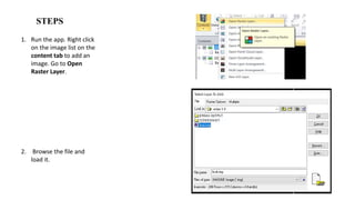
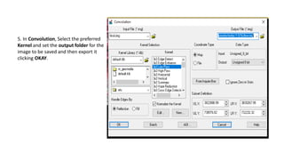
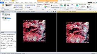
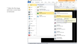
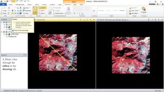
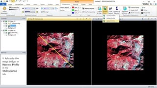
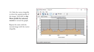
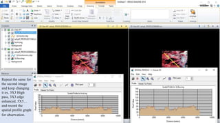
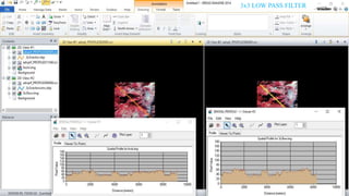
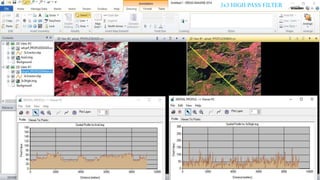
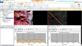
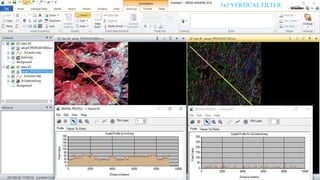
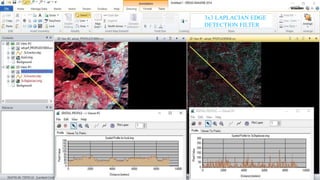
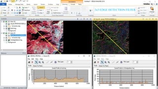
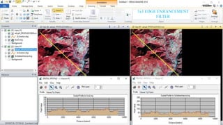
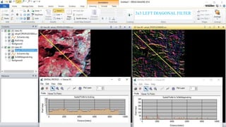
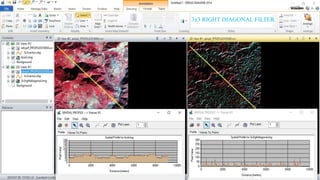
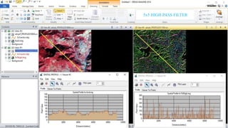
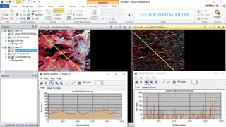
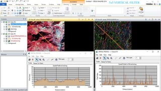
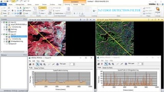
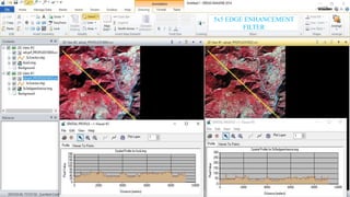
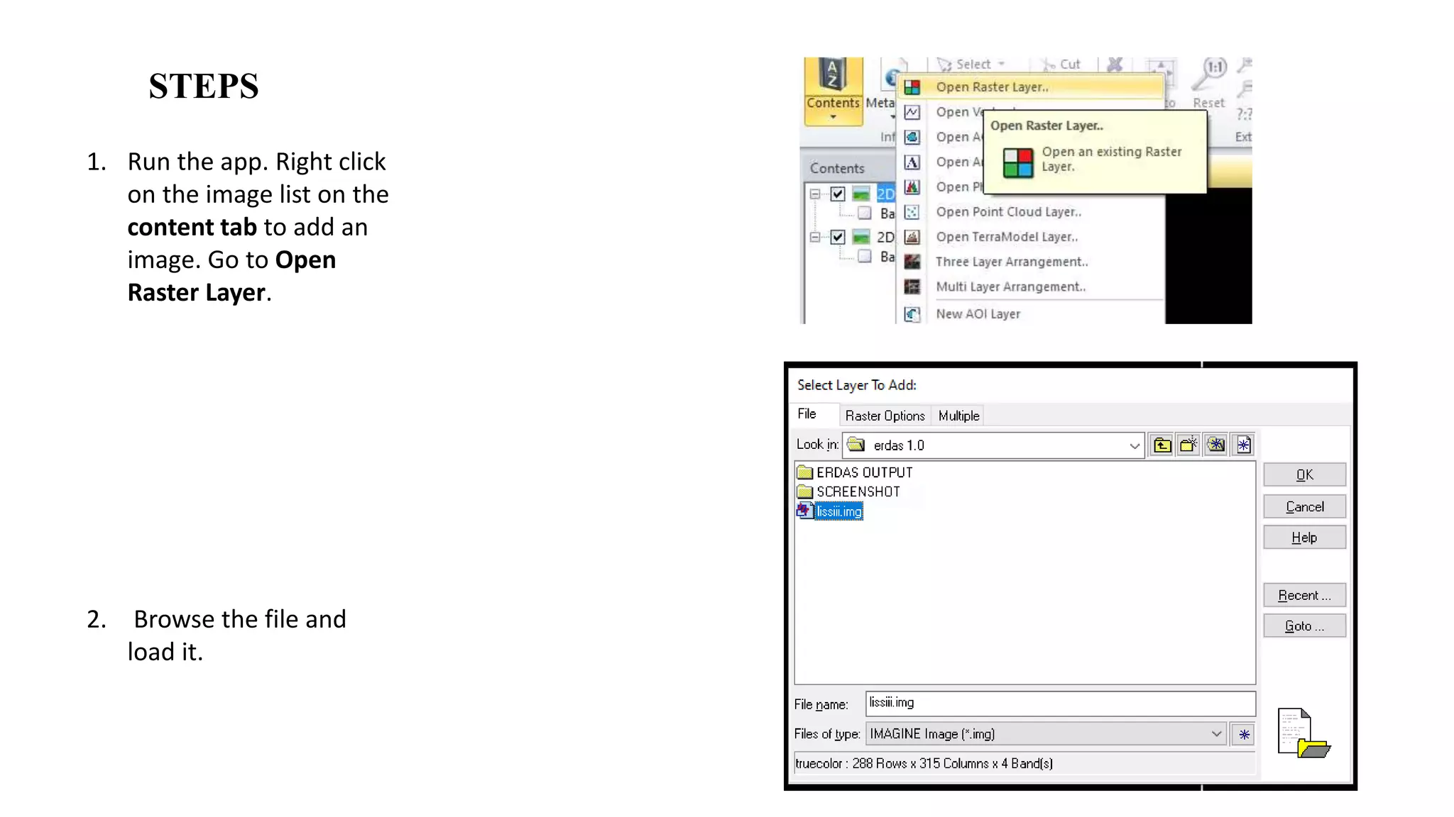
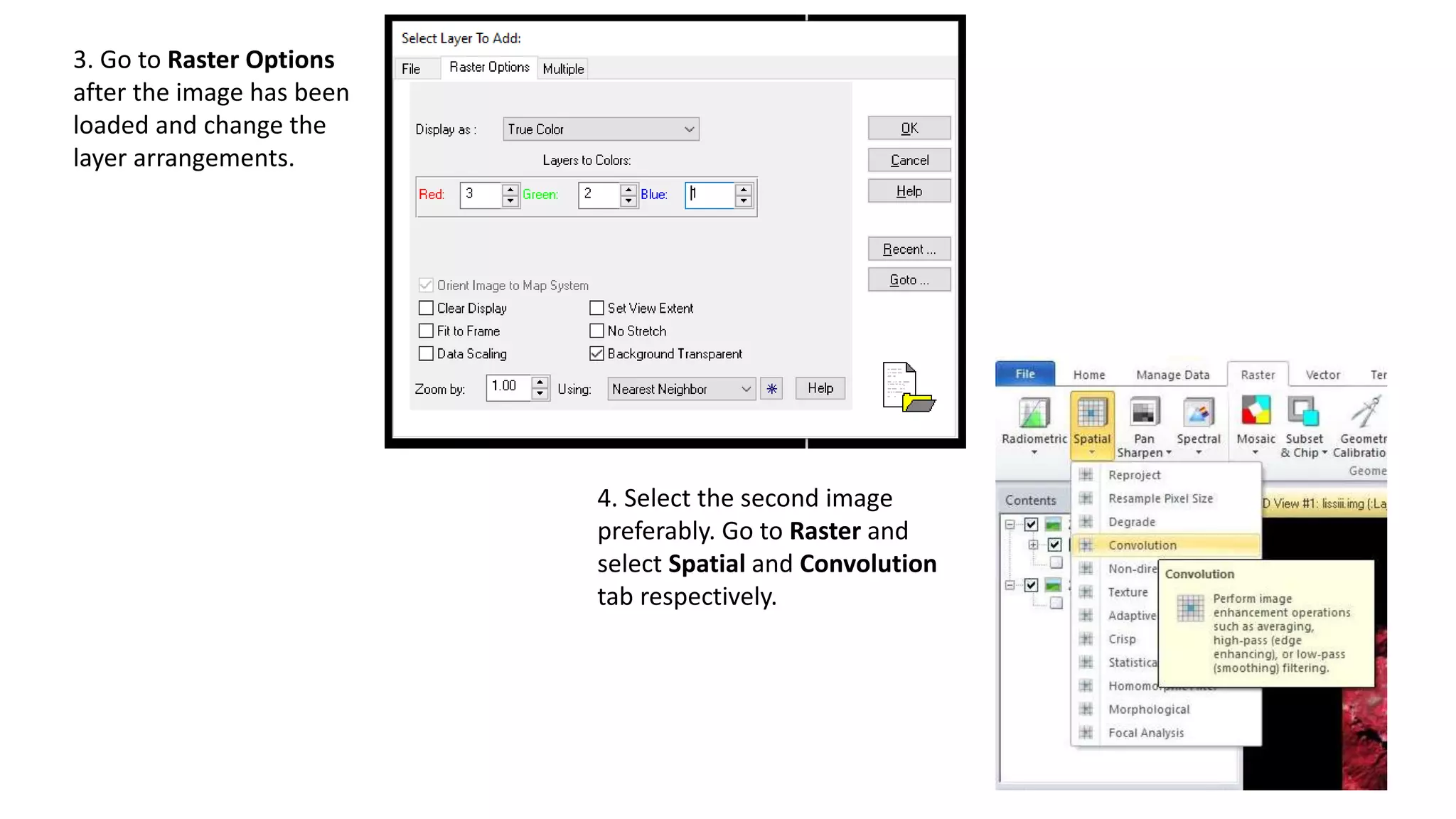
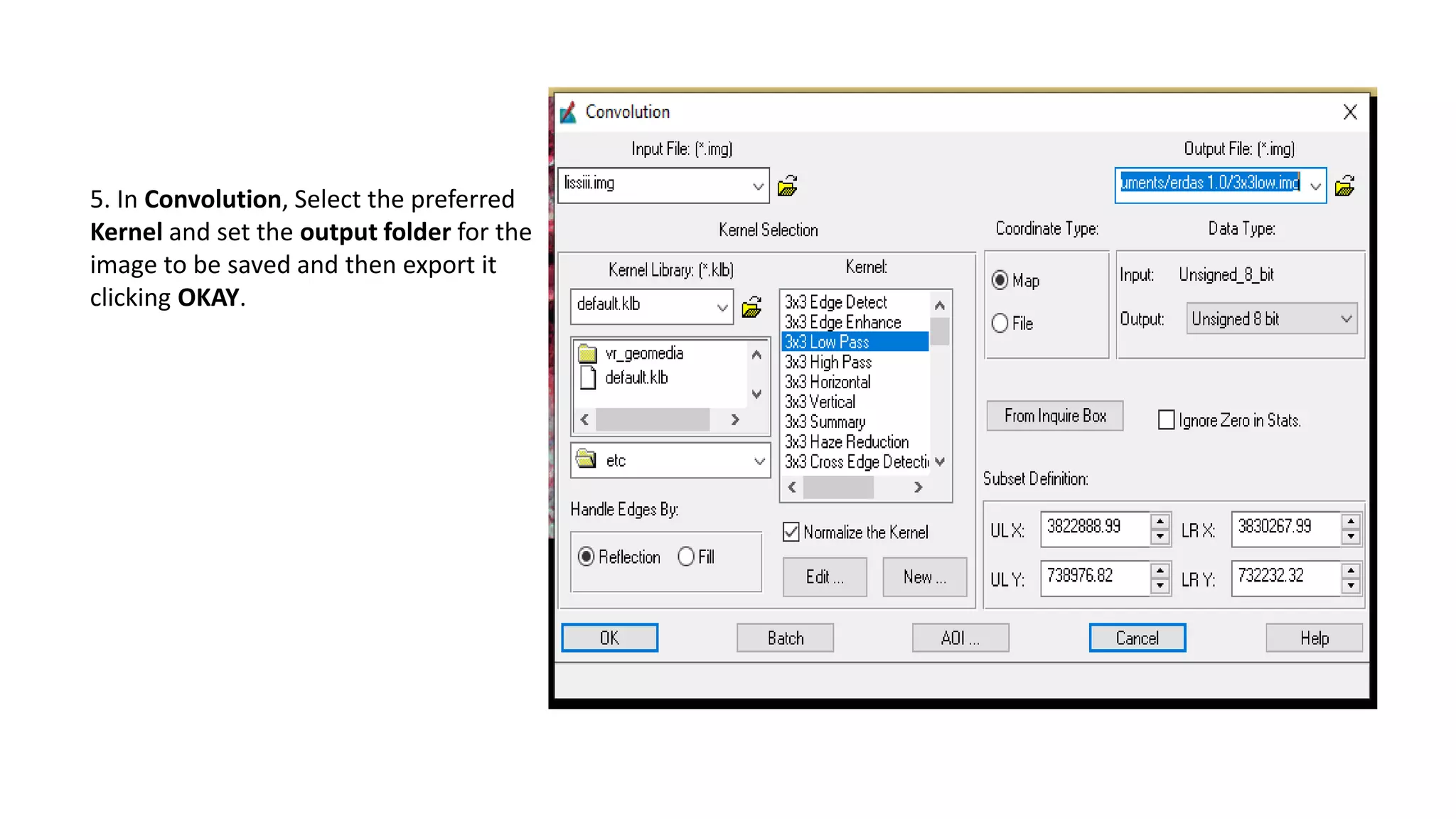
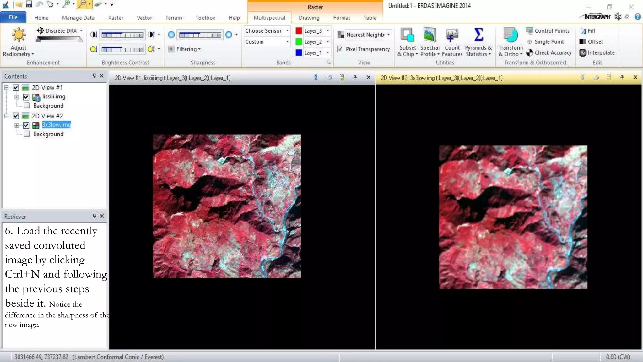
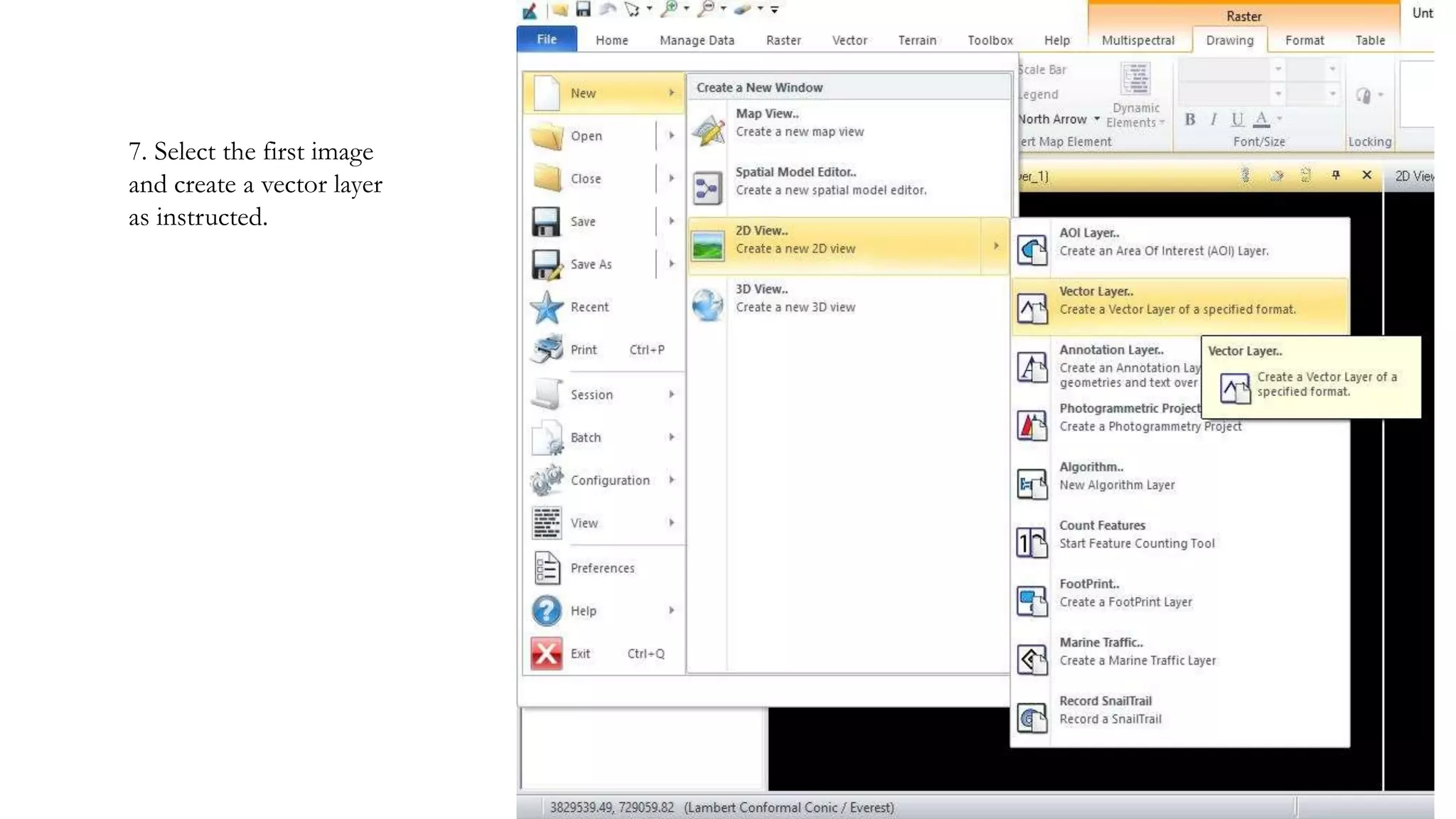
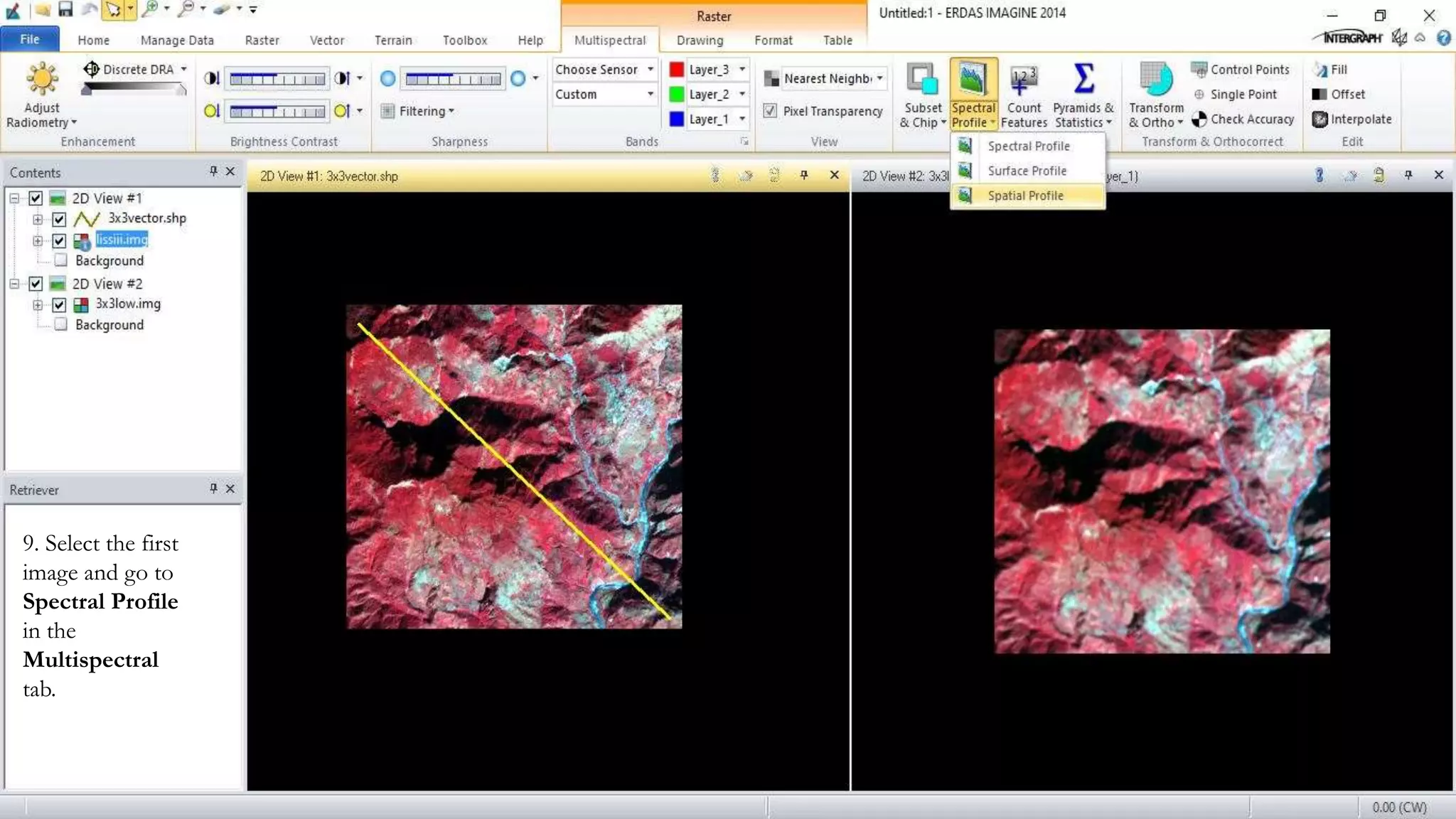
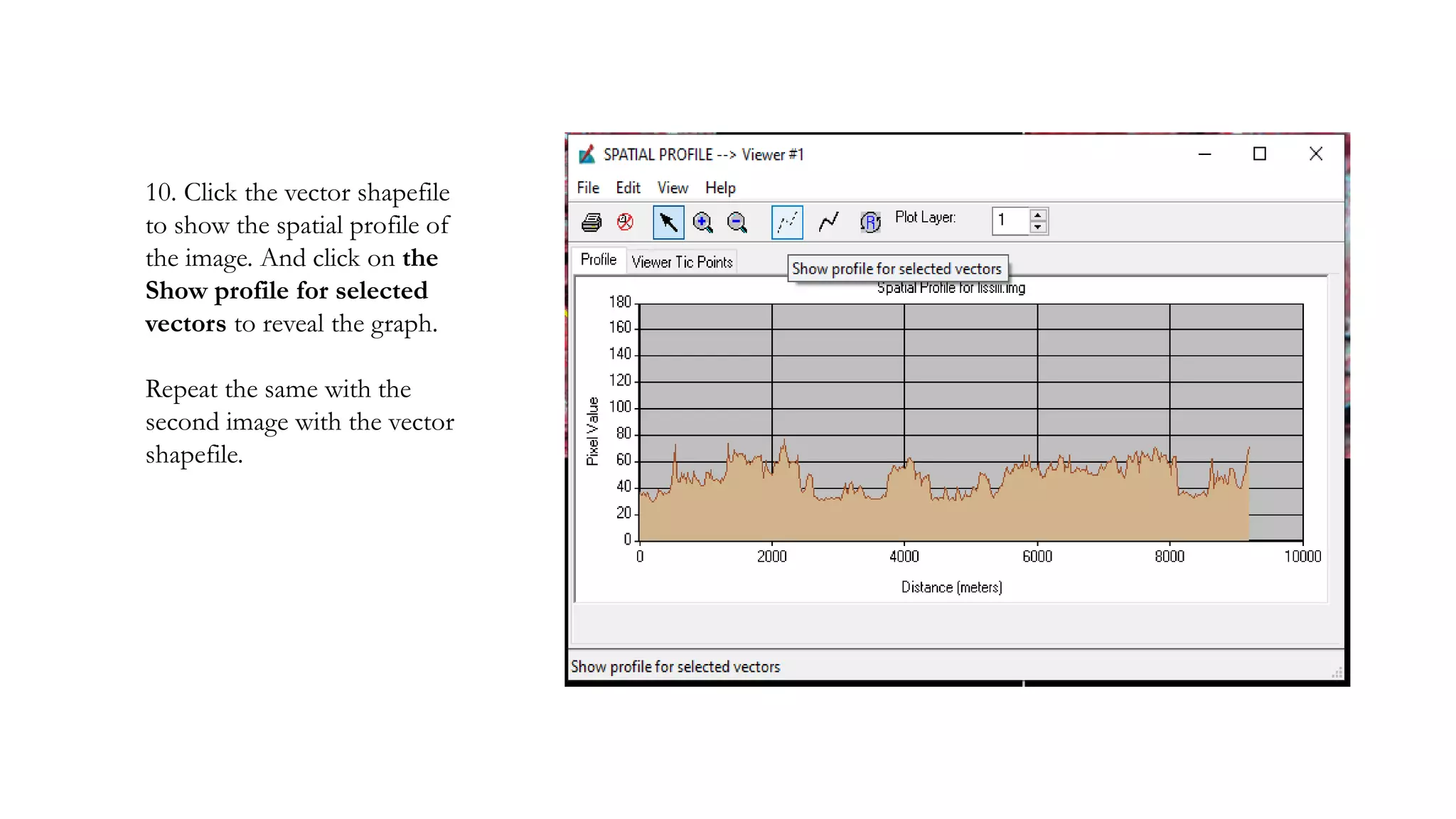
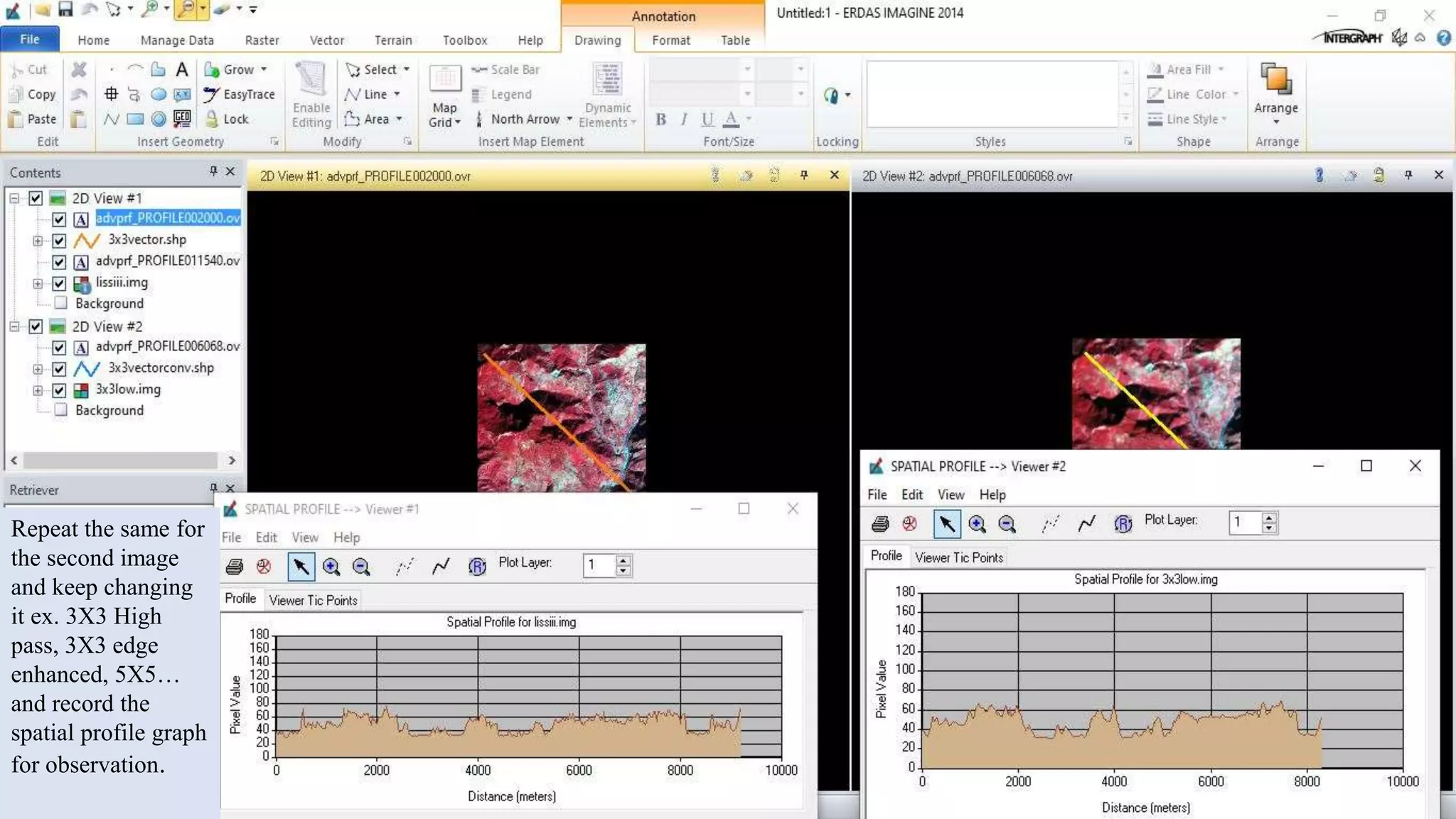
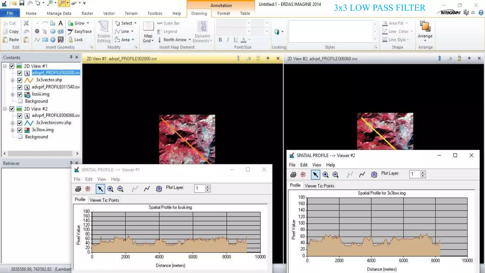
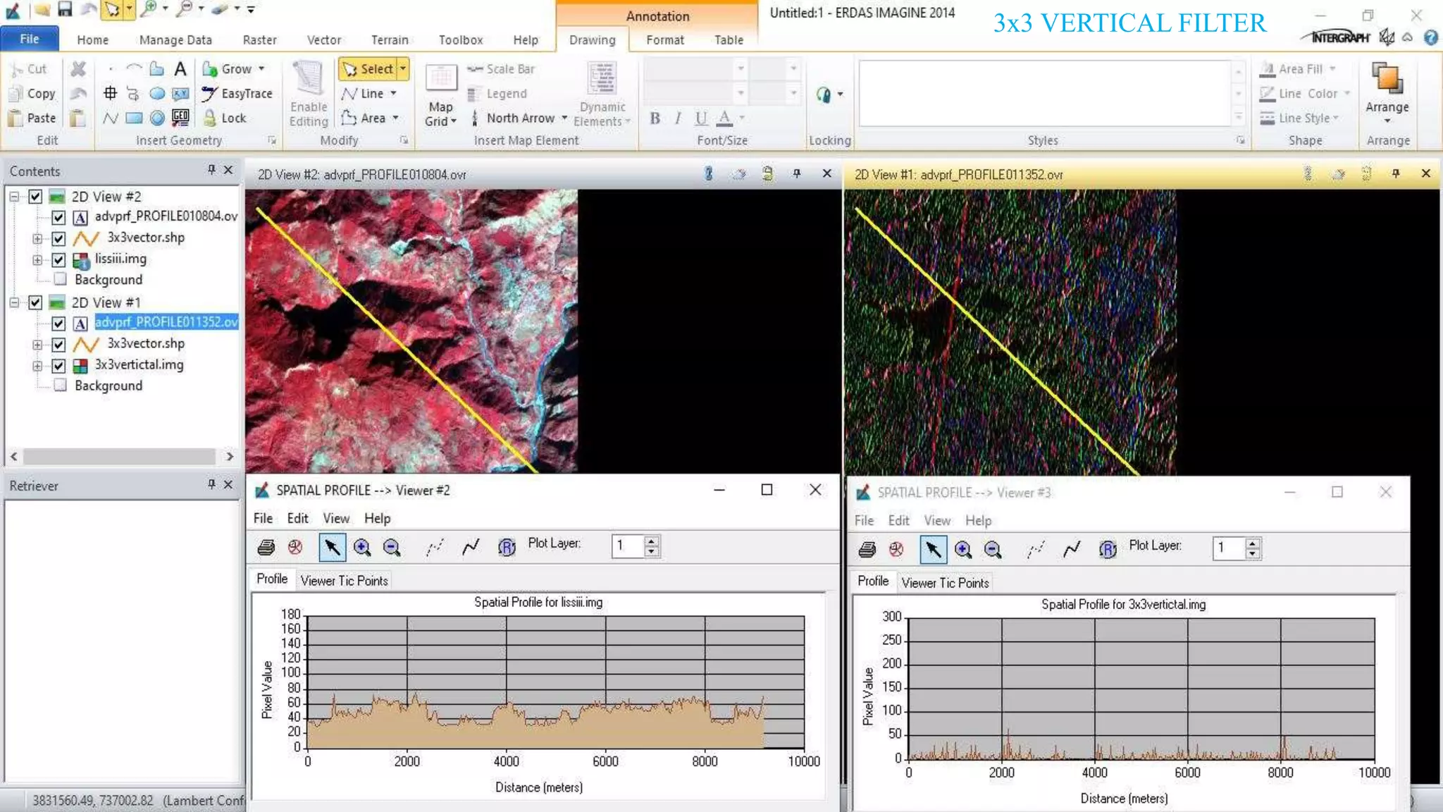
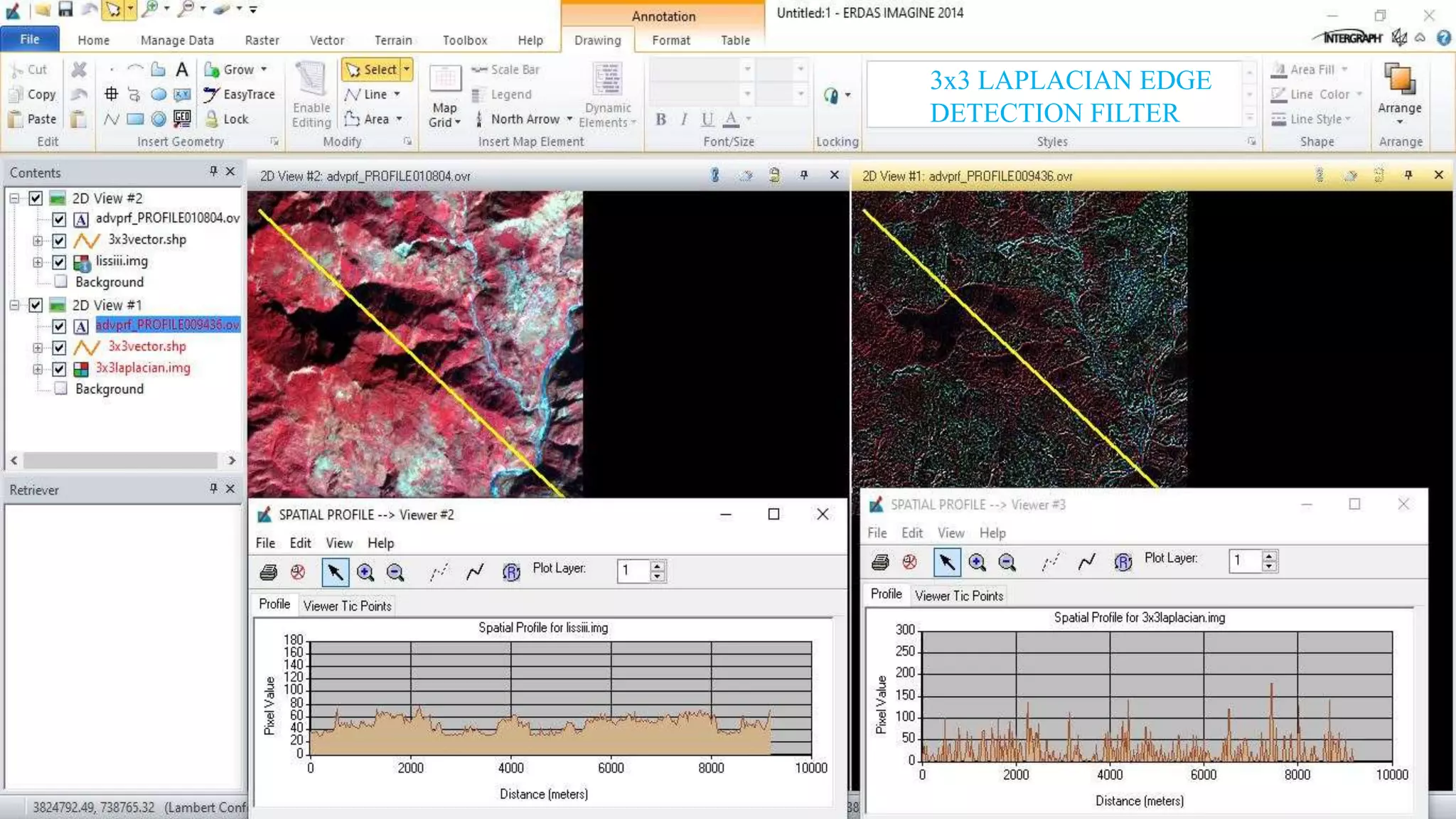
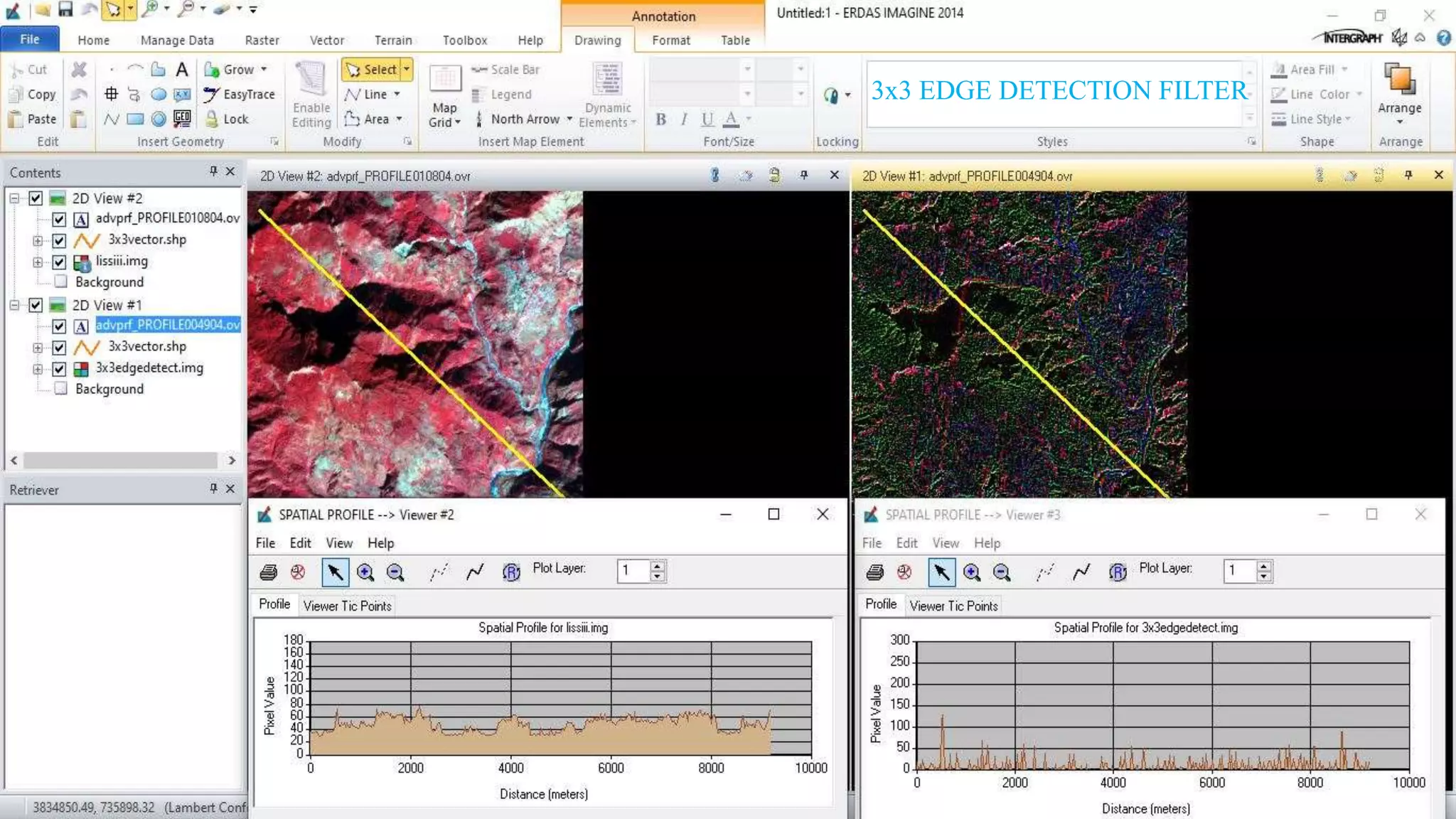
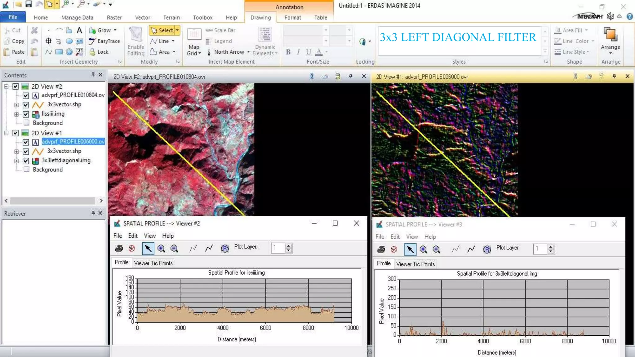
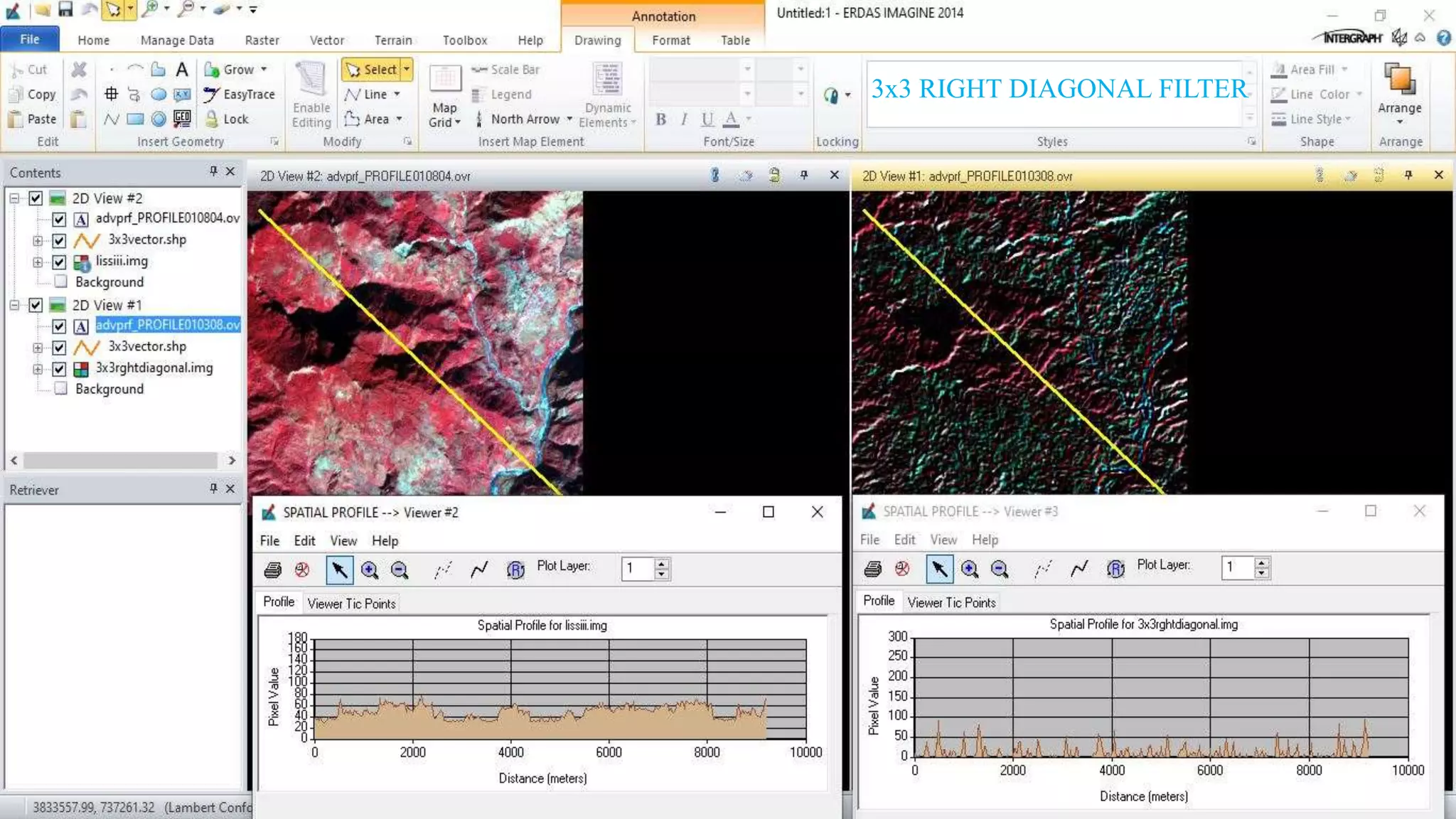
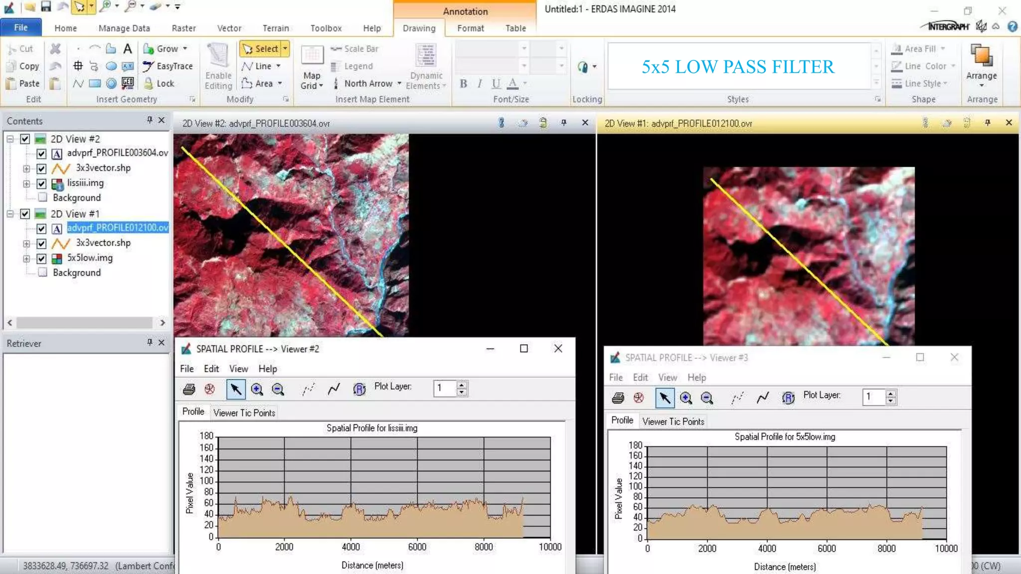
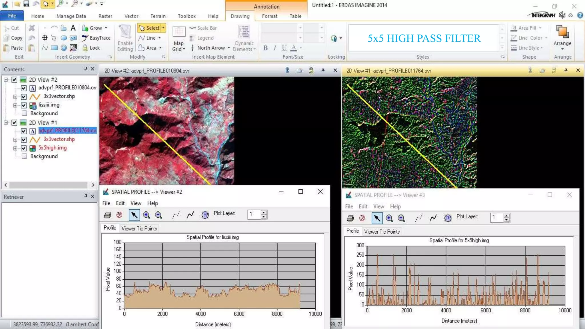
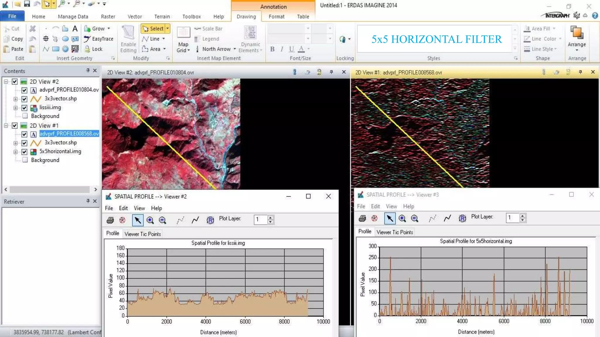
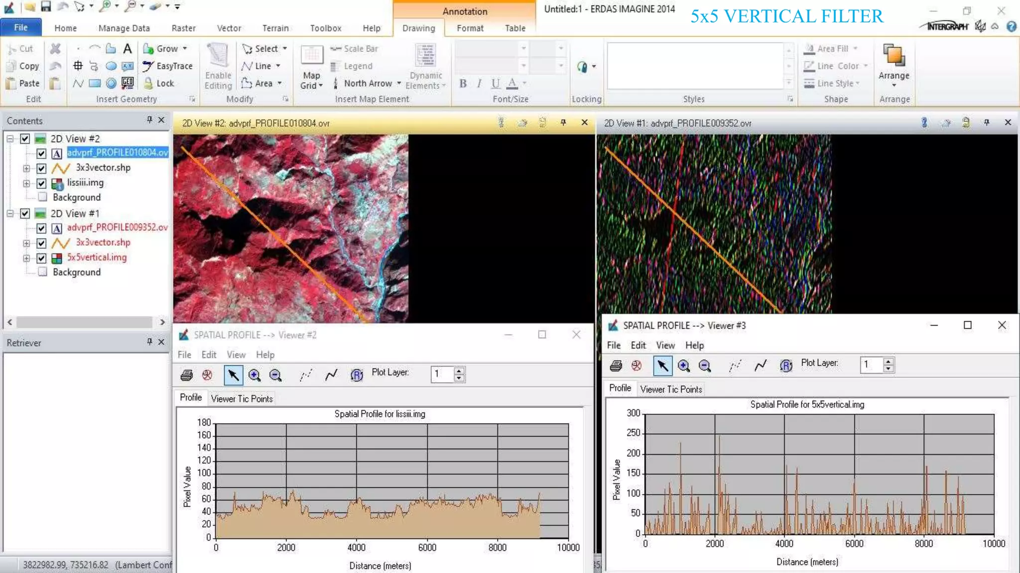
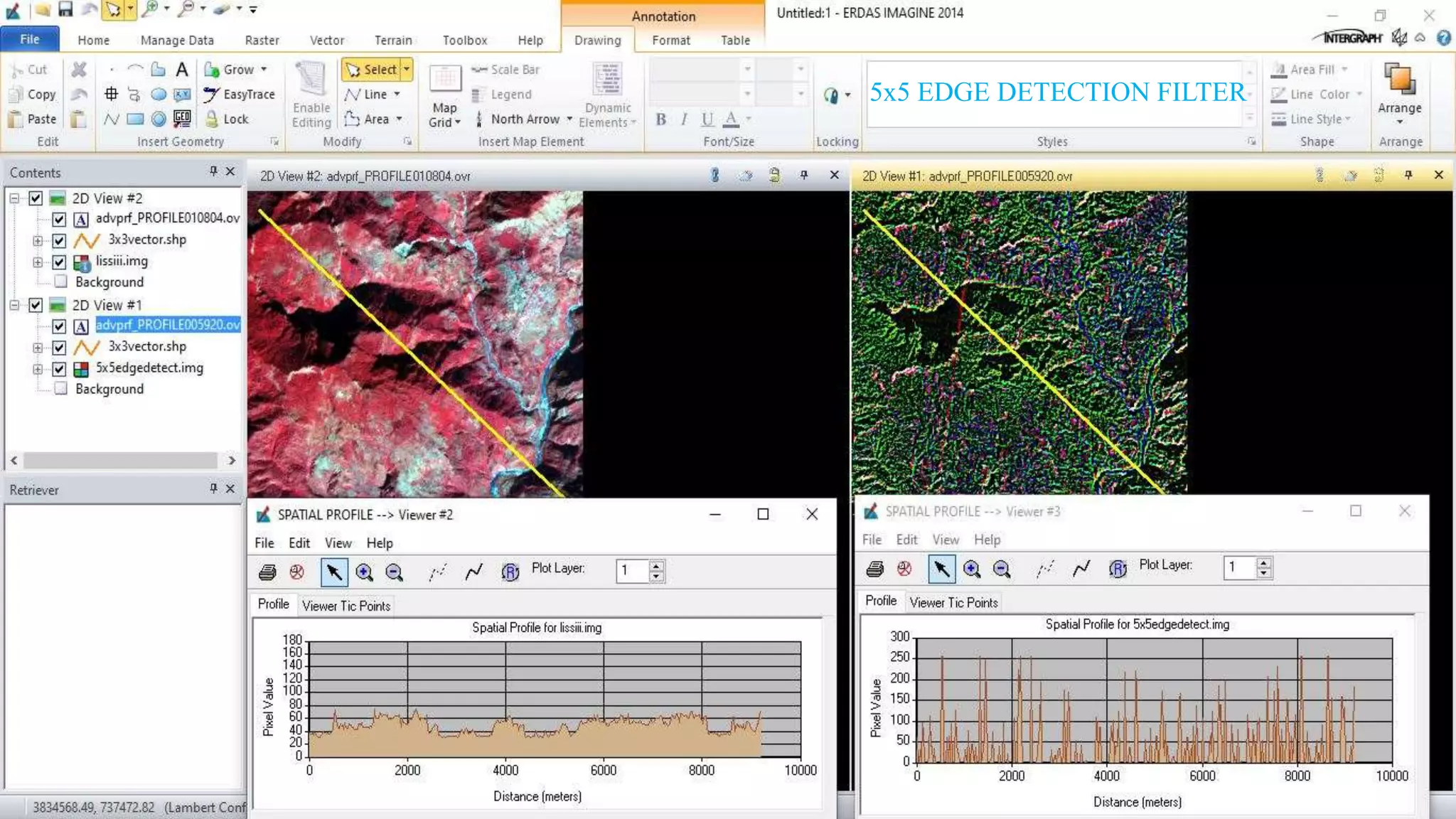
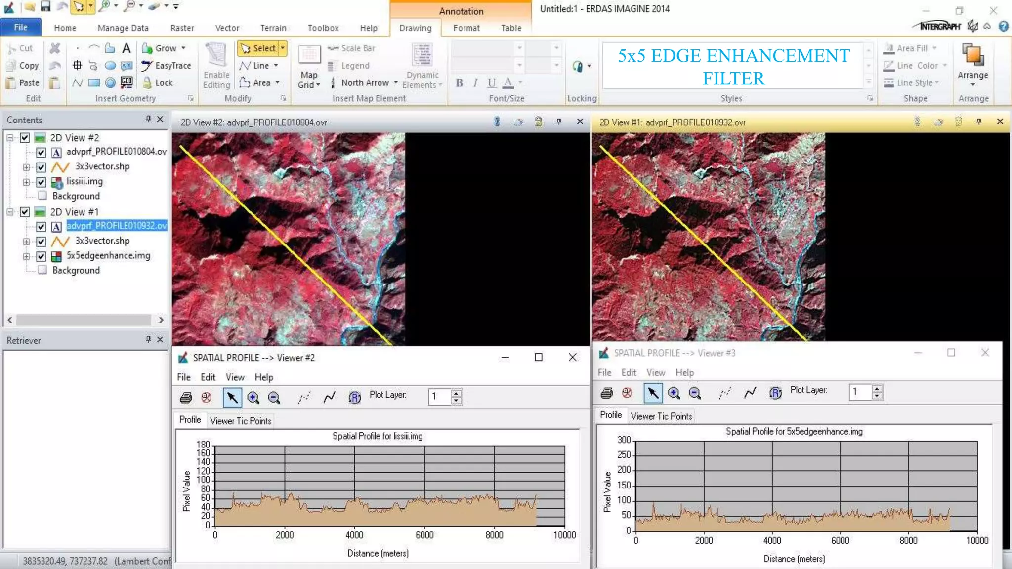
KEMBAR78
Remote Sensing:. Image Filtering | PPTX
IMAGE
FILTERING
KAMLESH KUMAR
The advantage of digital imagery is that it allows us to manipulate the digital pixel values in the image. Even after
the radiometric corrections image may still not be optimized for visual interpretation. An image 'enhancement' is
basically anything that makes it easier or better to visually interpret. An enhancement is performed for a specific
application as well. This enhancement may be inappropriate for another purpose, which would demand a different
type of enhancement.
Filtering is used to enhance the appearance of an image. Spatial filters are designed to highlight or suppress
specific features in an image based on their spatial frequency. ‘Rough’ textured areas of an image, where the
changes in tone are abrupt, have high spatial frequencies, while ‘smooth’ areas with little variation have low spatial
frequencies. A common filtering procedure involves moving a ‘matrix' of a few pixels in dimension (ie. 3x3, 5x5,
etc.) over each pixel in the image, using mathematical calculation and replacing the central pixel with the new
value.
A low-pass filter is designed to emphasize larger, homogeneous areas of similar tone and reduce the smaller detail
in an image. Thus, low-pass filters generally serve to smooth the appearance of an image. In some cases, like 'low-
pass filtering', the enhanced image can actually look worse than the original, but such an enhancement was likely
performed to help the interpreter see low spatial frequency features among the usual high frequency clutter found in
an image. High-pass filters do the opposite and serve to sharpen the appearance of fine detail in an
image. Directional, or edge detection filters are designed to highlight linear features, such as roads or field
boundaries. These filters can also be designed to enhance features which are oriented in specific directions.
1. Run the app. Right click
on the image list on the
content tab to add an
image. Go to Open
Raster Layer.
2. Browse the file and
load it.
STEPS
3. Go to Raster Options
after the image has been
loaded and change the
layer arrangements.
4. Select the second image
preferably. Go to Raster and
select Spatial and Convolution
tab respectively.
5. In Convolution, Select the preferred
Kernel and set the output folder for the
image to be saved and then export it
clicking OKAY.
6. Load the recently
saved convoluted
image by clicking
Ctrl+N and following
the previous steps
beside it. Notice the
difference in the sharpness of the
new image.
6. Go to the Raster tab and
7. Select the first image
and create a vector layer
as instructed.
8. Draw a line
through the
editor in the
drawing tab.
9. Select the first
image and go to
Spectral Profile
in the
Multispectral
tab.
10. Click the vector shapefile
to show the spatial profile of
the image. And click on the
Show profile for selected
vectors to reveal the graph.
Repeat the same with the
second image with the vector
shapefile.
Repeat the same for
the second image
and keep changing
it ex. 3X3 High
pass, 3X3 edge
enhanced, 5X5…
and record the
spatial profile graph
for observation.
IMAGE FILTRATION
SAMPLES
3x3 LOW PASS FILTER
3x3 HIGH PASS FILTER
3x3 HORIZONTAL FILTER
3x3 VERTICAL FILTER
3x3 LAPLACIAN EDGE
DETECTION FILTER
3x3 EDGE DETECTION FILTER
3x3 EDGE ENHANCEMENT
FILTER
3x3 LEFT DIAGONAL FILTER
3x3 RIGHT DIAGONAL FILTER
5x5 LOW PASS FILTER
5x5 HIGH PASS FILTER
5x5 HORIZONTAL FILTER
5x5 VERTICAL FILTER
5x5 EDGE DETECTION FILTER
5x5 EDGE ENHANCEMENT
FILTER
Signing off..

Remote Sensing:. Image Filtering

  • 1.
  • 2.
    The advantage ofdigital imagery is that it allows us to manipulate the digital pixel values in the image. Even after the radiometric corrections image may still not be optimized for visual interpretation. An image 'enhancement' is basically anything that makes it easier or better to visually interpret. An enhancement is performed for a specific application as well. This enhancement may be inappropriate for another purpose, which would demand a different type of enhancement. Filtering is used to enhance the appearance of an image. Spatial filters are designed to highlight or suppress specific features in an image based on their spatial frequency. ‘Rough’ textured areas of an image, where the changes in tone are abrupt, have high spatial frequencies, while ‘smooth’ areas with little variation have low spatial frequencies. A common filtering procedure involves moving a ‘matrix' of a few pixels in dimension (ie. 3x3, 5x5, etc.) over each pixel in the image, using mathematical calculation and replacing the central pixel with the new value. A low-pass filter is designed to emphasize larger, homogeneous areas of similar tone and reduce the smaller detail in an image. Thus, low-pass filters generally serve to smooth the appearance of an image. In some cases, like 'low- pass filtering', the enhanced image can actually look worse than the original, but such an enhancement was likely performed to help the interpreter see low spatial frequency features among the usual high frequency clutter found in an image. High-pass filters do the opposite and serve to sharpen the appearance of fine detail in an image. Directional, or edge detection filters are designed to highlight linear features, such as roads or field boundaries. These filters can also be designed to enhance features which are oriented in specific directions.
  • 3.
    1. Run theapp. Right click on the image list on the content tab to add an image. Go to Open Raster Layer. 2. Browse the file and load it. STEPS
  • 4.
    3. Go toRaster Options after the image has been loaded and change the layer arrangements. 4. Select the second image preferably. Go to Raster and select Spatial and Convolution tab respectively.
  • 5.
    5. In Convolution,Select the preferred Kernel and set the output folder for the image to be saved and then export it clicking OKAY.
  • 6.
    6. Load therecently saved convoluted image by clicking Ctrl+N and following the previous steps beside it. Notice the difference in the sharpness of the new image.
  • 7.
    6. Go tothe Raster tab and 7. Select the first image and create a vector layer as instructed.
  • 8.
    8. Draw aline through the editor in the drawing tab.
  • 9.
    9. Select thefirst image and go to Spectral Profile in the Multispectral tab.
  • 10.
    10. Click thevector shapefile to show the spatial profile of the image. And click on the Show profile for selected vectors to reveal the graph. Repeat the same with the second image with the vector shapefile.
  • 11.
    Repeat the samefor the second image and keep changing it ex. 3X3 High pass, 3X3 edge enhanced, 5X5… and record the spatial profile graph for observation.
  • 12.
  • 13.
  • 14.
  • 15.
  • 16.
  • 17.
  • 18.
  • 19.
  • 20.
  • 21.
  • 22.
  • 23.
  • 24.
  • 25.
  • 26.
  • 27.
  • 28.