Downloaded 142 times
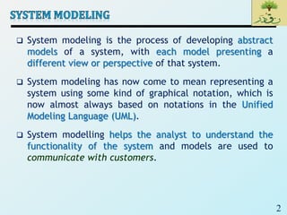
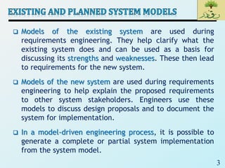


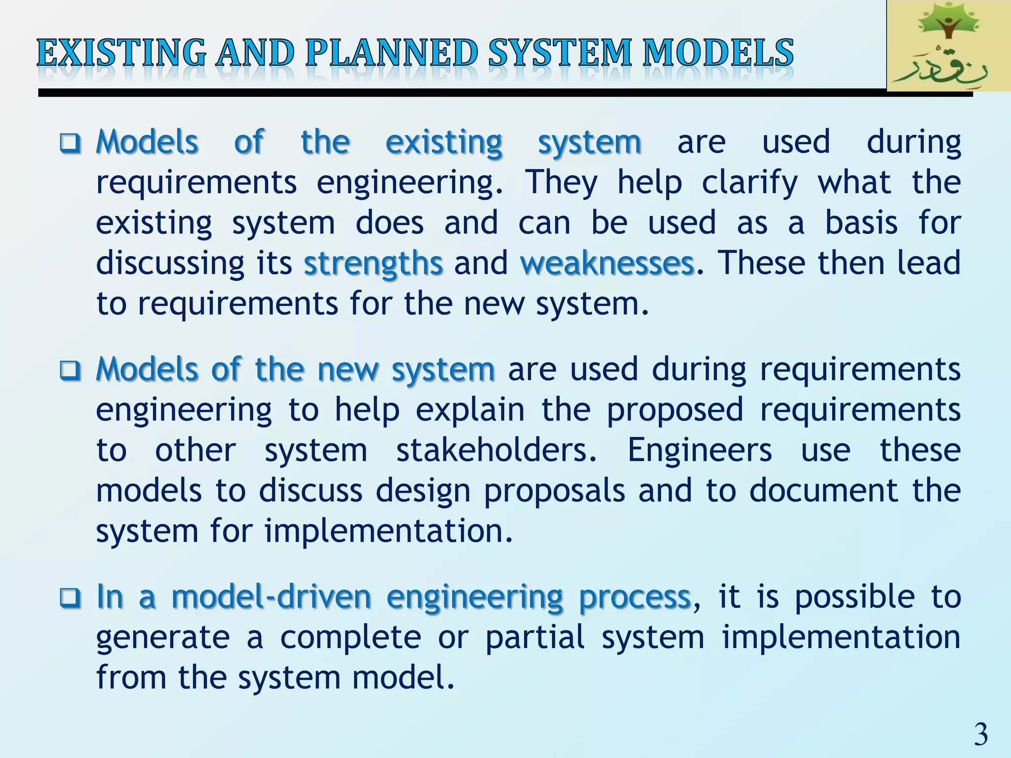


System modeling is the process of developing abstract models of a system using graphical notations like the Unified Modeling Language (UML) to represent different views of a system. Models help analysts understand system functionality and communicate with customers. Models of existing and new systems are used during requirements engineering to clarify current systems, discuss strengths/weaknesses, and explain proposed requirements.
System modeling uses graphical notations like UML to develop models for both existing and new systems during requirements engineering.
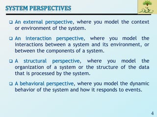
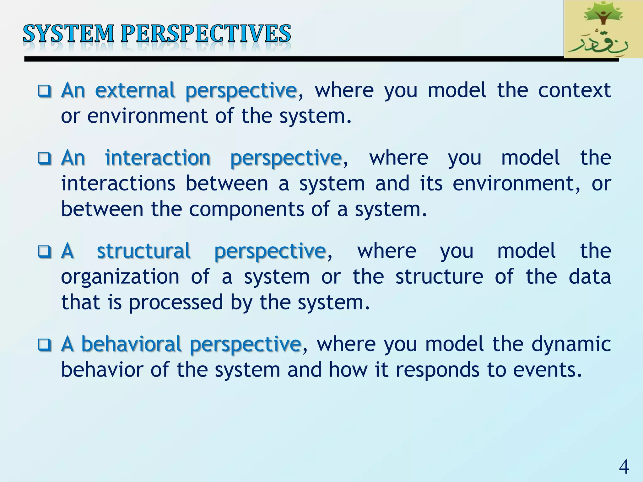
Modeling perspectives include external, interaction, structural, and behavioral views, with UML serving as a standard for object-oriented software.
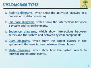
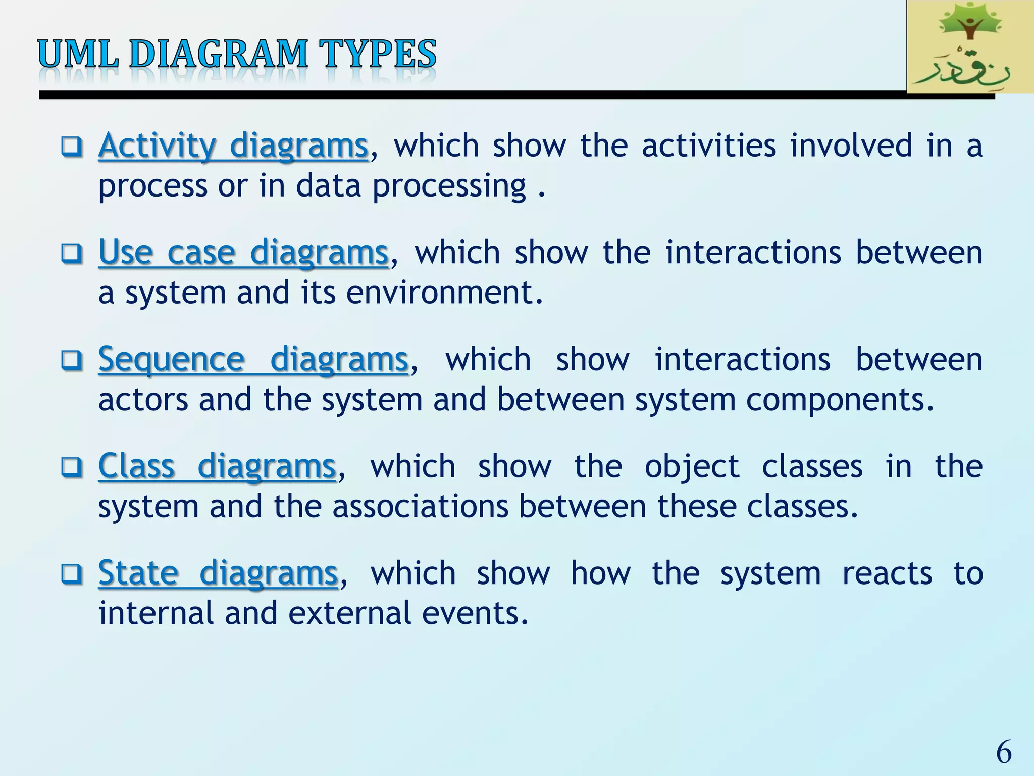
Activity, use case, sequence, class, and state diagrams are key UML diagrams used to illustrate system interactions and structures.
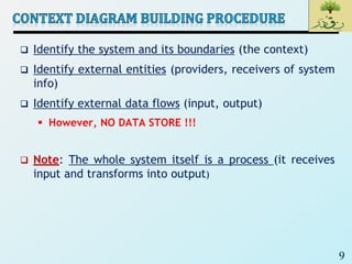
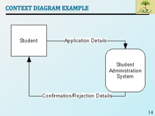
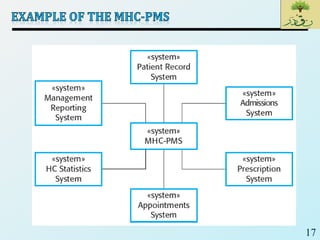
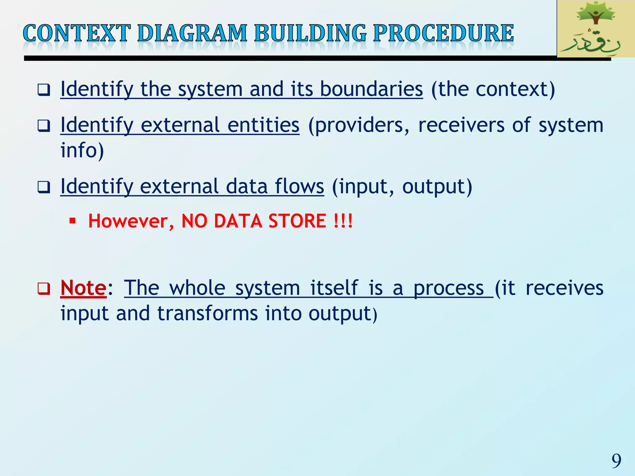
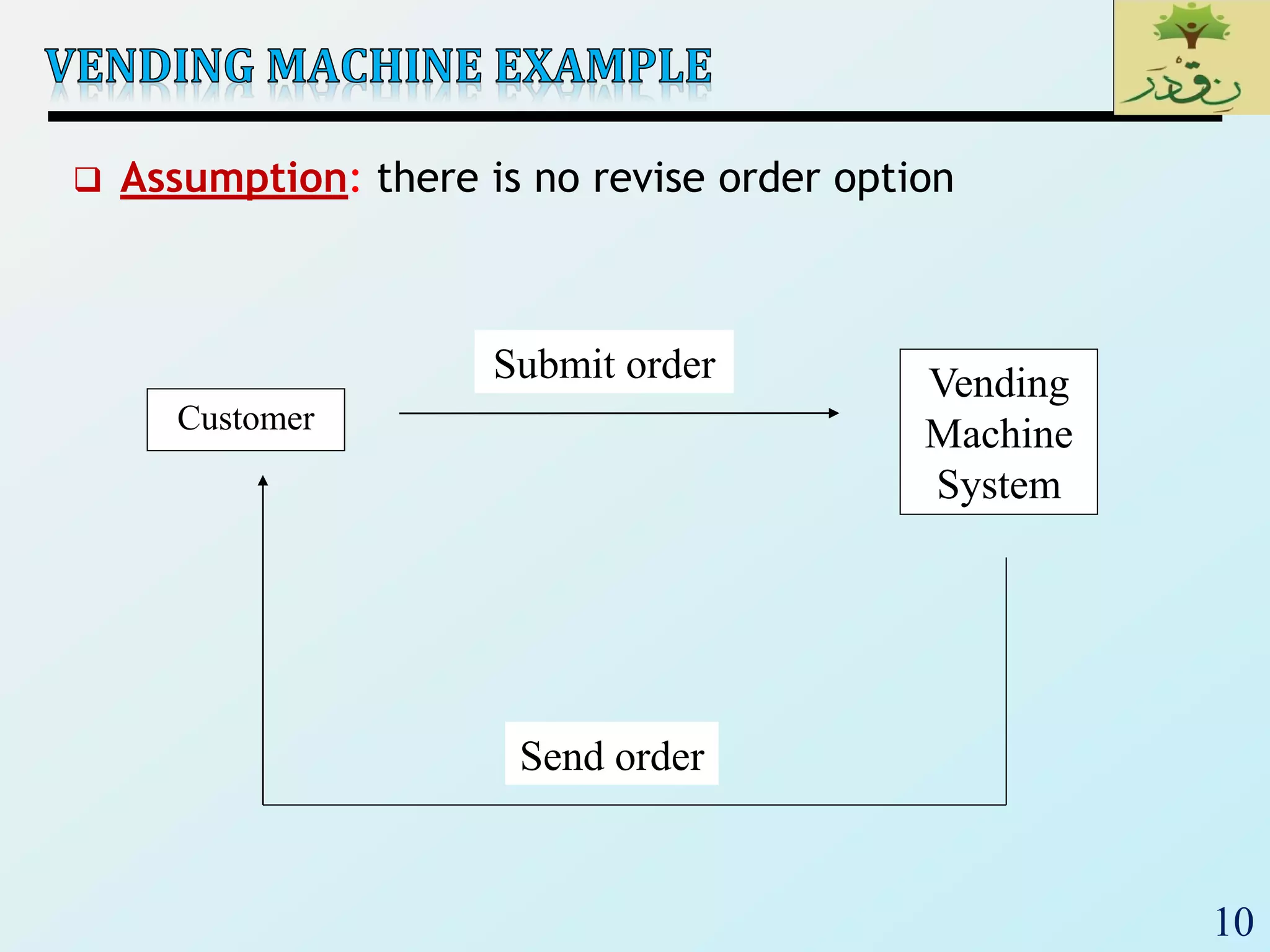
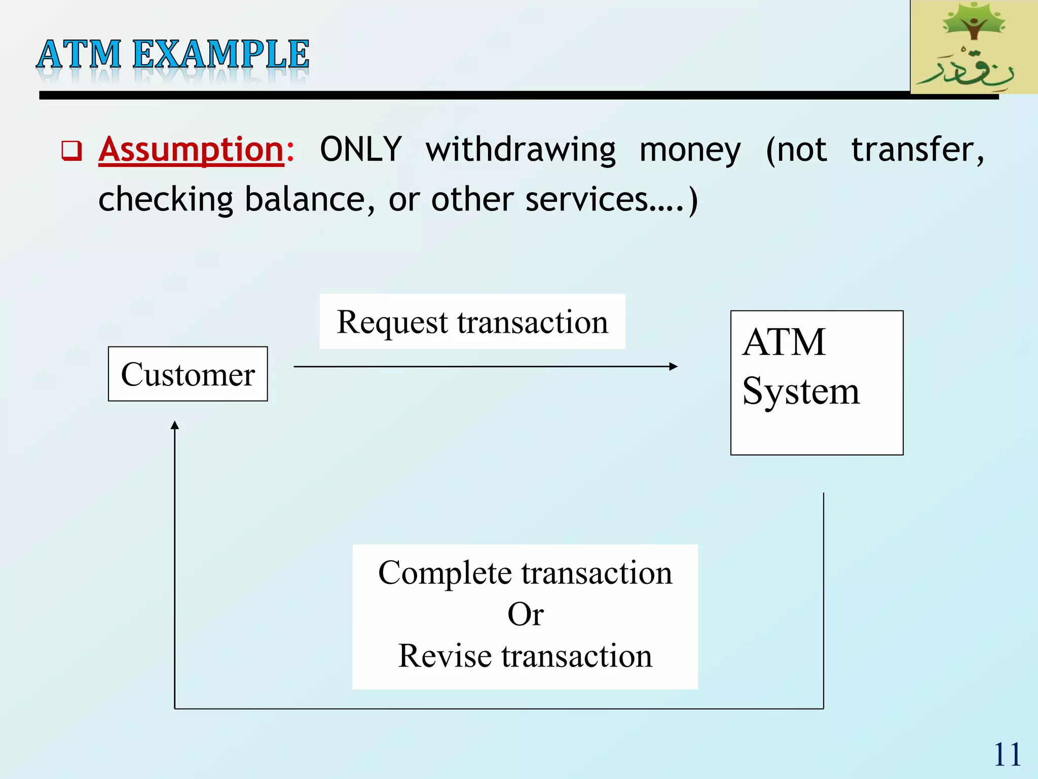
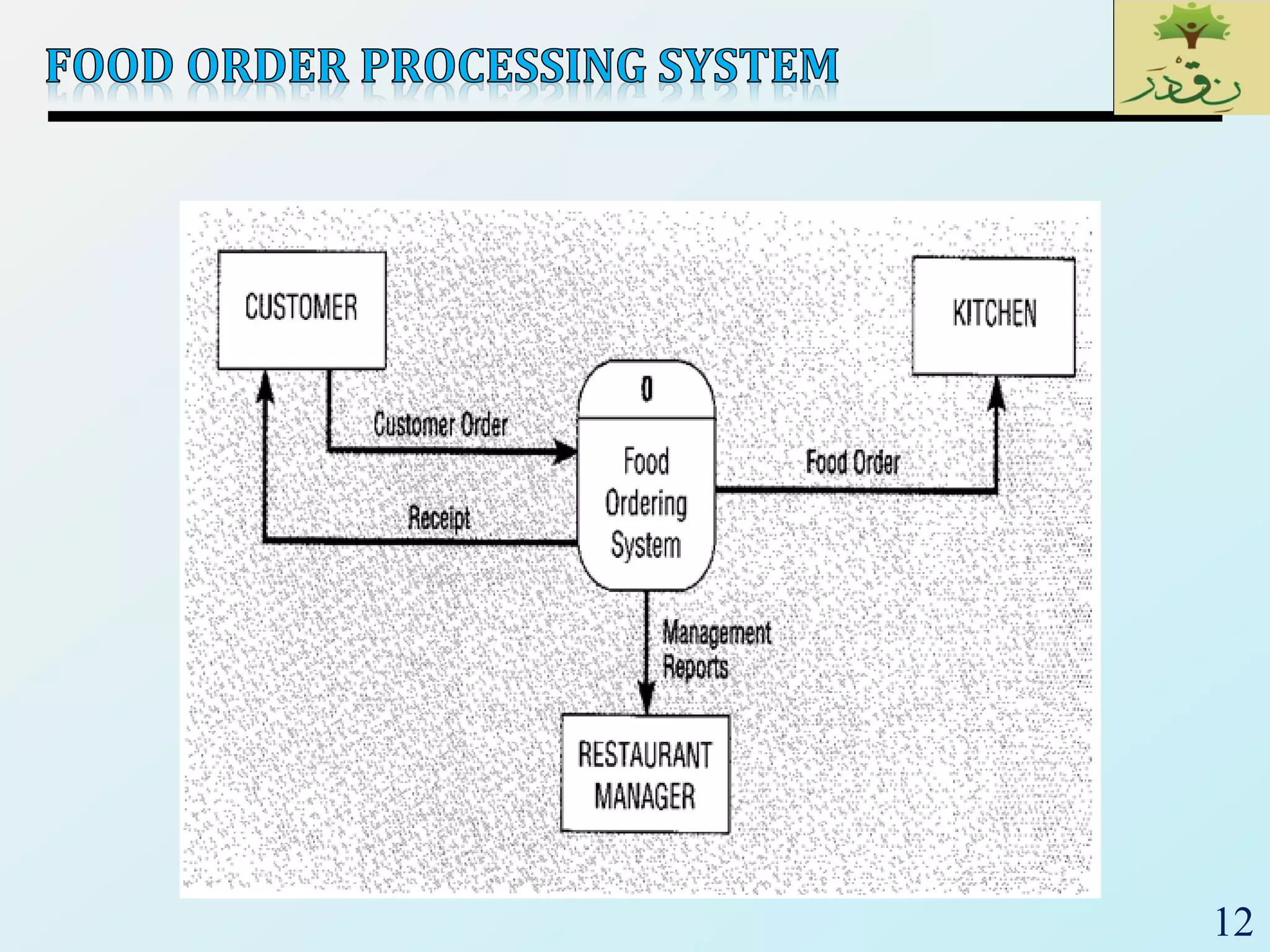
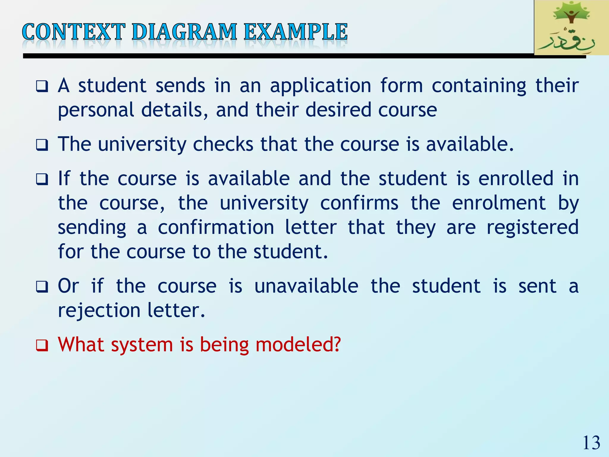
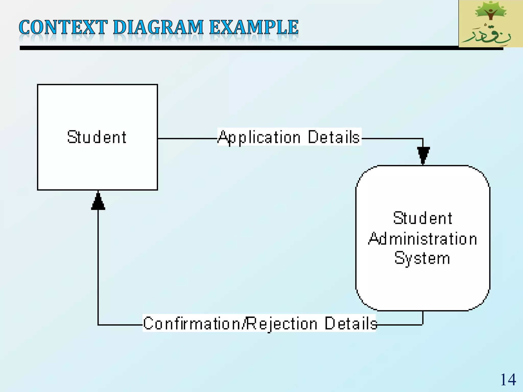
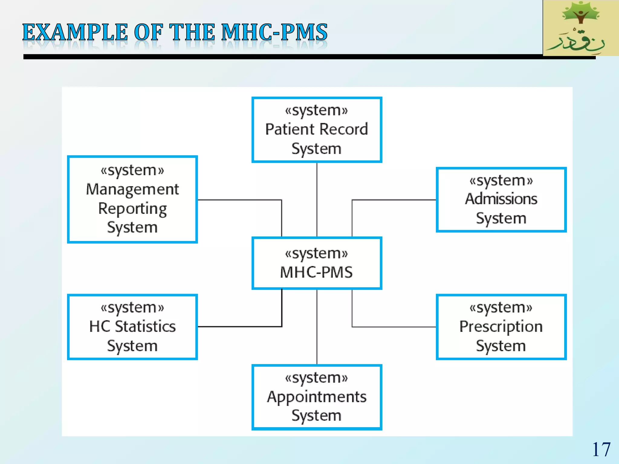
Context diagrams identify system boundaries, external entities, and data flows, while assumptions guide modeling of specific system interactions.
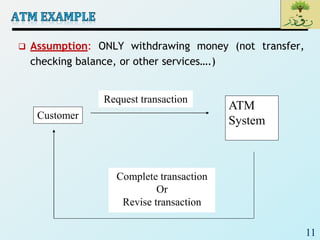
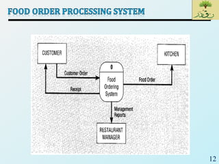
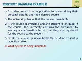
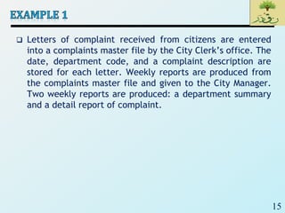
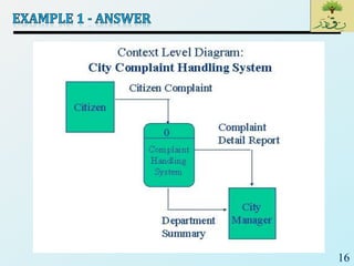
Examples illustrate modeling assumed operations like withdrawing money at ATMs, student enrollment processes, and complaint management by a city's office.


