Downloaded 434 times


![RS-232 Frame Start D0 D1 D2 D3 D4 D5 D6 D7 Stop 1 1 1 1 0 1 0 0 0 0 1 1 0 0 1 1 Every RS-232 Frame consists of: 1 start bit 8 data bits 1 stop bit (optional 1 parity bit) [a]= 0x61 = 0110 0001 P T tx = n .T clk T clk = 1/25 Mhz ,T tx = 1/9.6 Khz n = T tx /T clk , n = 25000/9.6](https://image.slidesharecdn.com/uartrs-232-101226143449-phpapp02/85/Uart-VHDL-RTL-design-tutorial-8-320.jpg)
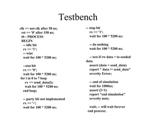
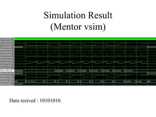
![Simulation Result (Mentor vsim) Sending [ 0xC1 ] = 1100 0001](https://image.slidesharecdn.com/uartrs-232-101226143449-phpapp02/85/Uart-VHDL-RTL-design-tutorial-14-320.jpg)


![FPGA over-all Test When buttons is pushed , PC receive : [a]= 0x61 PC send data to FPGA : data are displayed on leds => Use HyperTerminal to send and receive data receiver transmitter start debounce data=[a]= 0x61 tx rx Data_ready data PC PC](https://image.slidesharecdn.com/uartrs-232-101226143449-phpapp02/85/Uart-VHDL-RTL-design-tutorial-42-320.jpg)

![RS-232 Frame Start D0 D1 D2 D3 D4 D5 D6 D7 Stop 1 1 1 1 0 1 0 0 0 0 1 1 0 0 1 1 Every RS-232 Frame consists of: 1 start bit 8 data bits 1 stop bit (optional 1 parity bit) [a]= 0x61 = 0110 0001 P T tx = n .T clk T clk = 1/25 Mhz ,T tx = 1/9.6 Khz n = T tx /T clk , n = 25000/9.6](https://image.slidesharecdn.com/uartrs-232-101226143449-phpapp02/75/Uart-VHDL-RTL-design-tutorial-8-2048.jpg)

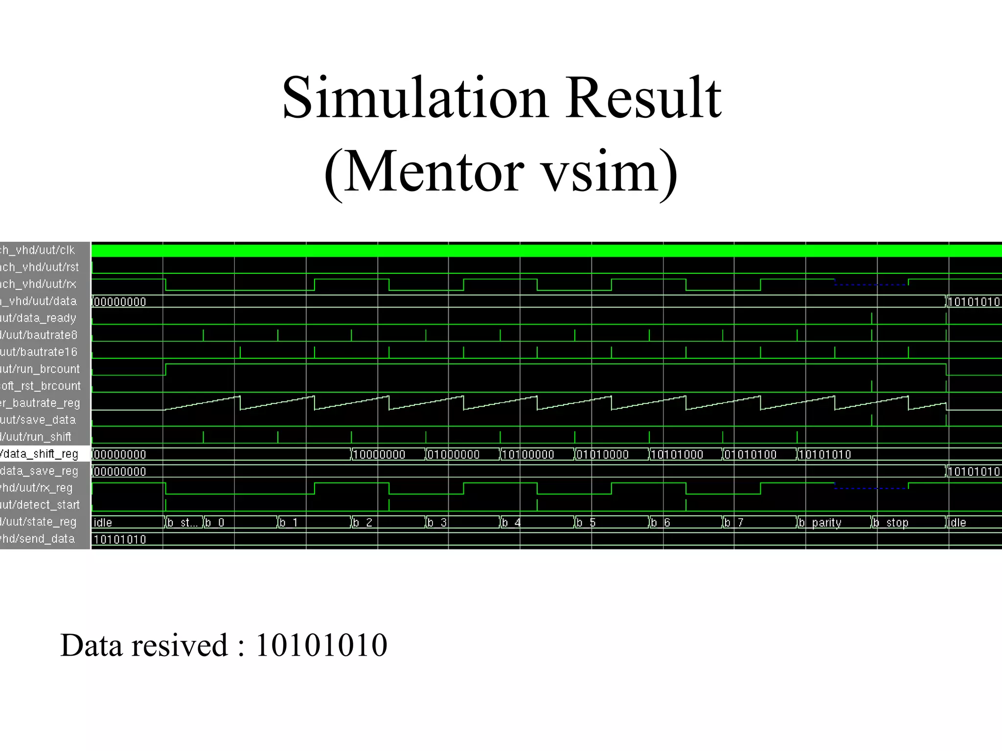
![Simulation Result (Mentor vsim) Sending [ 0xC1 ] = 1100 0001](https://image.slidesharecdn.com/uartrs-232-101226143449-phpapp02/75/Uart-VHDL-RTL-design-tutorial-14-2048.jpg)


![FPGA over-all Test When buttons is pushed , PC receive : [a]= 0x61 PC send data to FPGA : data are displayed on leds => Use HyperTerminal to send and receive data receiver transmitter start debounce data=[a]= 0x61 tx rx Data_ready data PC PC](https://image.slidesharecdn.com/uartrs-232-101226143449-phpapp02/75/Uart-VHDL-RTL-design-tutorial-42-2048.jpg)

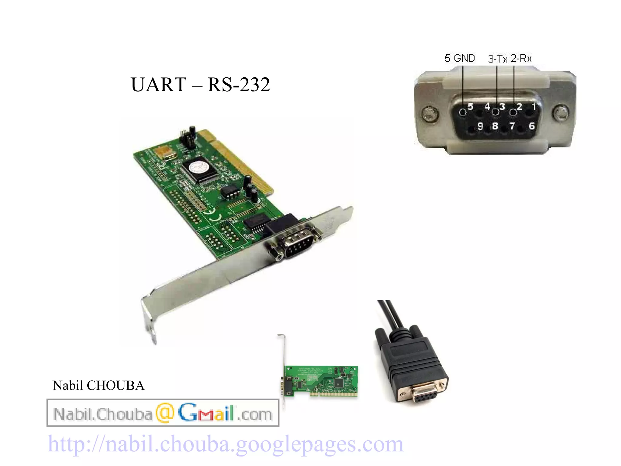
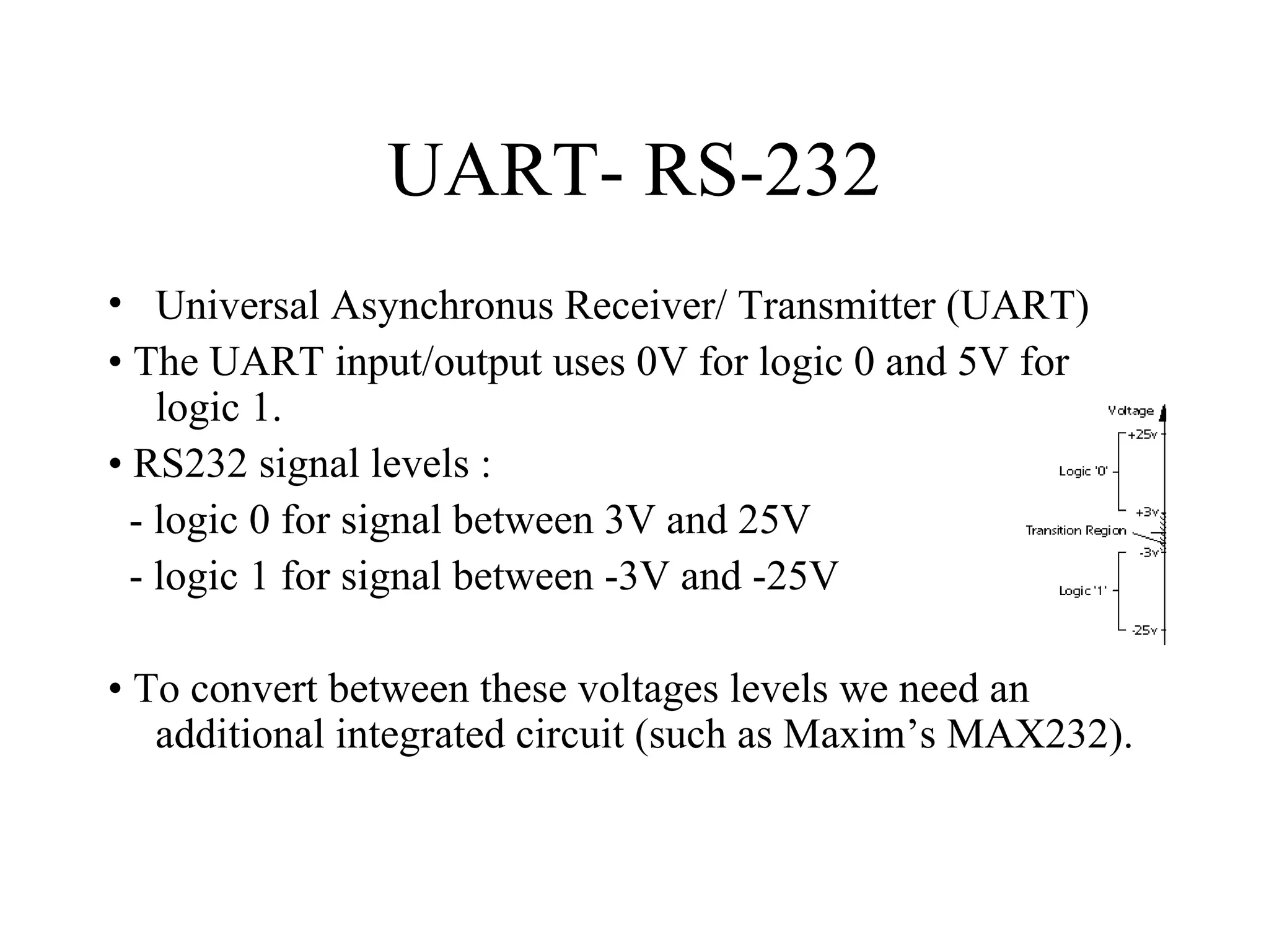
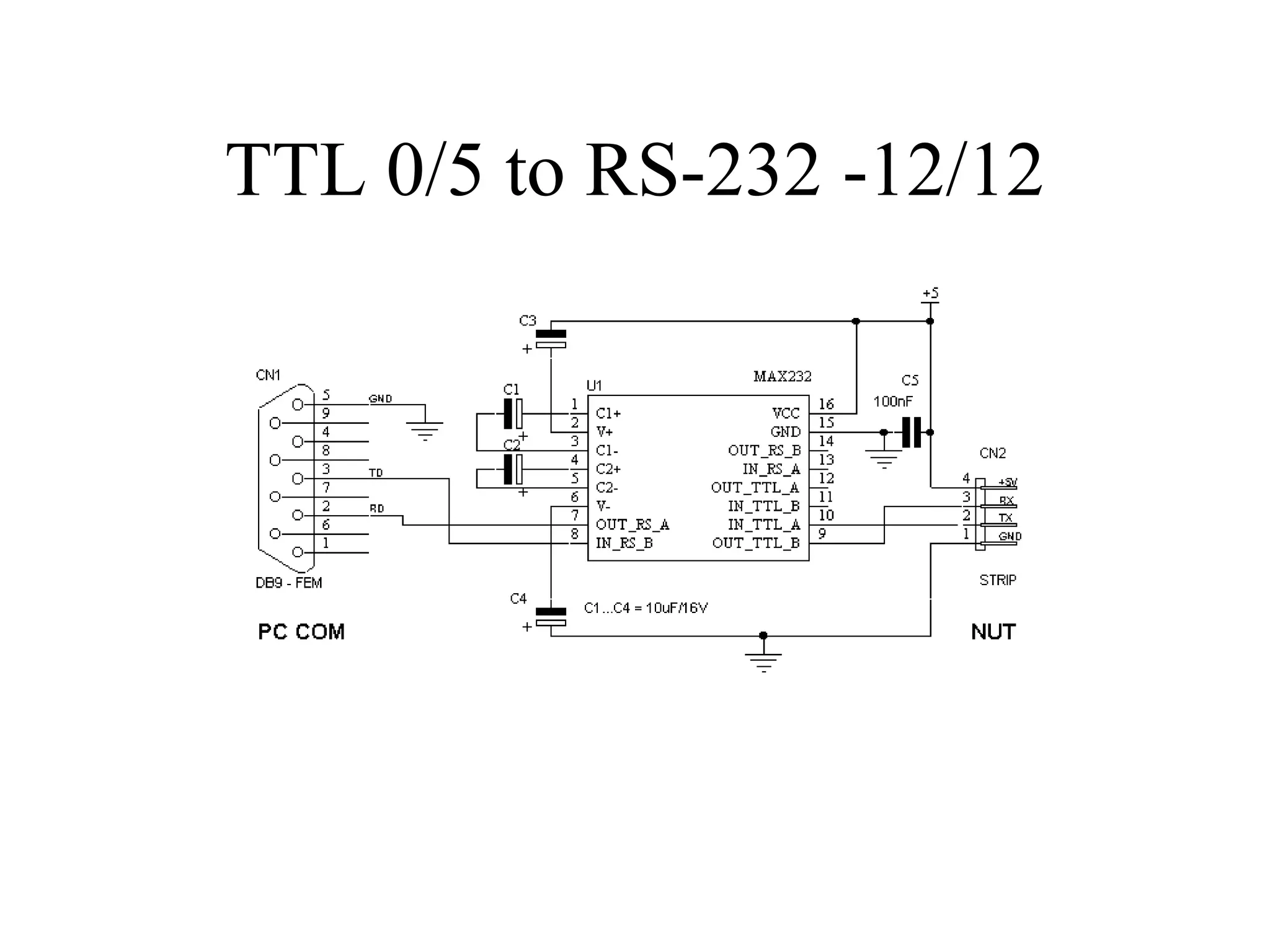
The document discusses UART (Universal Asynchronous Receiver/Transmitter) and RS-232 communication standards. It describes the voltage levels used, the need for a converter chip between UART and RS-232, synchronous vs asynchronous transmission, baud rates, frame formats, and provides VHDL code for a UART transmitter and receiver implementation including state machines and registers.
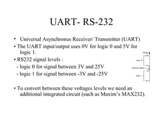
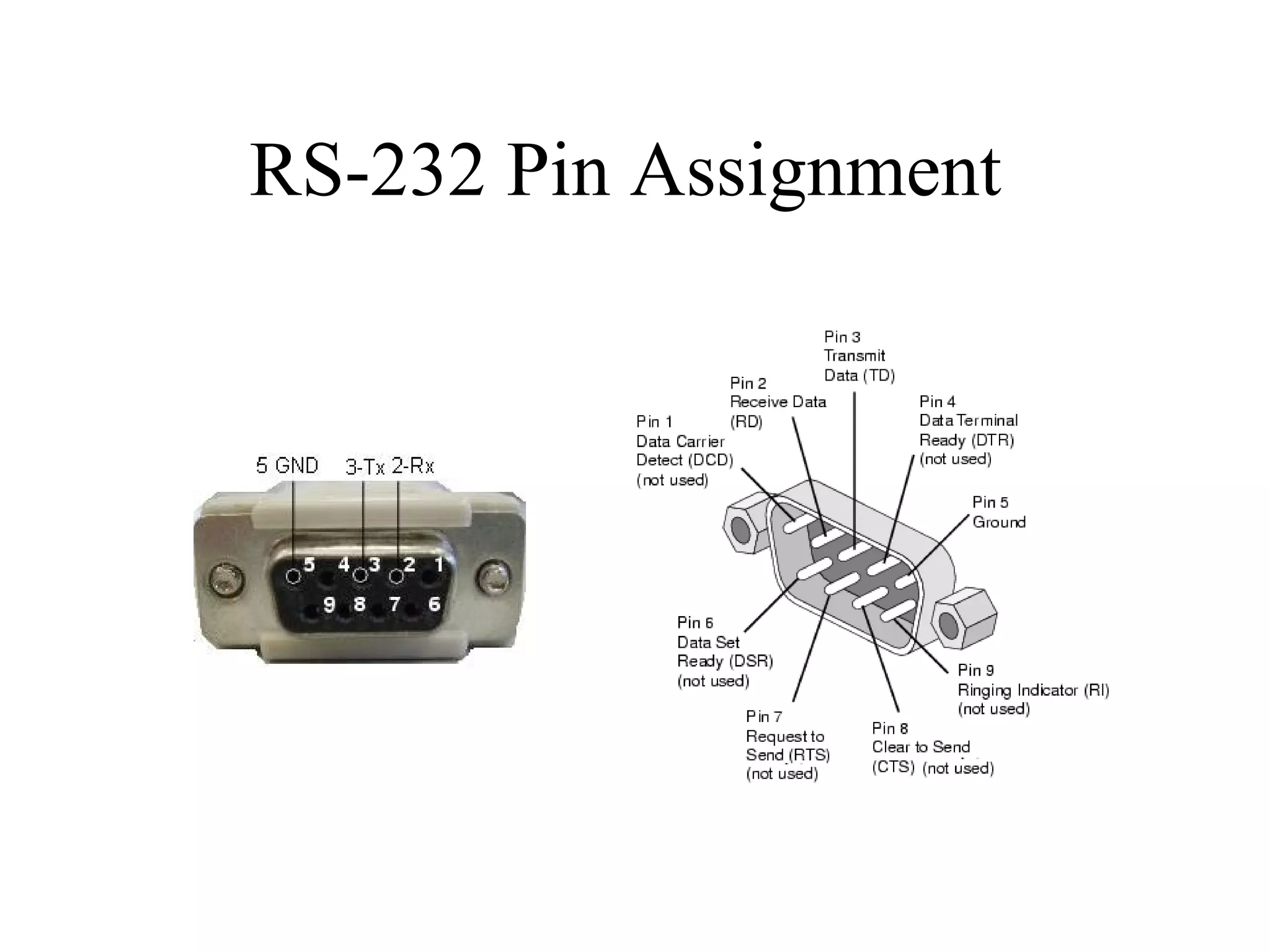
Overview of UART as Universal Asynchronous Receiver/Transmitter (UART) using logic levels of 0V and 5V for RS-232 signal levels.
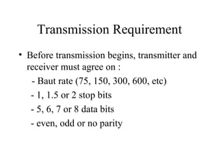
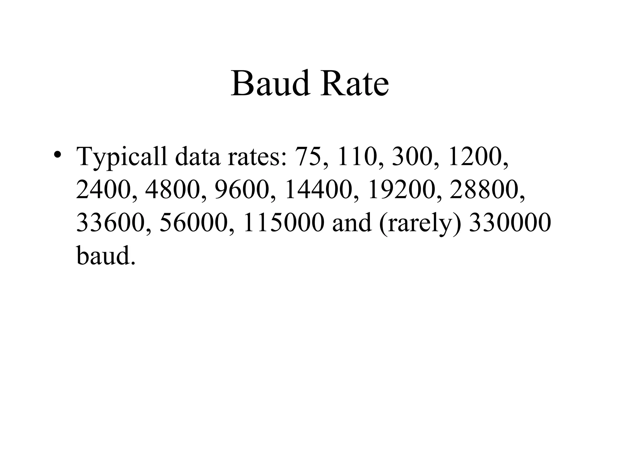
Details on typical baud rates ranging from 75 to 330000. Discusses requirements including baud rate, stop bits, data bits, and parity.Description of RS-232 frame consisting of start bit, data bits, stop bit, and optional parity bit.
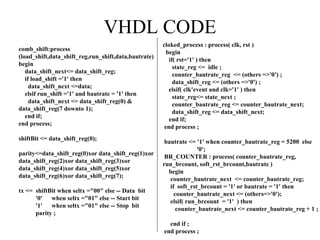
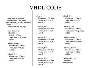
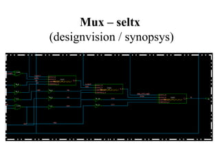
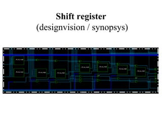
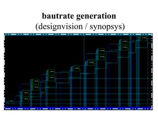
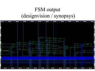
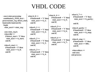
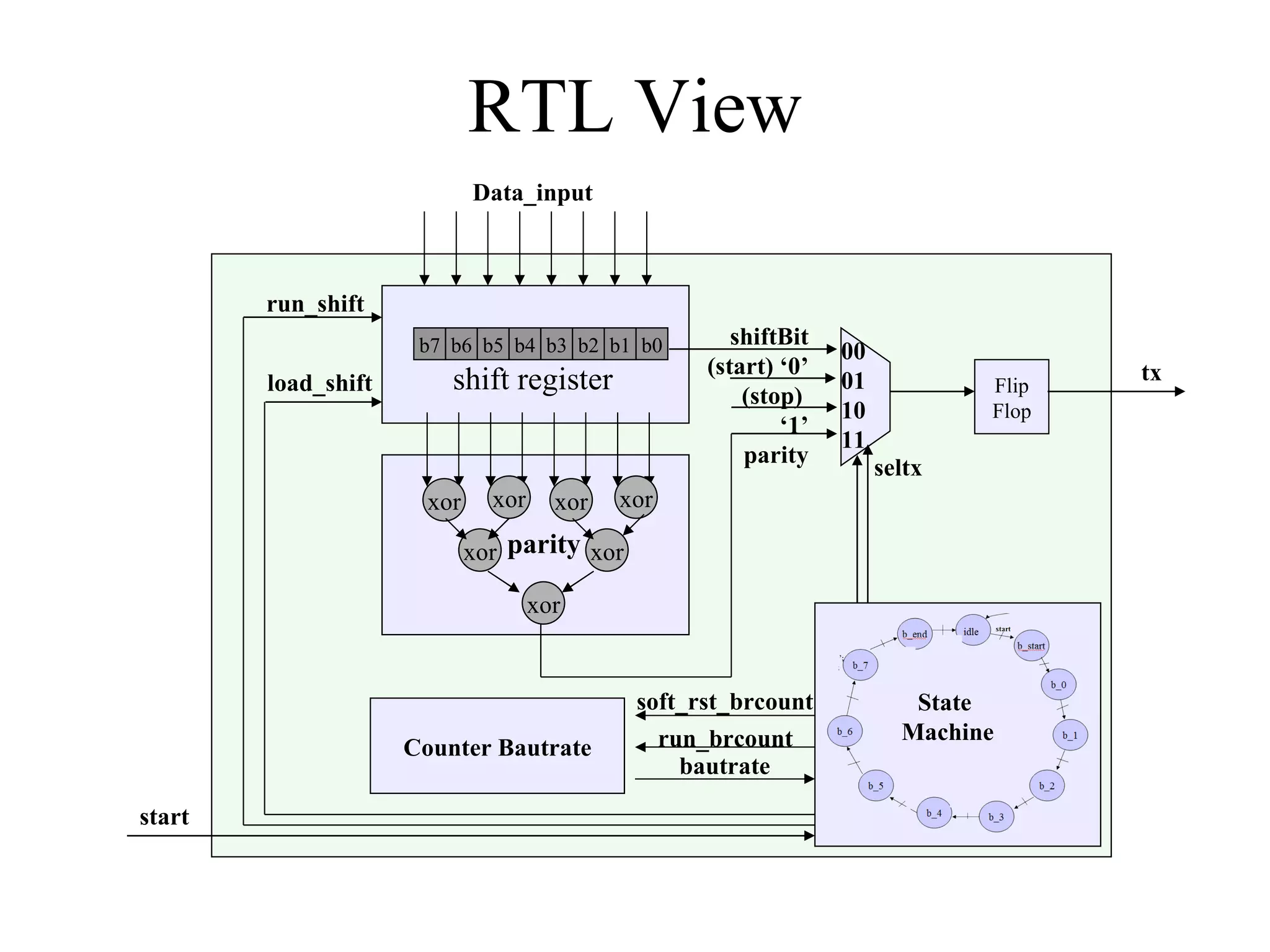
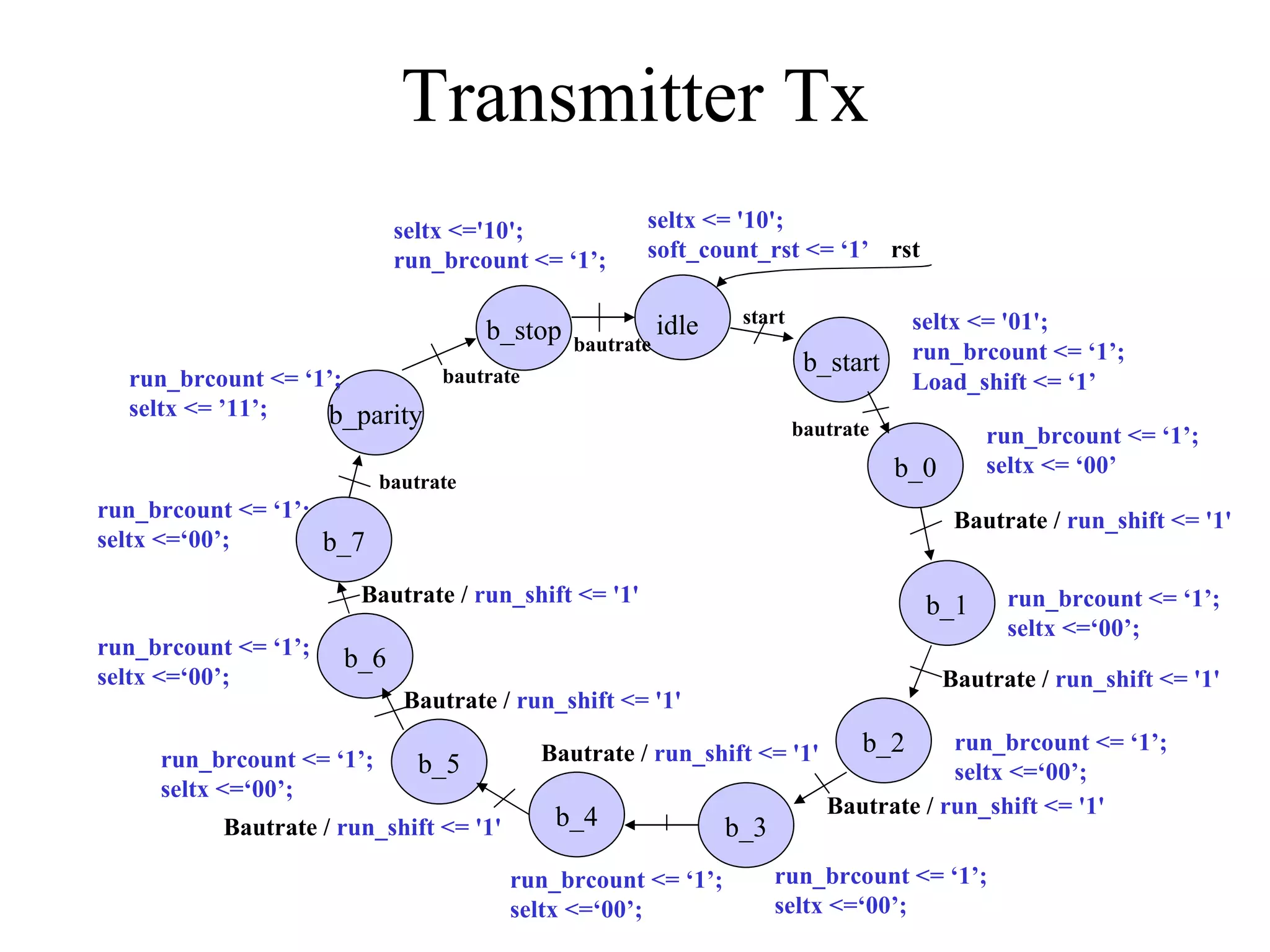
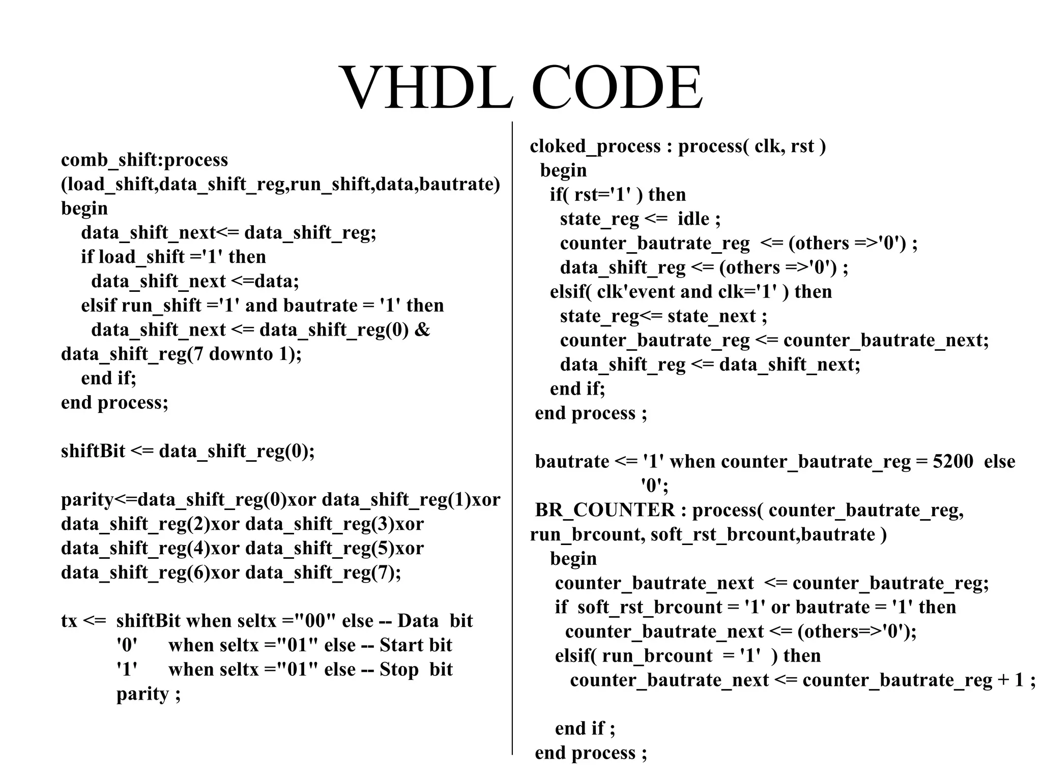
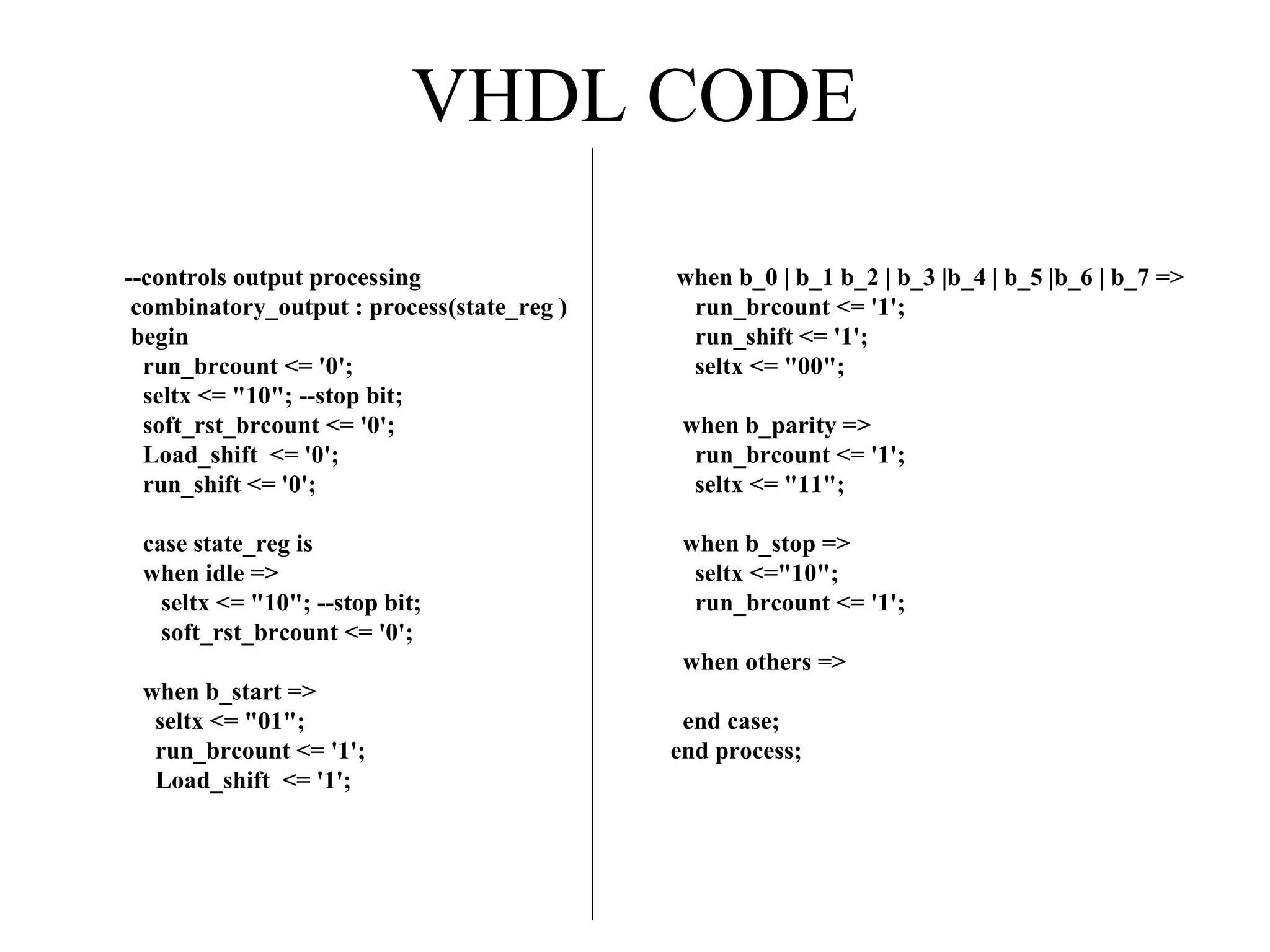
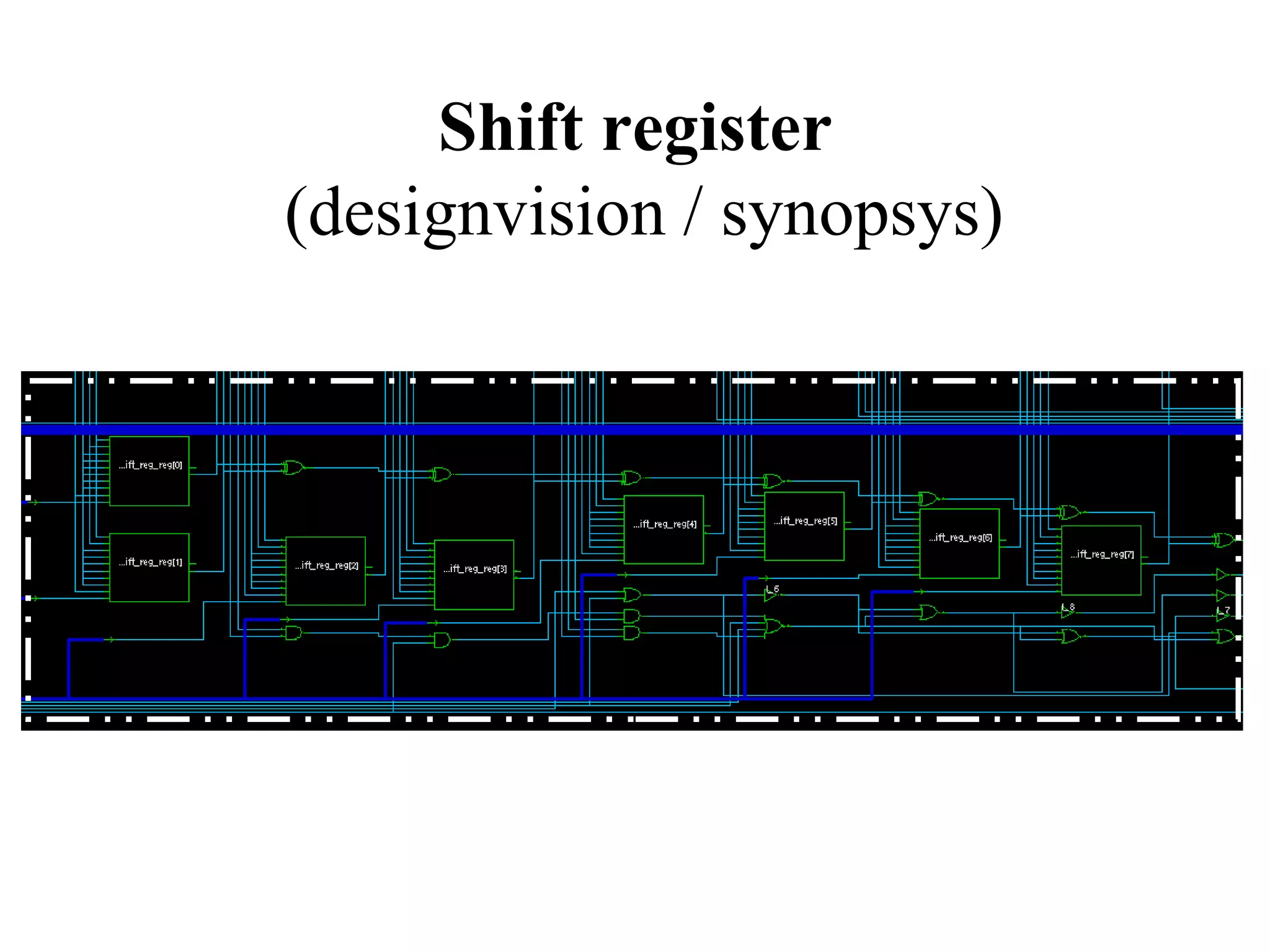
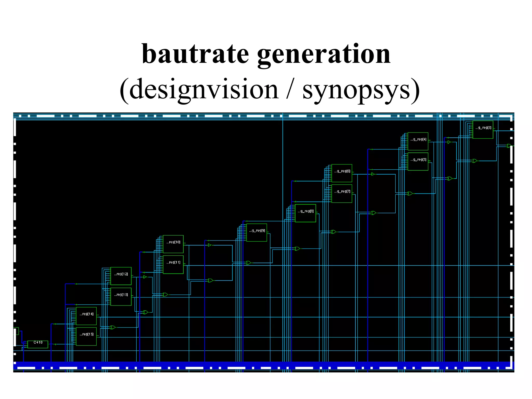
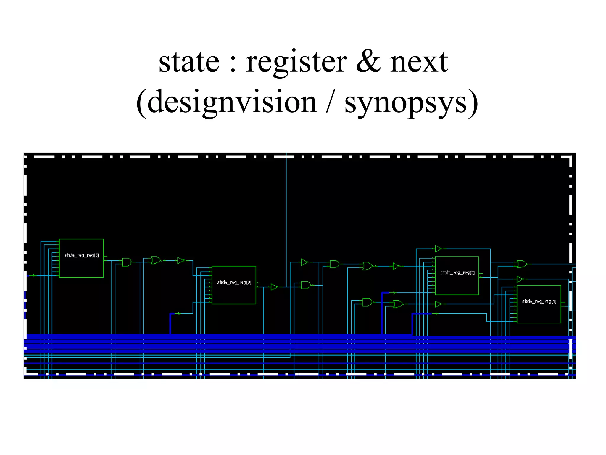
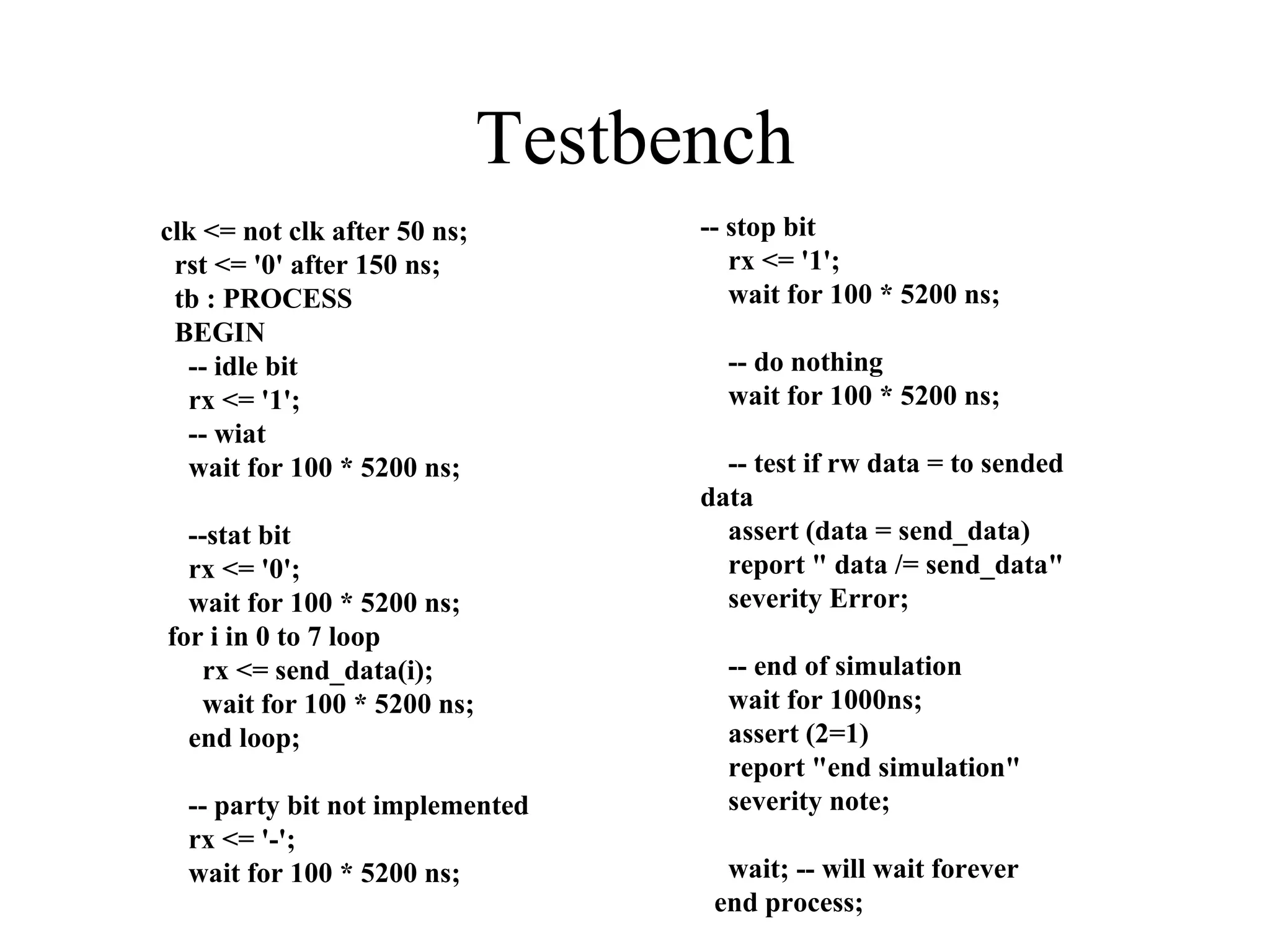
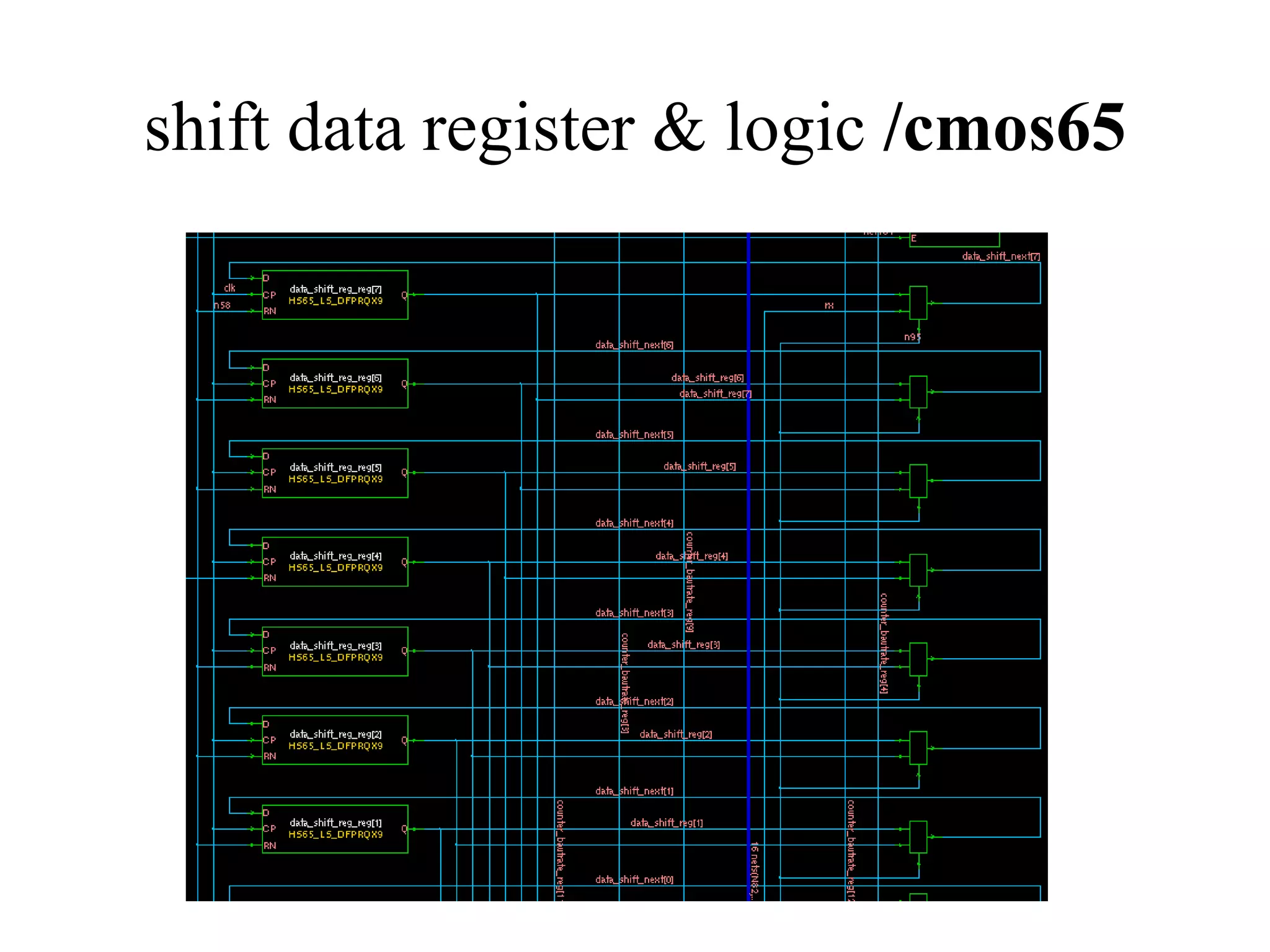
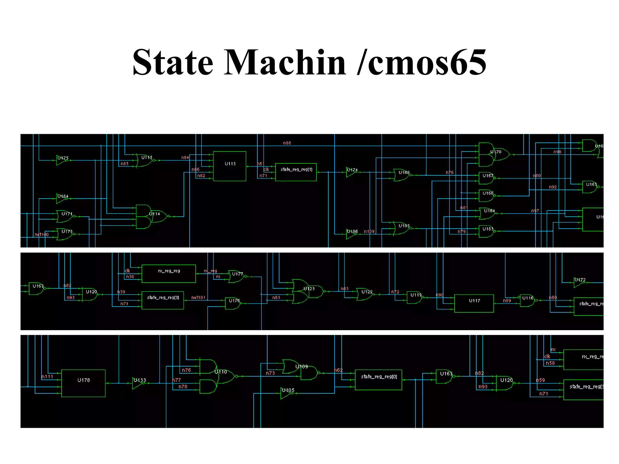
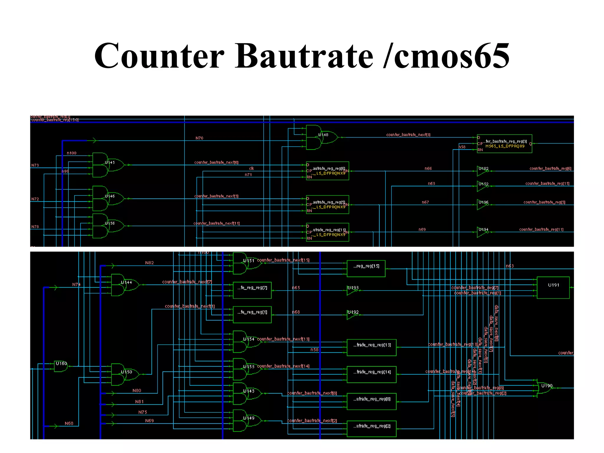
VHDL code for transmitter processes, including state machine, baud rate control, and shift register operations.
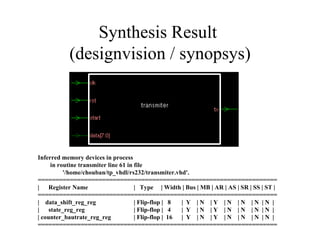
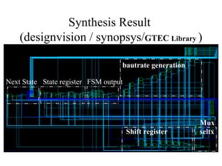
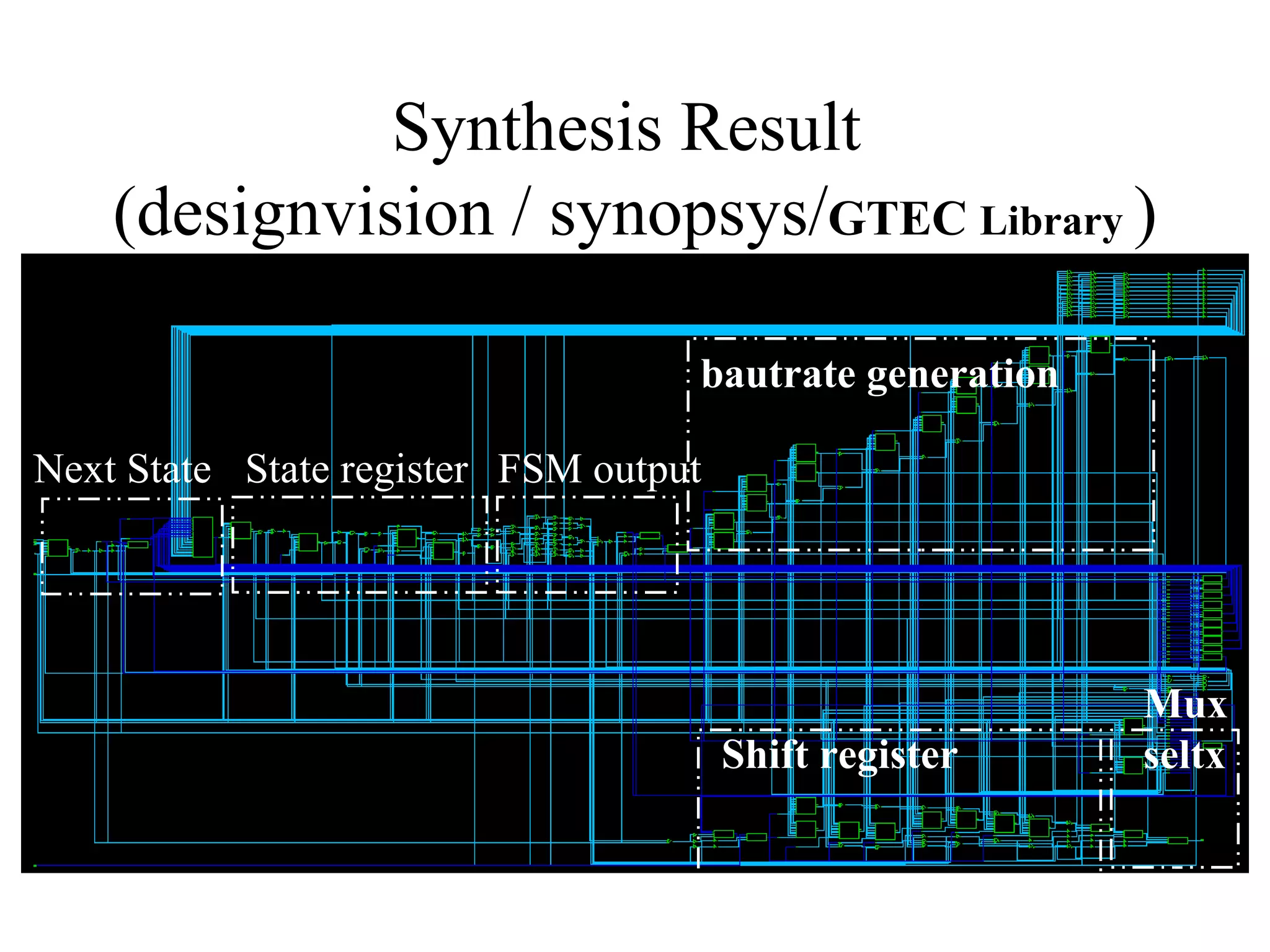
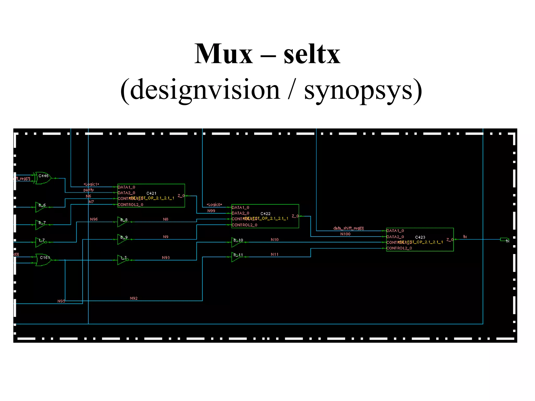
Presents simulation results of transmission and inferred memory devices in synthesis for the transmitter.
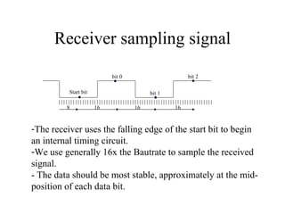
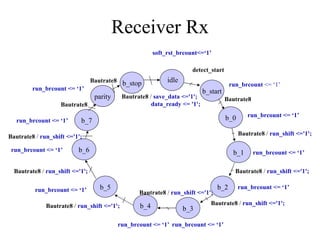
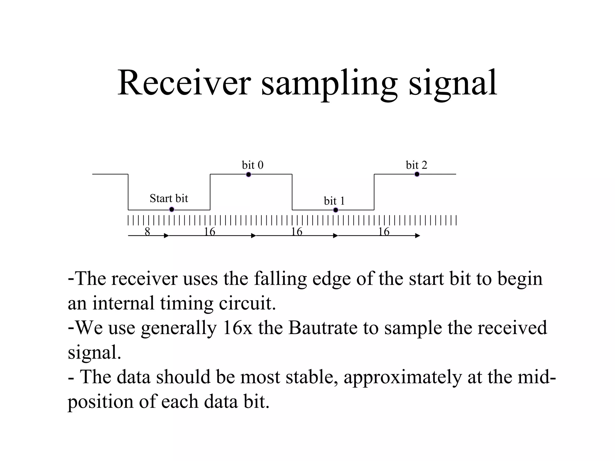
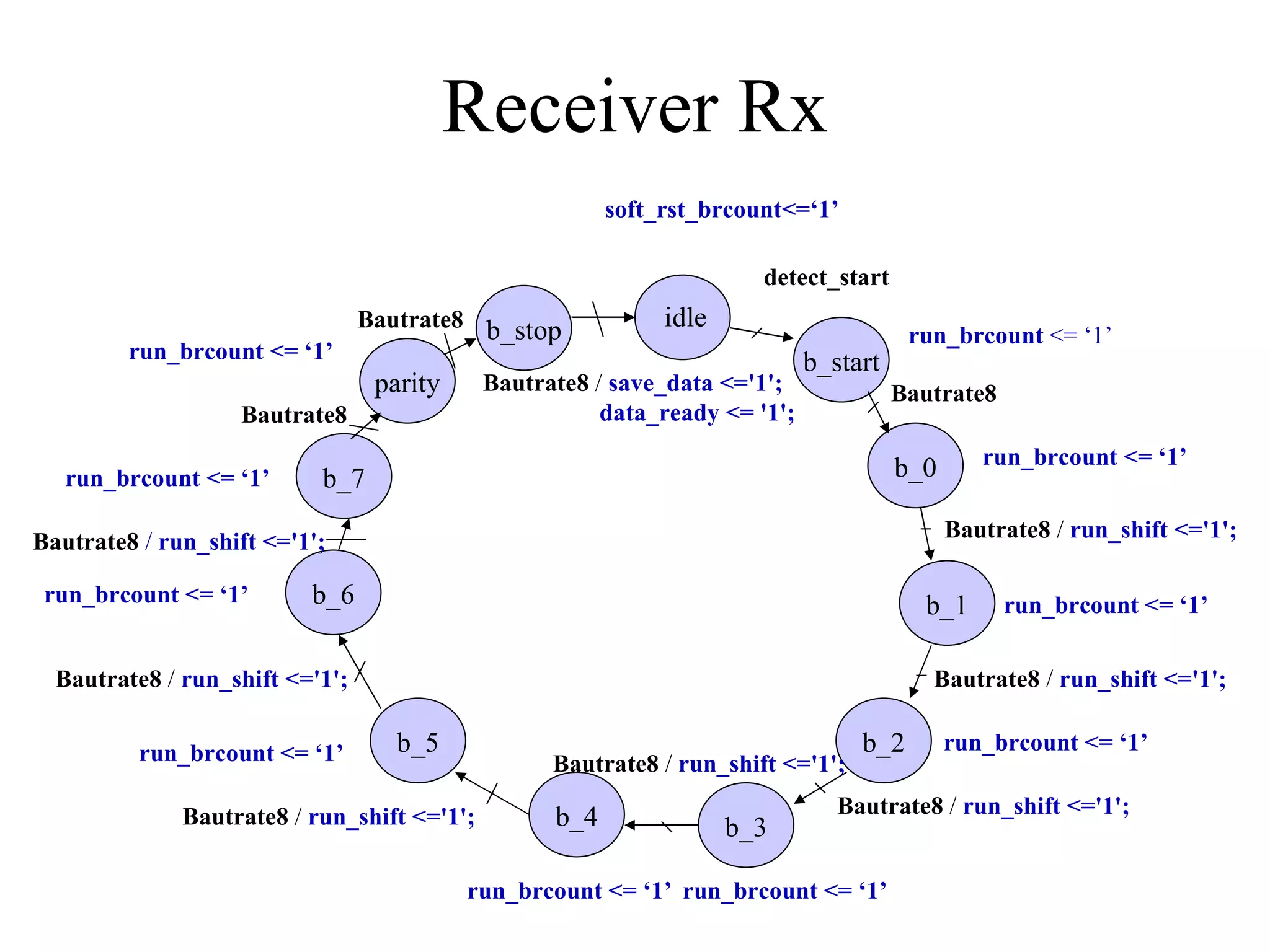
Receiver operation explanation, highlighting signal sampling, start bit detection, and use of counters.
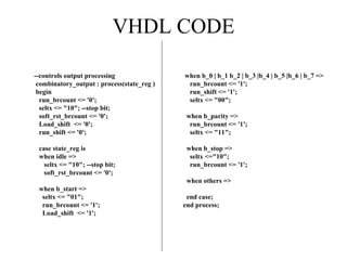
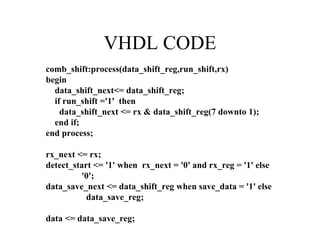
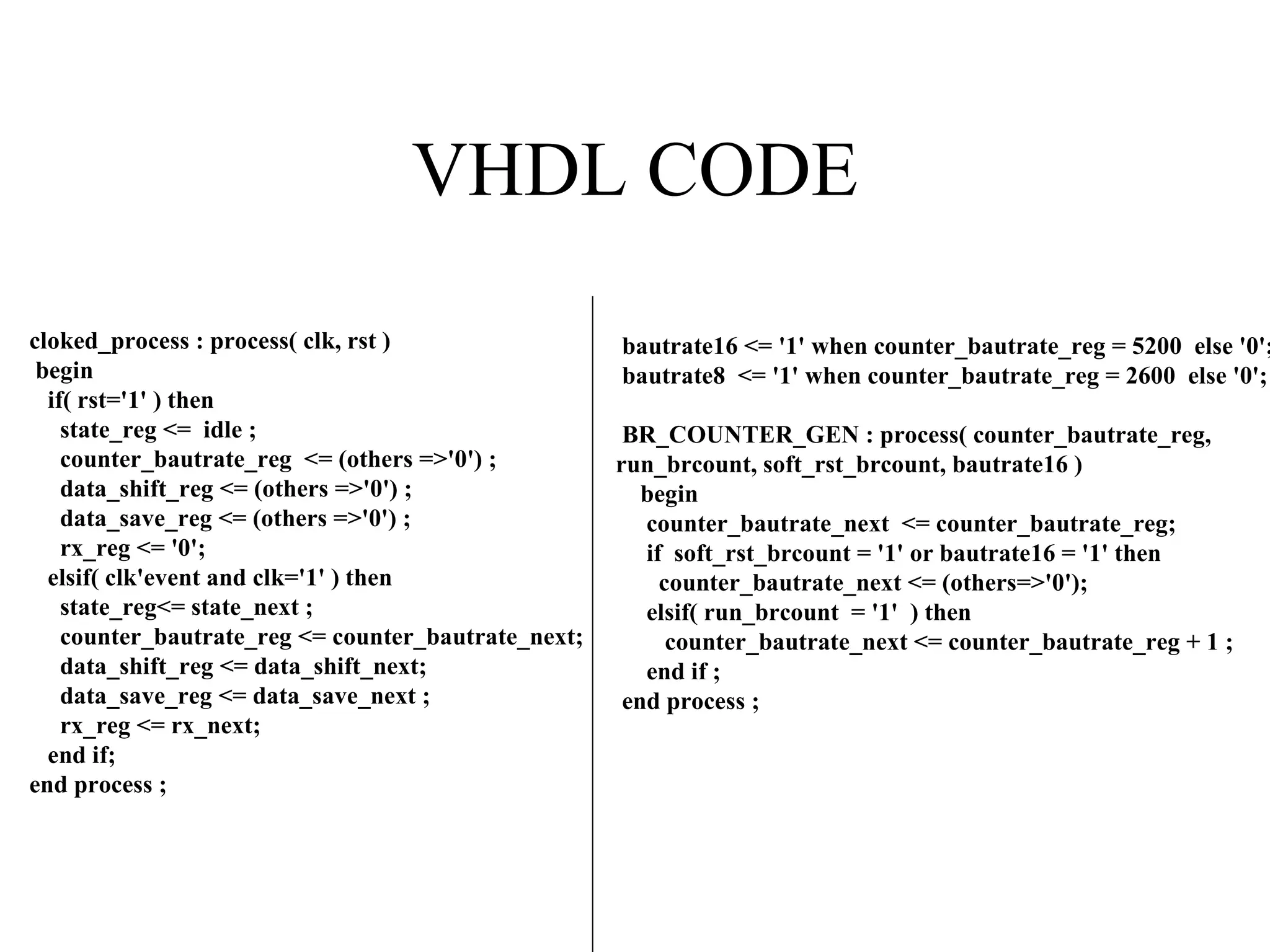
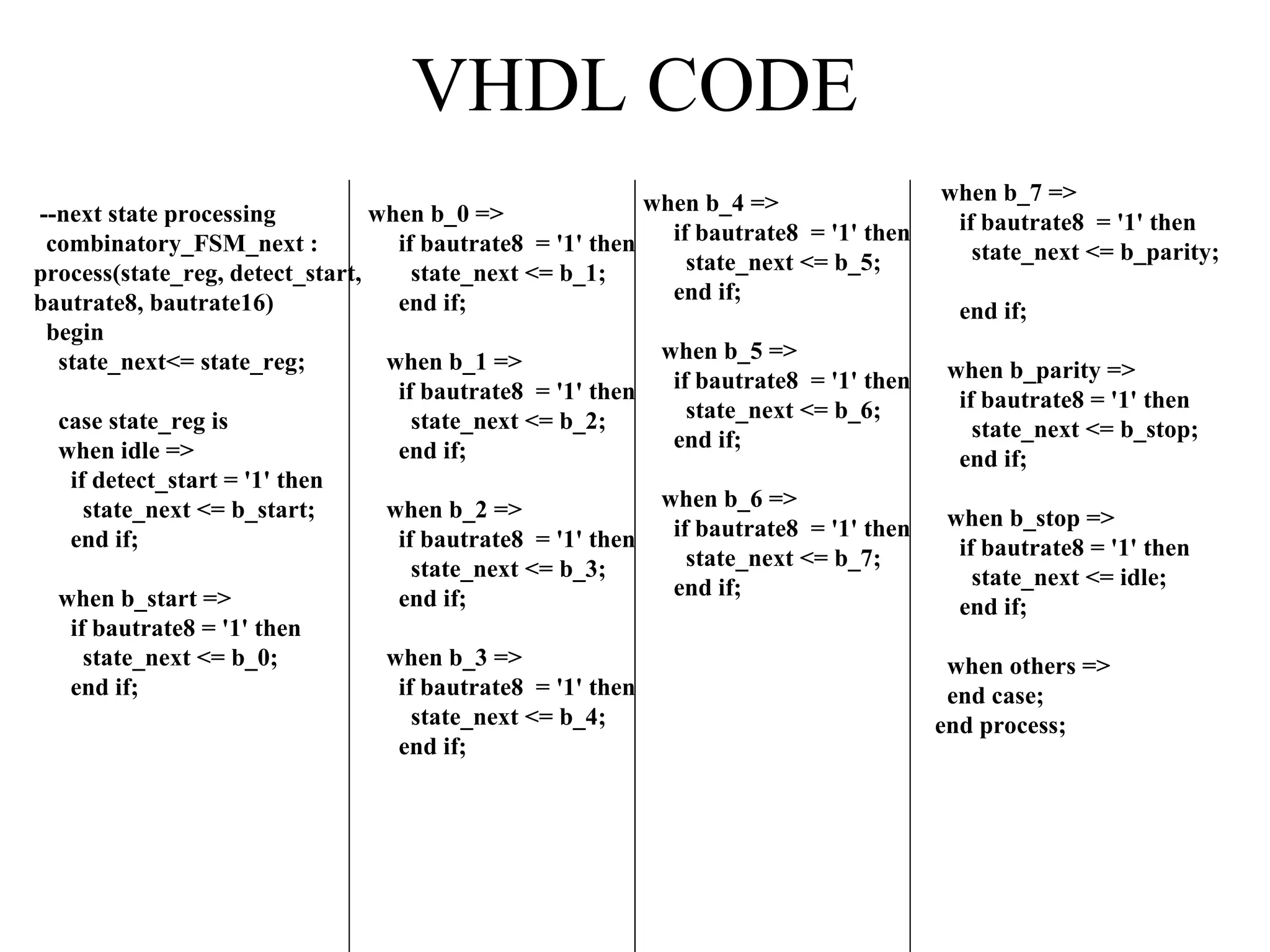
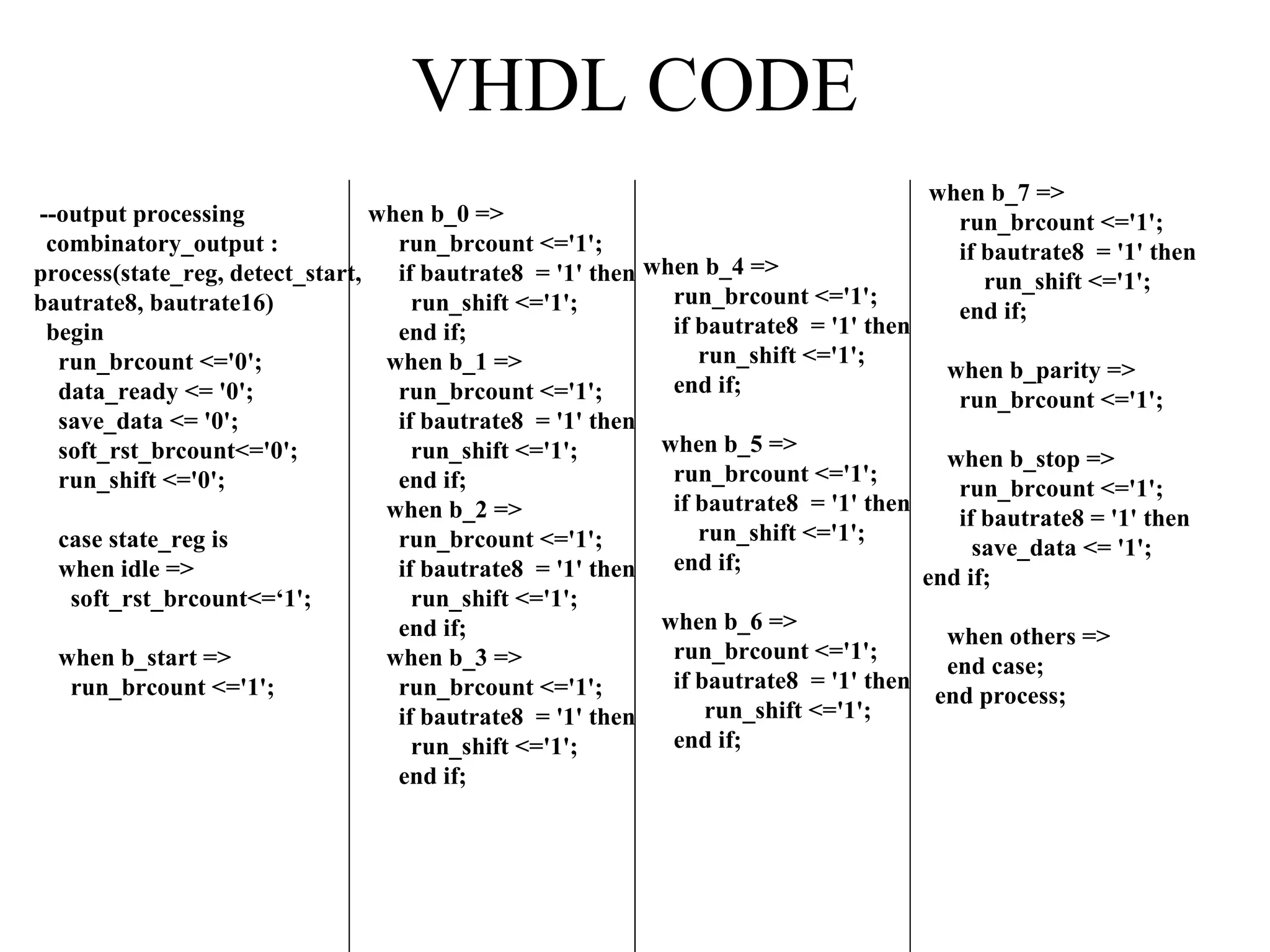
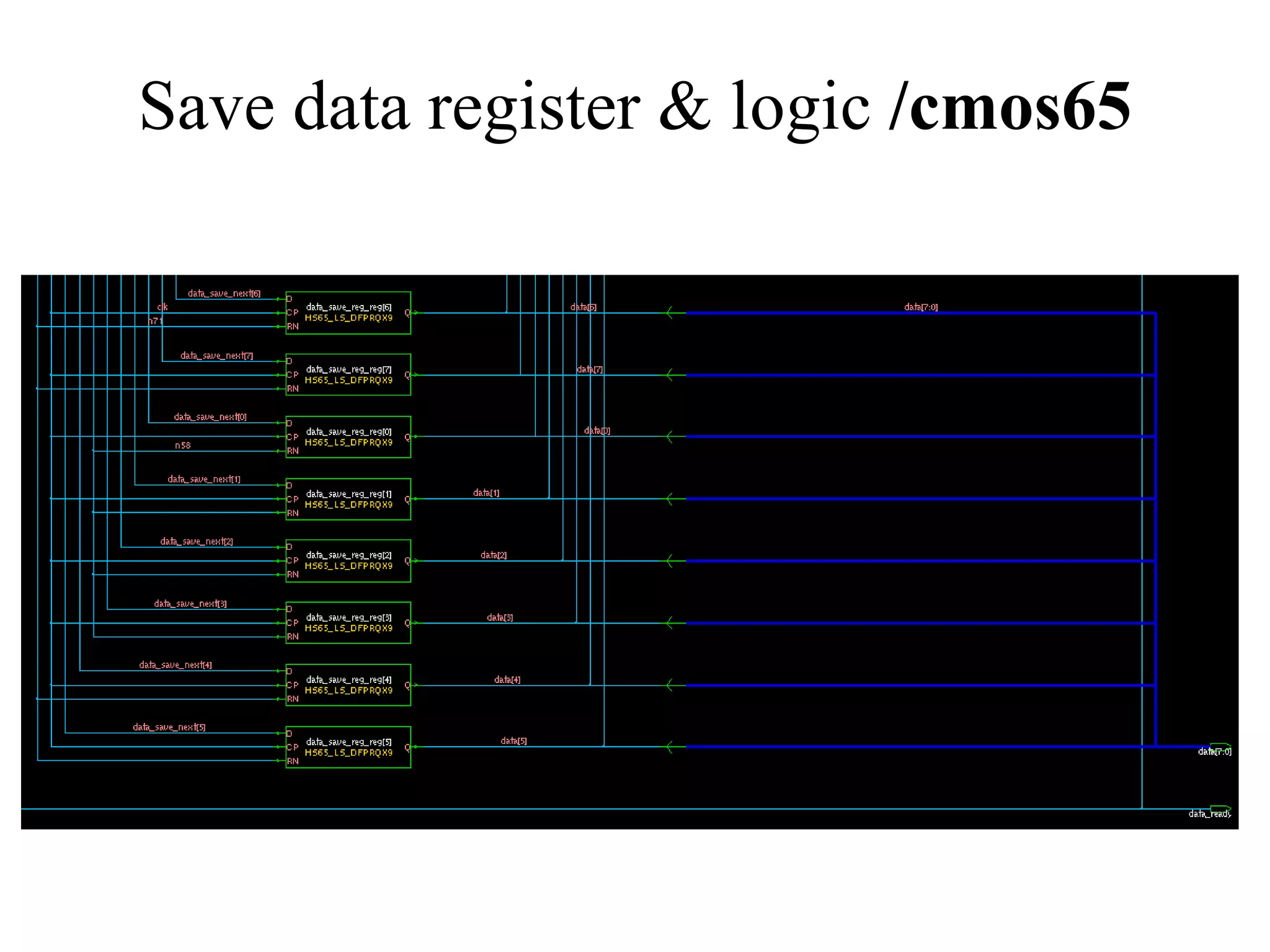
VHDL code for receiver processes focusing on state management, data saving, and output processing.
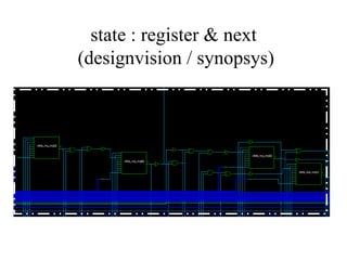
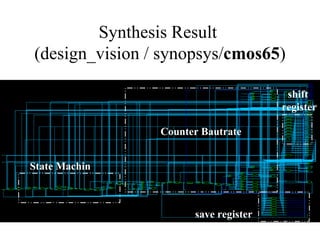
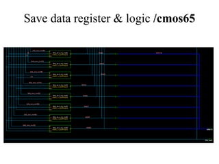
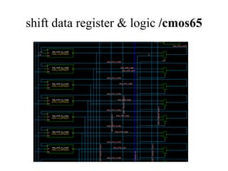
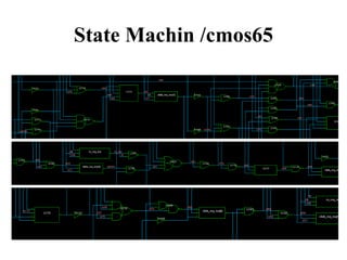
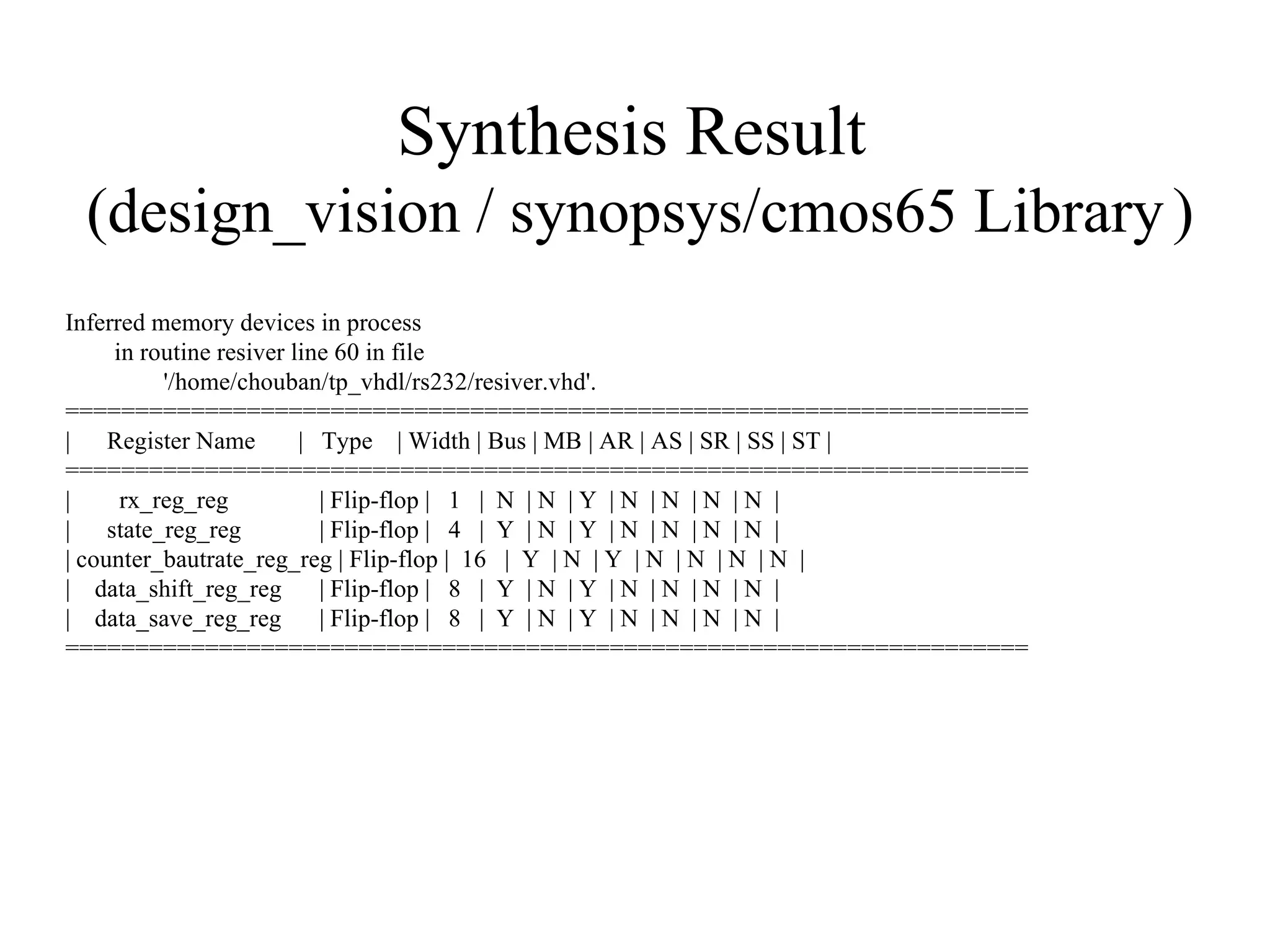
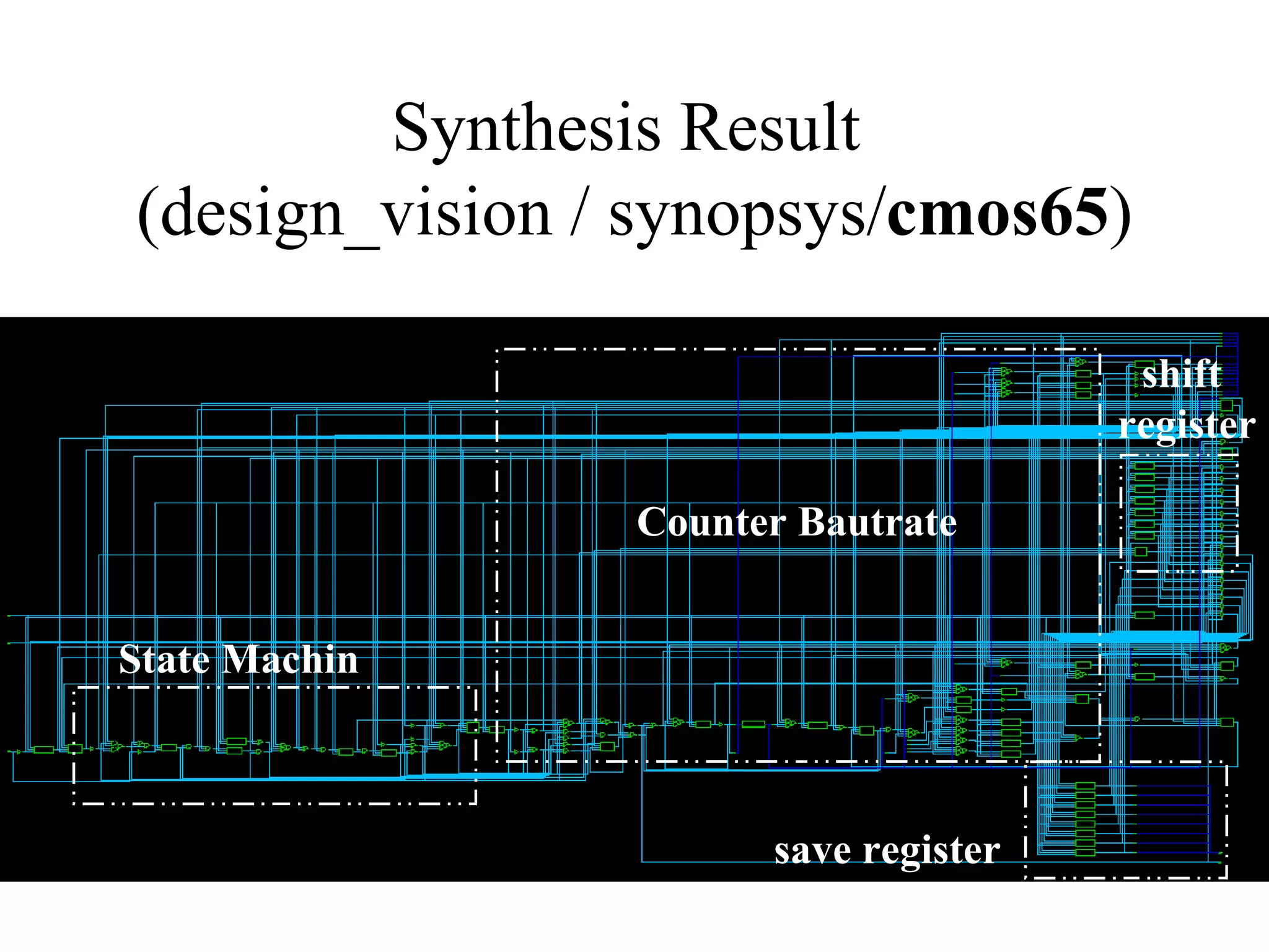
Results of simulation and synthesis for the receiver, detailing register types, widths, and inferred components.
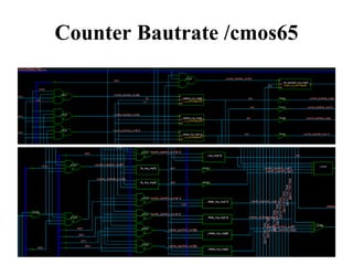
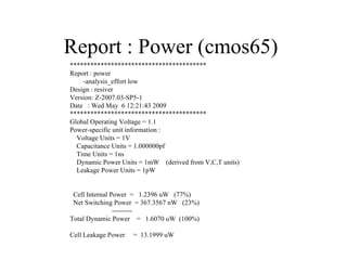
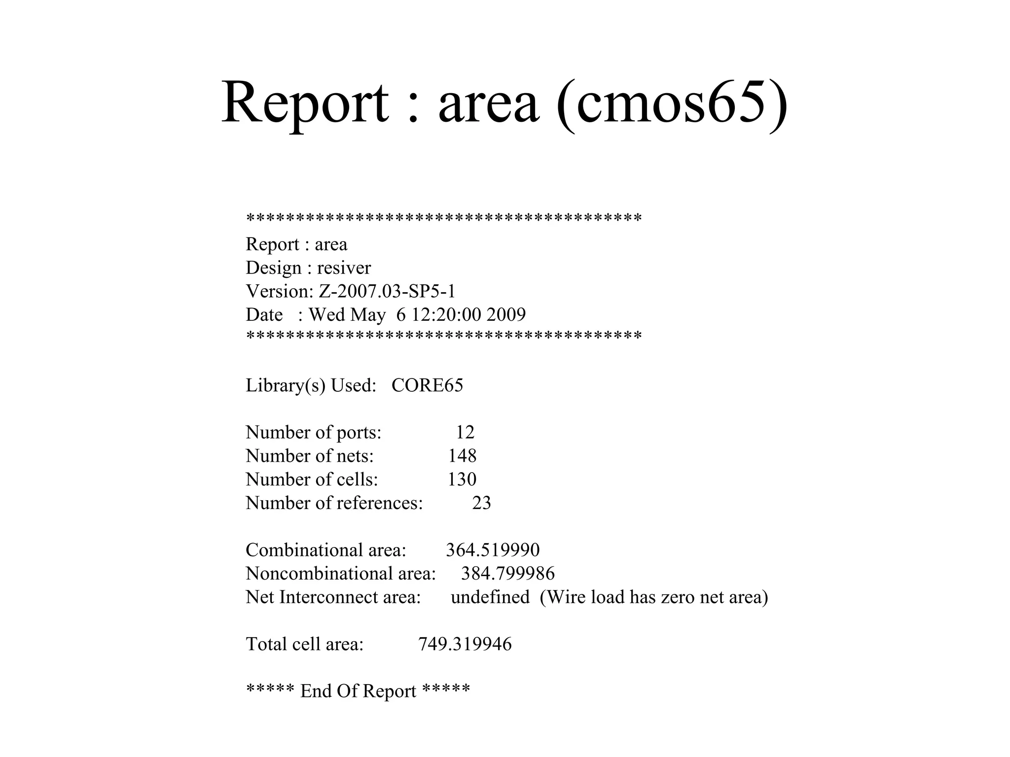
Details on area and power reports for the design, including total areas, dynamic power, and leakage power.
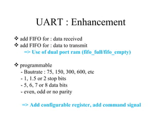
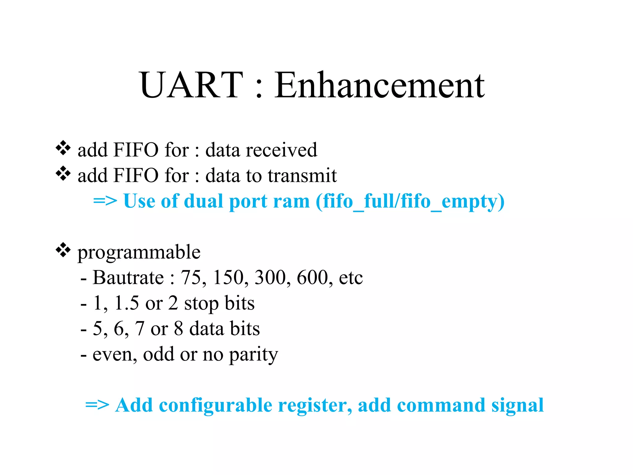
Proposed enhancements to UART with FIFO for data buffering, and features like independent registers and baud rate programming.
Description of testing FPGA functionality using PC interaction, demonstrating data transmission and reception.


