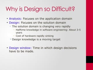
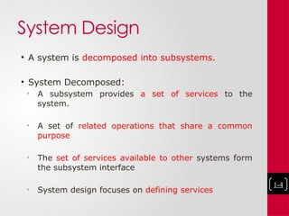
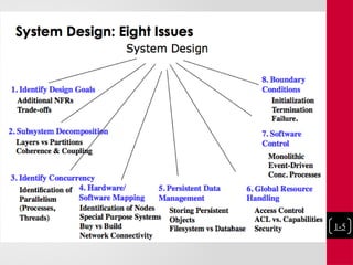
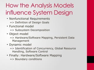
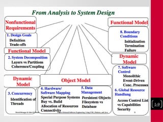
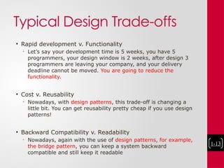
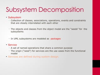
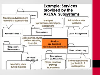
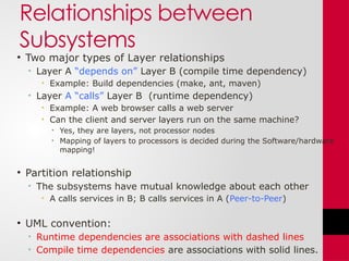
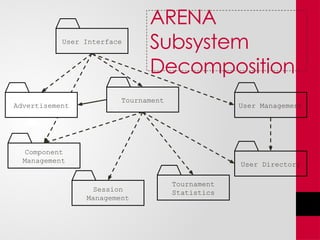
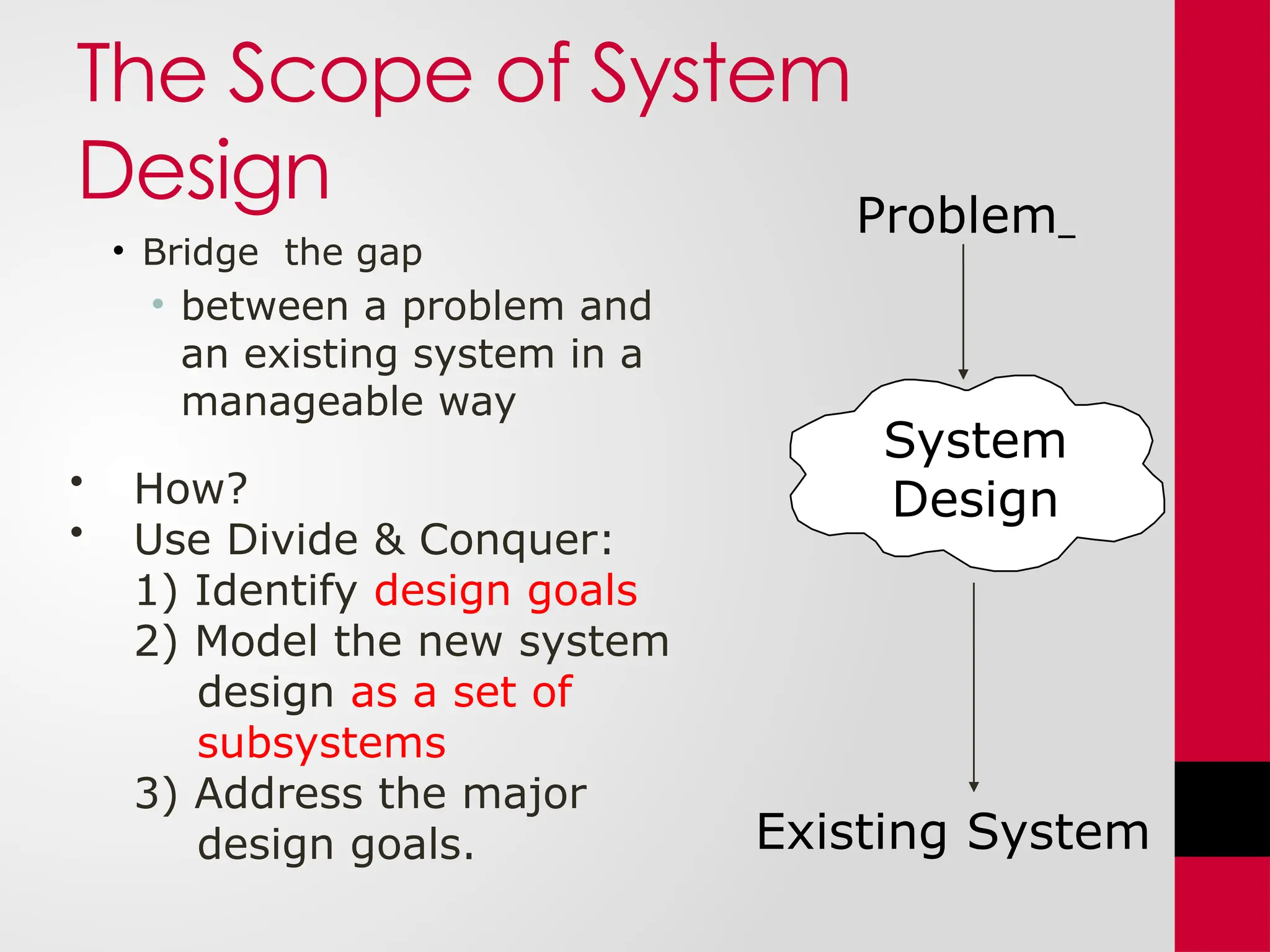
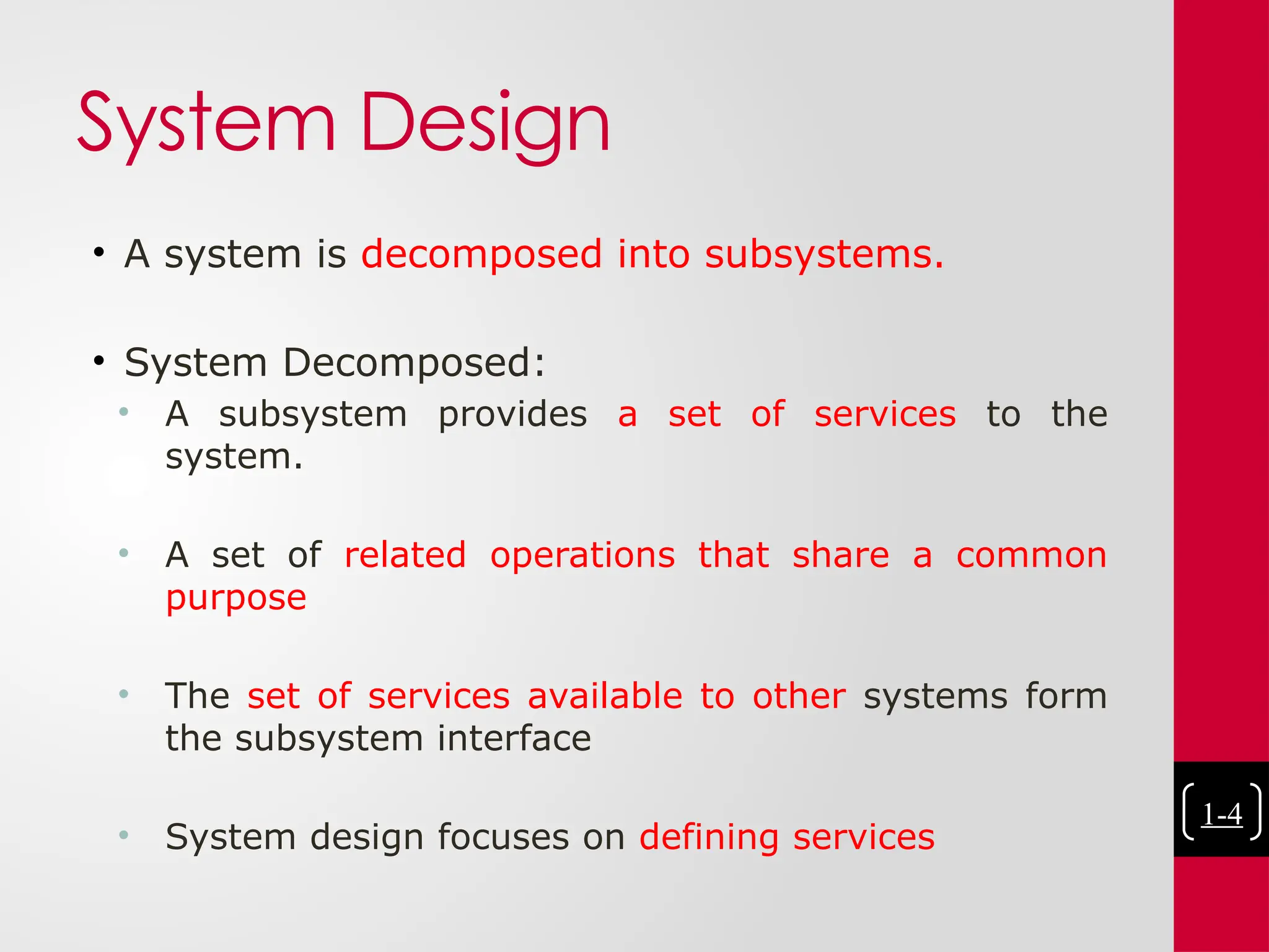
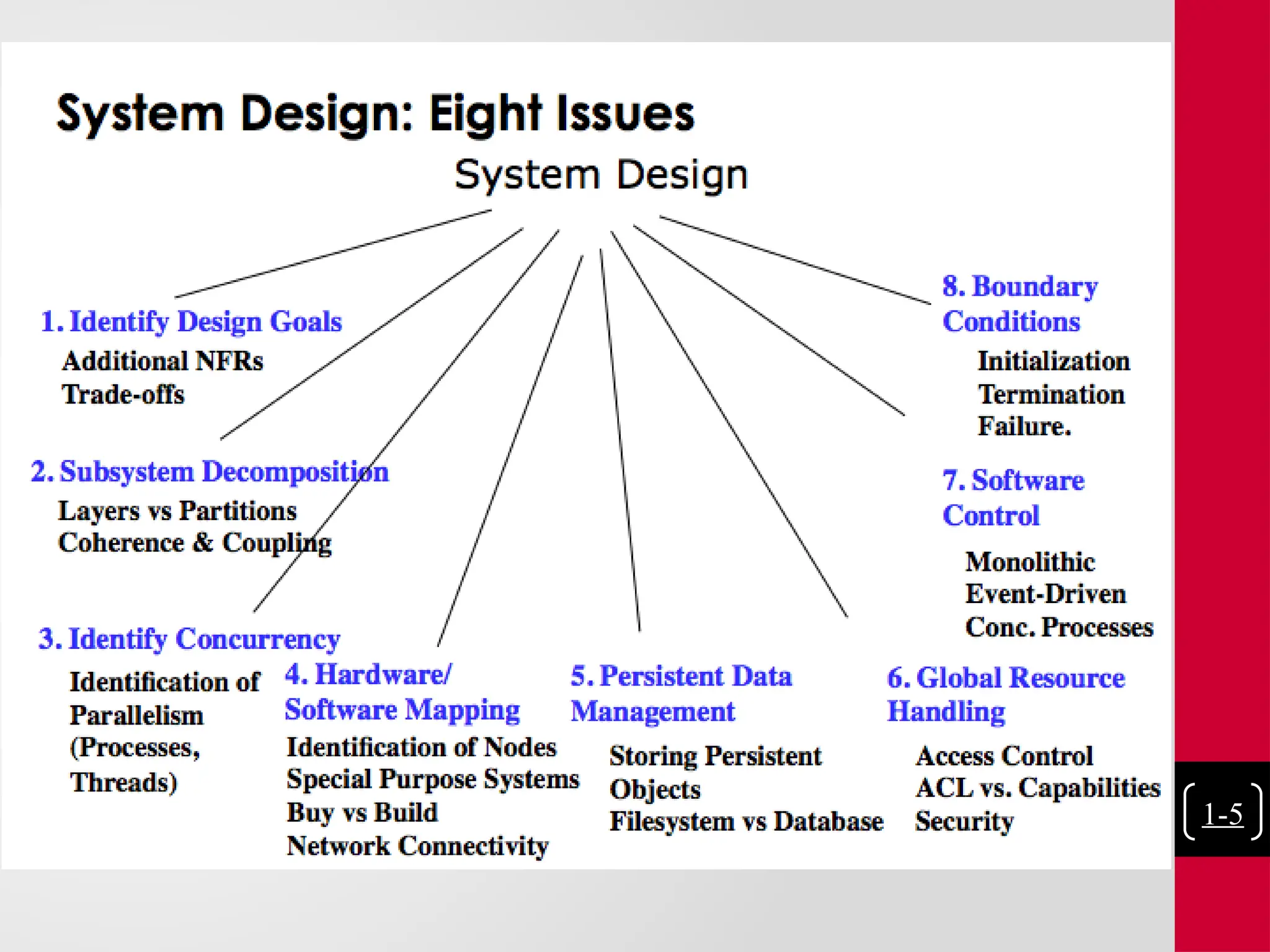
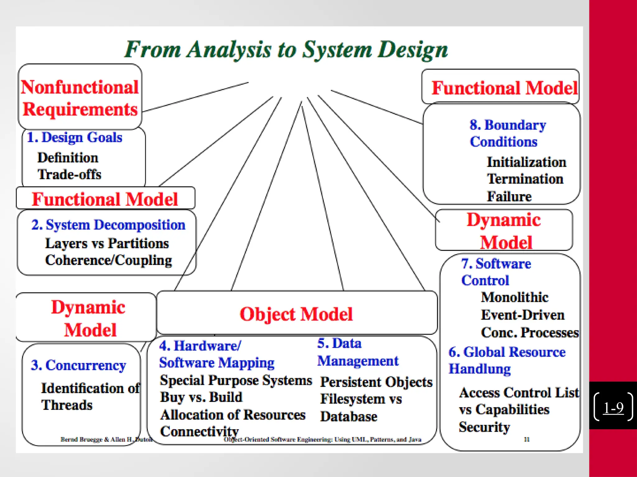
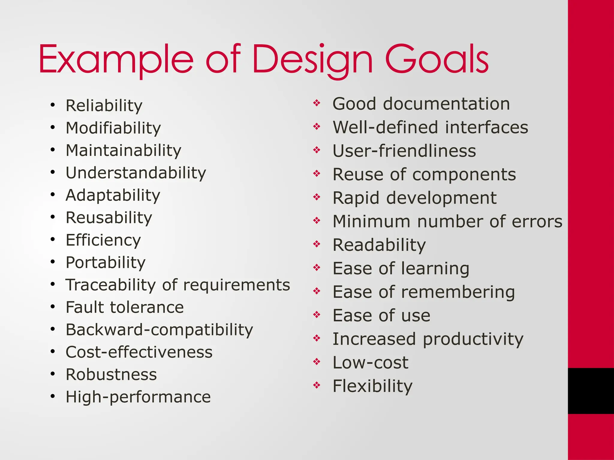
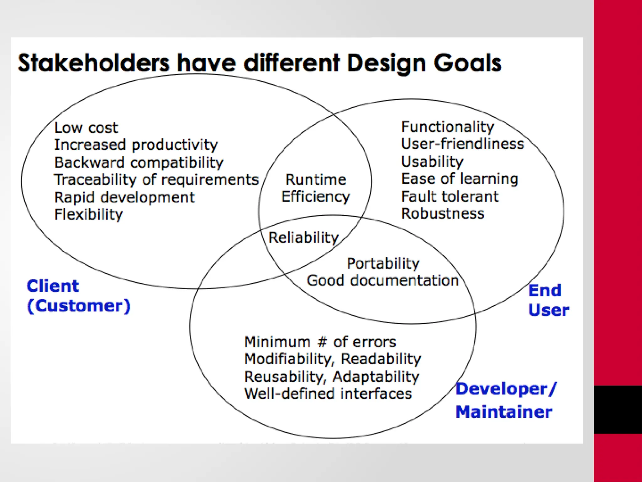
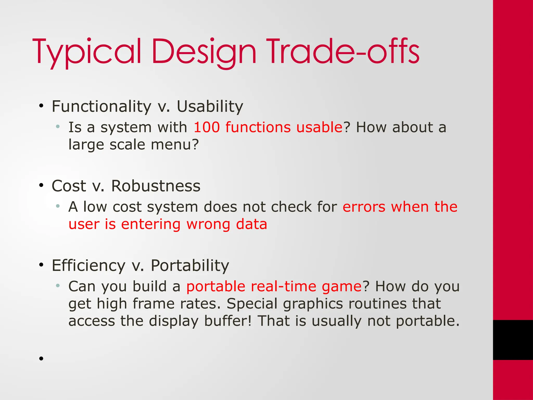
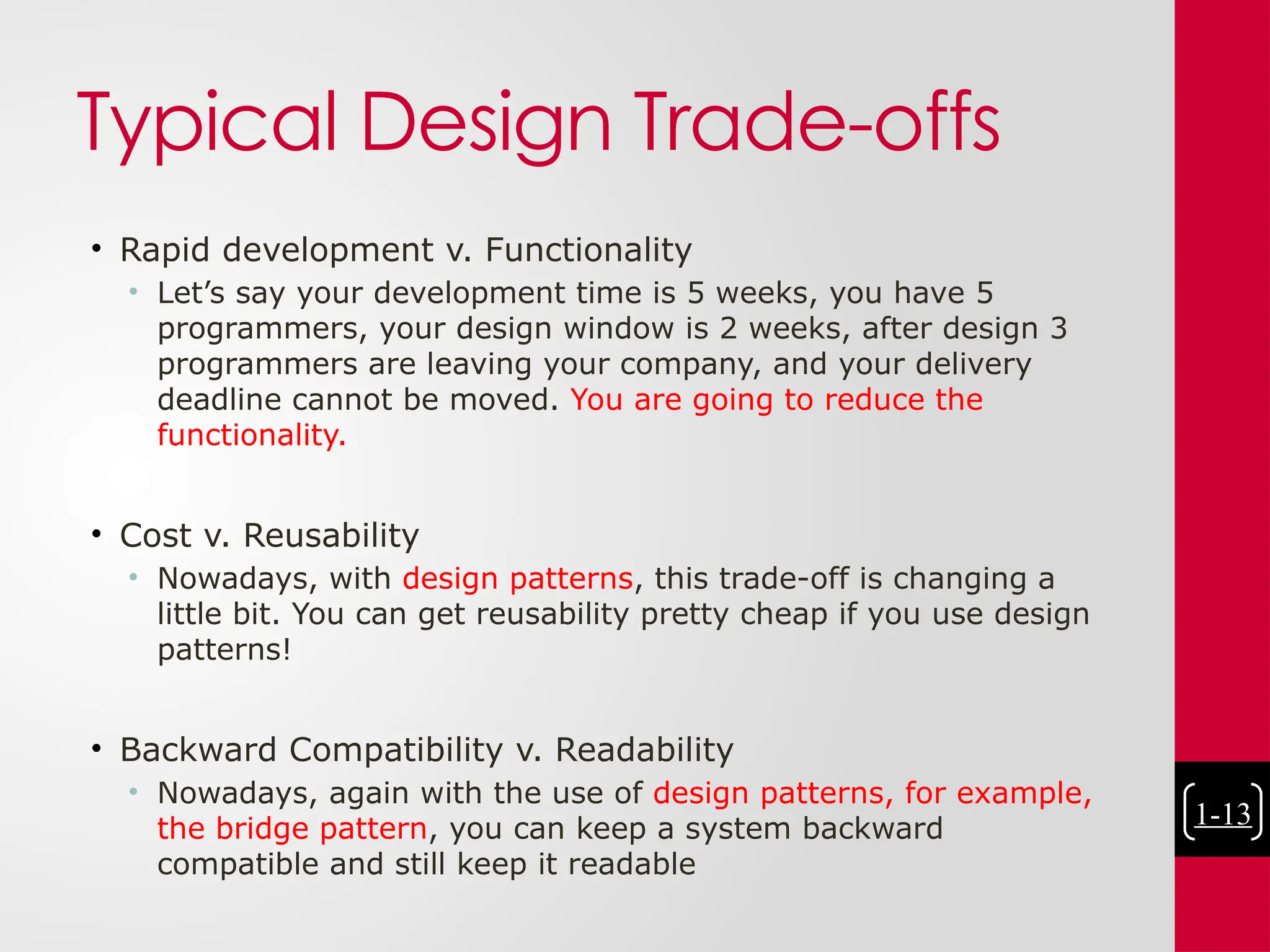
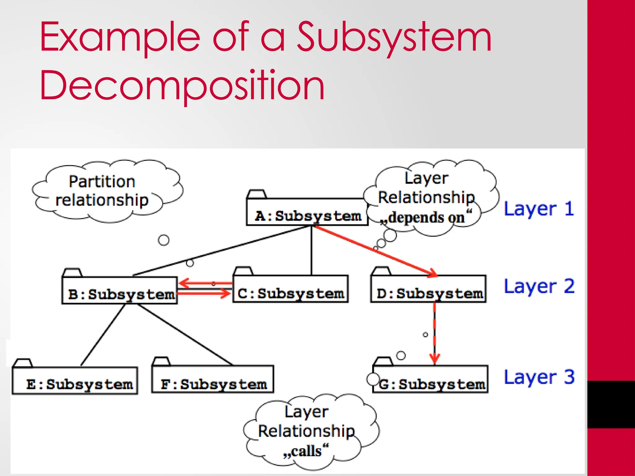
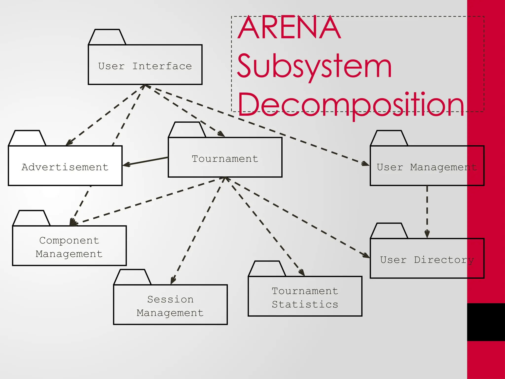
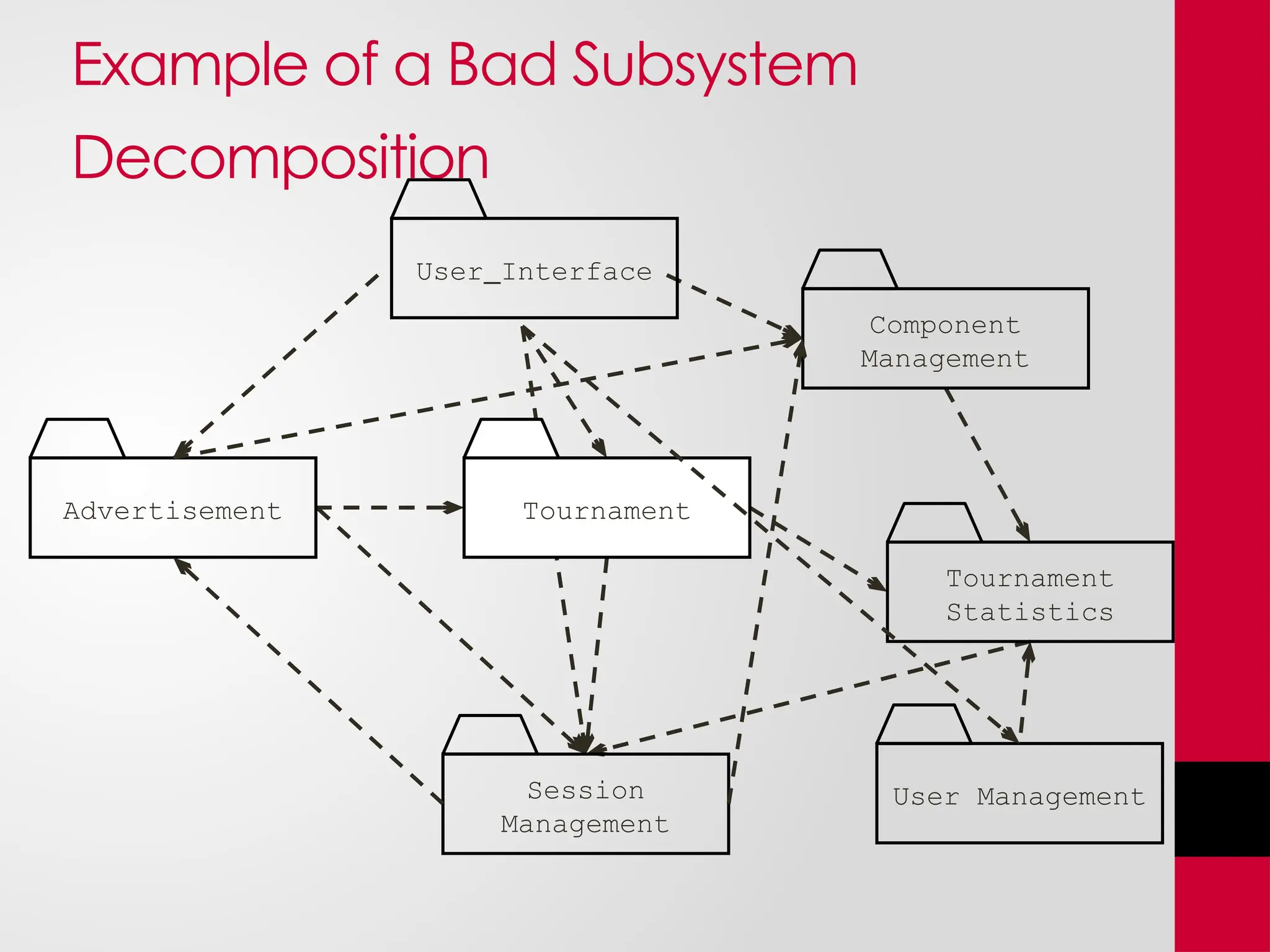
KEMBAR78
3-System Design_software_design_algo .pptx
System Design
By Dr. Maryam Kausar
Why is Design so Difficult?
• Analysis: Focuses on the application domain
• Design: Focuses on the solution domain
• The solution domain is changing very rapidly
• Halftime knowledge in software engineering: About 3-5
years
• Cost of hardware rapidly sinking
Design knowledge is a moving target
• Design window: Time in which design decisions
have to be made.
The Scope of System
Design
• Bridge the gap
• between a problem and
an existing system in a
manageable way
Problem
Existing System
System
Design
• How?
• Use Divide & Conquer:
1) Identify design goals
2) Model the new system
design as a set of
subsystems
3) Address the major
design goals.
System Design
• A system is decomposed into subsystems.
• System Decomposed:
• A subsystem provides a set of services to the
system.
• A set of related operations that share a common
purpose
• The set of services available to other systems form
the subsystem interface
• System design focuses on defining services
1-4
1-5
Activity
• System Design of Café Management System
1-6
Analysis Sources: Requirements
and System Model
1-7
How the Analysis Models
influence System Design
• Nonfunctional Requirements
=> Definition of Design Goals
• Functional model
=> Subsystem Decomposition
• Object model
=> Hardware/Software Mapping, Persistent Data
Management
• Dynamic model
=> Identification of Concurrency, Global Resource
Handling, Software Control
• Finally: Hardware/Software Mapping
=> Boundary conditions
1-9
Example of Design Goals
• Reliability
• Modifiability
• Maintainability
• Understandability
• Adaptability
• Reusability
• Efficiency
• Portability
• Traceability of requirements
• Fault tolerance
• Backward-compatibility
• Cost-effectiveness
• Robustness
• High-performance
 Good documentation
 Well-defined interfaces
 User-friendliness
 Reuse of components
 Rapid development
 Minimum number of errors
 Readability
 Ease of learning
 Ease of remembering
 Ease of use
 Increased productivity
 Low-cost
 Flexibility
Typical Design Trade-offs
• Functionality v. Usability
• Is a system with 100 functions usable? How about a
large scale menu?
• Cost v. Robustness
• A low cost system does not check for errors when the
user is entering wrong data
• Efficiency v. Portability
• Can you build a portable real-time game? How do you
get high frame rates. Special graphics routines that
access the display buffer! That is usually not portable.
•
Typical Design Trade-offs
• Rapid development v. Functionality
• Let’s say your development time is 5 weeks, you have 5
programmers, your design window is 2 weeks, after design 3
programmers are leaving your company, and your delivery
deadline cannot be moved. You are going to reduce the
functionality.
• Cost v. Reusability
• Nowadays, with design patterns, this trade-off is changing a
little bit. You can get reusability pretty cheap if you use design
patterns!
• Backward Compatibility v. Readability
• Nowadays, again with the use of design patterns, for example,
the bridge pattern, you can keep a system backward
compatible and still keep it readable
1-13
Subsystem Decomposition
• Subsystem
• Collection of classes, associations, operations, events and constraints
that are closely interrelated with each other
• The objects and classes from the object model are the “seeds” for the
subsystems
• In UML subsystems are modeled as packages
• Service
• A set of named operations that share a common purpose
• The origin (“seed”) for services are the use cases from the functional
model
• Services are defined during system design.
Properties of Subsystems:
Layers and Partitions
• A layer is a subsystem that provides a service to
another subsystem with the following restrictions:
• A layer only depends on services from lower layers
• A layer has no knowledge of higher layers
• A layer can be divided horizontally into several
independent subsystems called partitions
• Partitions provide services to other partitions on the
same layer
• Partitions are also called “weakly coupled” subsystems.
Relationships between
Subsystems
• Two major types of Layer relationships
• Layer A “depends on” Layer B (compile time dependency)
• Example: Build dependencies (make, ant, maven)
• Layer A “calls” Layer B (runtime dependency)
• Example: A web browser calls a web server
• Can the client and server layers run on the same machine?
• Yes, they are layers, not processor nodes
• Mapping of layers to processors is decided during the Software/hardware
mapping!
• Partition relationship
• The subsystems have mutual knowledge about each other
• A calls services in B; B calls services in A (Peer-to-Peer)
• UML convention:
• Runtime dependencies are associations with dashed lines
• Compile time dependencies are associations with solid lines.
Example of a Subsystem
Decomposition
Tournament
Component
Management
User Management
Tournament
Statistics
User Directory
User Interface
Session
Management
Advertisement
ARENA
Subsystem
Decomposition
Example of a Bad Subsystem
Decomposition
Advertisement
User Interface
Session
Management
User Management
Tournament
Statistics
Component
Management
Tournament
Activity
• Make Subsystem diagram for Café Management System.
1-21
Project
• Group 1: Abstract Factory, Adaptor, Bridge, Chain of Responsibility
• Group 2: Builder, Composite, Decorator, Interpreter
• Group 3: Factory Method, Façade, Flyweight, Mediator
• Group 4: Prototype ,Proxy, Observer, State
• Group 5: Singleton, Strategy, Template Method, Interpreter
• Group 6: Abstract Factory, Adaptor, Iterator, Command
• Group 7: Builder, Composite, Memento, Visitor
• Group 8: Prototype ,Proxy, Template Method , State
• Group 9: Singleton, Strategy, Bridge, Chain of Responsibility
• Group 10: Factory Method, Proxy, Template Method, Mediator
• Group 11: Builder, Adaptor, Observer ,Flyweight
• Group 12: Composite, Decorator, Iterator, Command
• Group 13: Façade, Flyweight, Proxy, Command
• Group 14: Builder, Strategy, Adaptor, Chain of Responsibility
• Group 15: Abstract Factory, Factory Method, Iterator, Command

3-System Design_software_design_algo .pptx

  • 1.
    System Design By Dr.Maryam Kausar
  • 2.
    Why is Designso Difficult? • Analysis: Focuses on the application domain • Design: Focuses on the solution domain • The solution domain is changing very rapidly • Halftime knowledge in software engineering: About 3-5 years • Cost of hardware rapidly sinking Design knowledge is a moving target • Design window: Time in which design decisions have to be made.
  • 3.
    The Scope ofSystem Design • Bridge the gap • between a problem and an existing system in a manageable way Problem Existing System System Design • How? • Use Divide & Conquer: 1) Identify design goals 2) Model the new system design as a set of subsystems 3) Address the major design goals.
  • 4.
    System Design • Asystem is decomposed into subsystems. • System Decomposed: • A subsystem provides a set of services to the system. • A set of related operations that share a common purpose • The set of services available to other systems form the subsystem interface • System design focuses on defining services 1-4
  • 5.
  • 6.
    Activity • System Designof Café Management System 1-6
  • 7.
  • 8.
    How the AnalysisModels influence System Design • Nonfunctional Requirements => Definition of Design Goals • Functional model => Subsystem Decomposition • Object model => Hardware/Software Mapping, Persistent Data Management • Dynamic model => Identification of Concurrency, Global Resource Handling, Software Control • Finally: Hardware/Software Mapping => Boundary conditions
  • 9.
  • 10.
    Example of DesignGoals • Reliability • Modifiability • Maintainability • Understandability • Adaptability • Reusability • Efficiency • Portability • Traceability of requirements • Fault tolerance • Backward-compatibility • Cost-effectiveness • Robustness • High-performance  Good documentation  Well-defined interfaces  User-friendliness  Reuse of components  Rapid development  Minimum number of errors  Readability  Ease of learning  Ease of remembering  Ease of use  Increased productivity  Low-cost  Flexibility
  • 12.
    Typical Design Trade-offs •Functionality v. Usability • Is a system with 100 functions usable? How about a large scale menu? • Cost v. Robustness • A low cost system does not check for errors when the user is entering wrong data • Efficiency v. Portability • Can you build a portable real-time game? How do you get high frame rates. Special graphics routines that access the display buffer! That is usually not portable. •
  • 13.
    Typical Design Trade-offs •Rapid development v. Functionality • Let’s say your development time is 5 weeks, you have 5 programmers, your design window is 2 weeks, after design 3 programmers are leaving your company, and your delivery deadline cannot be moved. You are going to reduce the functionality. • Cost v. Reusability • Nowadays, with design patterns, this trade-off is changing a little bit. You can get reusability pretty cheap if you use design patterns! • Backward Compatibility v. Readability • Nowadays, again with the use of design patterns, for example, the bridge pattern, you can keep a system backward compatible and still keep it readable 1-13
  • 14.
    Subsystem Decomposition • Subsystem •Collection of classes, associations, operations, events and constraints that are closely interrelated with each other • The objects and classes from the object model are the “seeds” for the subsystems • In UML subsystems are modeled as packages • Service • A set of named operations that share a common purpose • The origin (“seed”) for services are the use cases from the functional model • Services are defined during system design.
  • 16.
    Properties of Subsystems: Layersand Partitions • A layer is a subsystem that provides a service to another subsystem with the following restrictions: • A layer only depends on services from lower layers • A layer has no knowledge of higher layers • A layer can be divided horizontally into several independent subsystems called partitions • Partitions provide services to other partitions on the same layer • Partitions are also called “weakly coupled” subsystems.
  • 17.
    Relationships between Subsystems • Twomajor types of Layer relationships • Layer A “depends on” Layer B (compile time dependency) • Example: Build dependencies (make, ant, maven) • Layer A “calls” Layer B (runtime dependency) • Example: A web browser calls a web server • Can the client and server layers run on the same machine? • Yes, they are layers, not processor nodes • Mapping of layers to processors is decided during the Software/hardware mapping! • Partition relationship • The subsystems have mutual knowledge about each other • A calls services in B; B calls services in A (Peer-to-Peer) • UML convention: • Runtime dependencies are associations with dashed lines • Compile time dependencies are associations with solid lines.
  • 18.
    Example of aSubsystem Decomposition
  • 19.
    Tournament Component Management User Management Tournament Statistics User Directory UserInterface Session Management Advertisement ARENA Subsystem Decomposition
  • 20.
    Example of aBad Subsystem Decomposition Advertisement User Interface Session Management User Management Tournament Statistics Component Management Tournament
  • 21.
    Activity • Make Subsystemdiagram for Café Management System. 1-21
  • 22.
    Project • Group 1:Abstract Factory, Adaptor, Bridge, Chain of Responsibility • Group 2: Builder, Composite, Decorator, Interpreter • Group 3: Factory Method, Façade, Flyweight, Mediator • Group 4: Prototype ,Proxy, Observer, State • Group 5: Singleton, Strategy, Template Method, Interpreter • Group 6: Abstract Factory, Adaptor, Iterator, Command • Group 7: Builder, Composite, Memento, Visitor • Group 8: Prototype ,Proxy, Template Method , State • Group 9: Singleton, Strategy, Bridge, Chain of Responsibility • Group 10: Factory Method, Proxy, Template Method, Mediator • Group 11: Builder, Adaptor, Observer ,Flyweight • Group 12: Composite, Decorator, Iterator, Command • Group 13: Façade, Flyweight, Proxy, Command • Group 14: Builder, Strategy, Adaptor, Chain of Responsibility • Group 15: Abstract Factory, Factory Method, Iterator, Command

Editor's Notes

  • #2 What I teach today will be out of date in 3 years
  • #8 In Requirements analysis we have beautifully built 3 descriptions of the problem, the models. Where do the models go in system design? The above list of system design issues looks a little bit random. But there is a reason behind it: Nonfunctional Requirements => Definition of Design Goals Functional model => Subsystem Decomposition (Subsystems based on functional requirements, coherence & coupling) Object model => Hardware/software Mapping and Data Management (Persistent objects) Dynamic model => Identification of Concurrency, Global Resource Handling, Software Control Finally: From the Subsystem Decomposition => Boundary conditions
  • #11 Nielson Usability Engineering Rubin Task Analysis
  • #12 Example: Functionality vs usability. Is a system with 100 functions usable? How about a large scale menu? Low Cost vs Robustness: A low cost system does not check for errors when the user is entering wrong data (ebay Entry 5.00 vs 5,00). Let‘s say you bid for 5, 00 Euro In Germany 5,00 is 5 Euros, if the entry routine expects a „.“, then the „,“ might be overlooked, and you have bidden. for 500 Dollars! Efficiency vs Portability: Can you build a portable real-time game? How do you get high framerates. Special graphics routines that access the display buffer! That is usually not portable. If you write portable graphics code, say with the OpenGL, then you sometimes might not get the response times you are looking for. All special graphics code is still hand-tailored for a specific machine or graphics processor. Rapid development vs. functionality: Let’s say your development time is 5 weeks, you have 5 programmers, your design window is 2 weeks, after design 3 programmers are leaving your company, and your delivery deadline cannot be moved. You are going to reduce the functionality. Not all the use cases in your model can be implemented nor delivered. Cost vs. Reusability: This is an interesting trade-off, whose validity is changing right now. In the past, if you tried to make your design reusable you had to add extra effort. Recode your data structures (move from array of int to array of Generic). Moving from a 1-1 association to a many-many association involved more coding and more testing. Nowadays, with design patterns, this trade-off is changing a little bit. You can get reusability pretty cheap if you use design patterns! Backward Compatibility vs Readability. The same applies to this trade-off. In the past you would guarantee backward compatibility by introducing special switches. #Ifdef OldSystem then WriteToPaperTapeWriter #Ifdef Newsystems then WritetoCD-R Nowadays, again with the use of design patterns, for example, the bridge pattern, you can keep a system backward compatibile and still keep it readable!
  • #14 Relation of subsystems to each other is similar to object model System topology is similar functional model! A service is a group of operations provided by the subsystem Services are defined during system design and refined as subsystem interfaces during object design.
  • #16 A large system should be decomposed into subsystems using both, layers and partitions Layering and partitioning are techniques to achieve low coupling!!! In an object-oriented design, each subsystem makes its layer a subclass of the generic layer class provided by the UI subsystem. In JEWEL, each individual subsystem provides its own zoom and refresh methods. Ideally the refresh method will be called for every draw operation. The UI subsystem is responsible for knowing when to call for a refresh (but the UI group will not have to implement it itself: it is a callback method implemented by the visualization and GIS group). All the interfaces with UI (such as how UI will provide the other groups with selection information) should be well documented and agreed on by all groups.
  • #17 Example: Peer-to-Peer systems
  • #18 Subsystem Decomposition Heuristics - No more than 7+/-2 subsystems More subsystems increase coherence but also complexity (more services) - No more than 4+/-2 layers Good design: Try to find 3 layers!!!! In many cases this is possible. 3-tier-architectures are an example
  • #19 New type of association: The dashed line means “depends on at runtime”. The solid line means “depends on at compile time”.
  • #20 Why is this decomposition bad? It has high coupling, almost every subsystem relies on every other subsystem. Too much “ravioli”…..!