Download to read offline
![3/4/2019
3
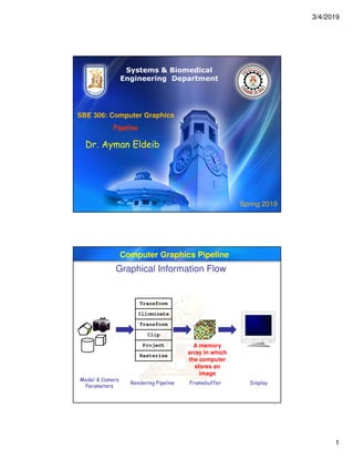
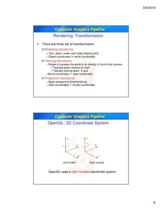
Computer Graphics Pipeline
Spring 2011
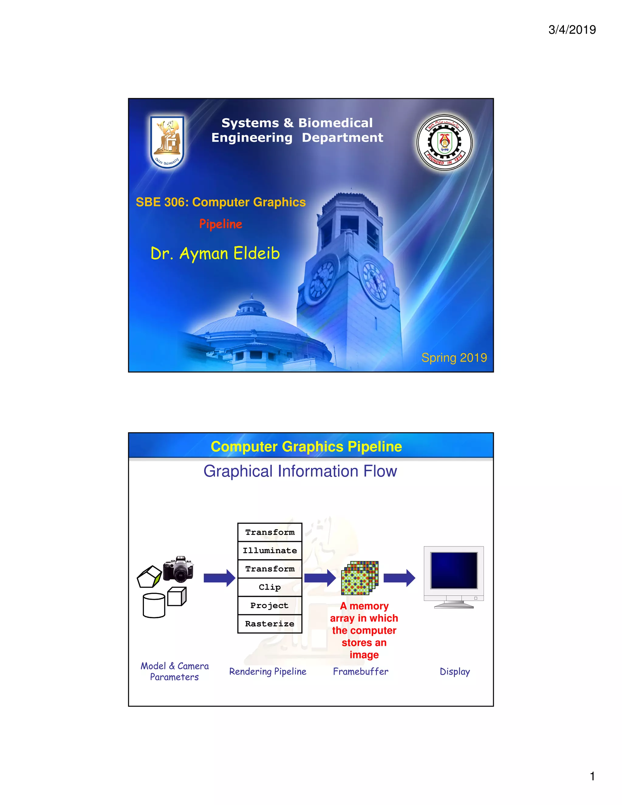
Modeling
Transforms
3D geometry
Primitives
Lighting
Calculations
Viewing
Transform
Clipping
Projection
Transform
Scan
Conversion
Image
Model/view transforms combined
Really “vertices” not “primitives”
Making this the vertex pipeline
There’s a lot going on in the “scan conversion”
stage! [pixel or fragment pipeline]
Primitive assembly
Rasterization
Texture mapping
Per-pixel lighting
Visibility (Z-buffer)
For an OpenGL system
Cont.
Rendering Pipeline
Computer Graphics Pipeline
Graphical Information Flow
GPUCPU
Application
Vertex
Processor & Rasterization
Assembly
& Rasterization
Pixel
Processor
Vertices
(3D)
Vertices
(2D)
Fragments
(pre-pixels)
Final pixels
(Color, Depth)
Graphics State
Render-to-texture
Application Geometry
“vertex pipeline”
Rasterization
“pixel/fragment pipeline”
Handle input,
Simulation & AI, etc.
Transform, Lighting, Calculate
texture coords, etc.
fill pixels, Interpolate vertex
parameters, Look up/filter
textures, etc.
Video
Memory
(Textures)](https://image.slidesharecdn.com/4-pipeline-200816191833/85/4-pipeline-computer-graphics-3-320.jpg)

![3/4/2019
9
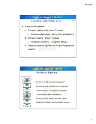
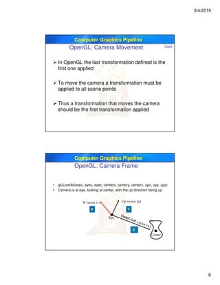
Computer Graphics Pipeline
OpenGL: Specifying Viewpoint
glMatrixMode(GL_MODELVIEW);
glLoadIdentity();
gluLookAt(eyeX, eyeY, eyeZ,
lookX, lookY, lookZ,
upX, upY, upZ);
eye[XYZ]: camera position in world coordinates
look[XYZ]: a point centered in camera’s view
up[XYZ]: a vector defining the camera’s vertical
Creates a matrix that transforms points in world coordinates to camera
coordinates
Camera at origin
Looking down -Z axis
Up vector aligned with Y axis (actually Y-Z plane)
Computer Graphics Pipeline
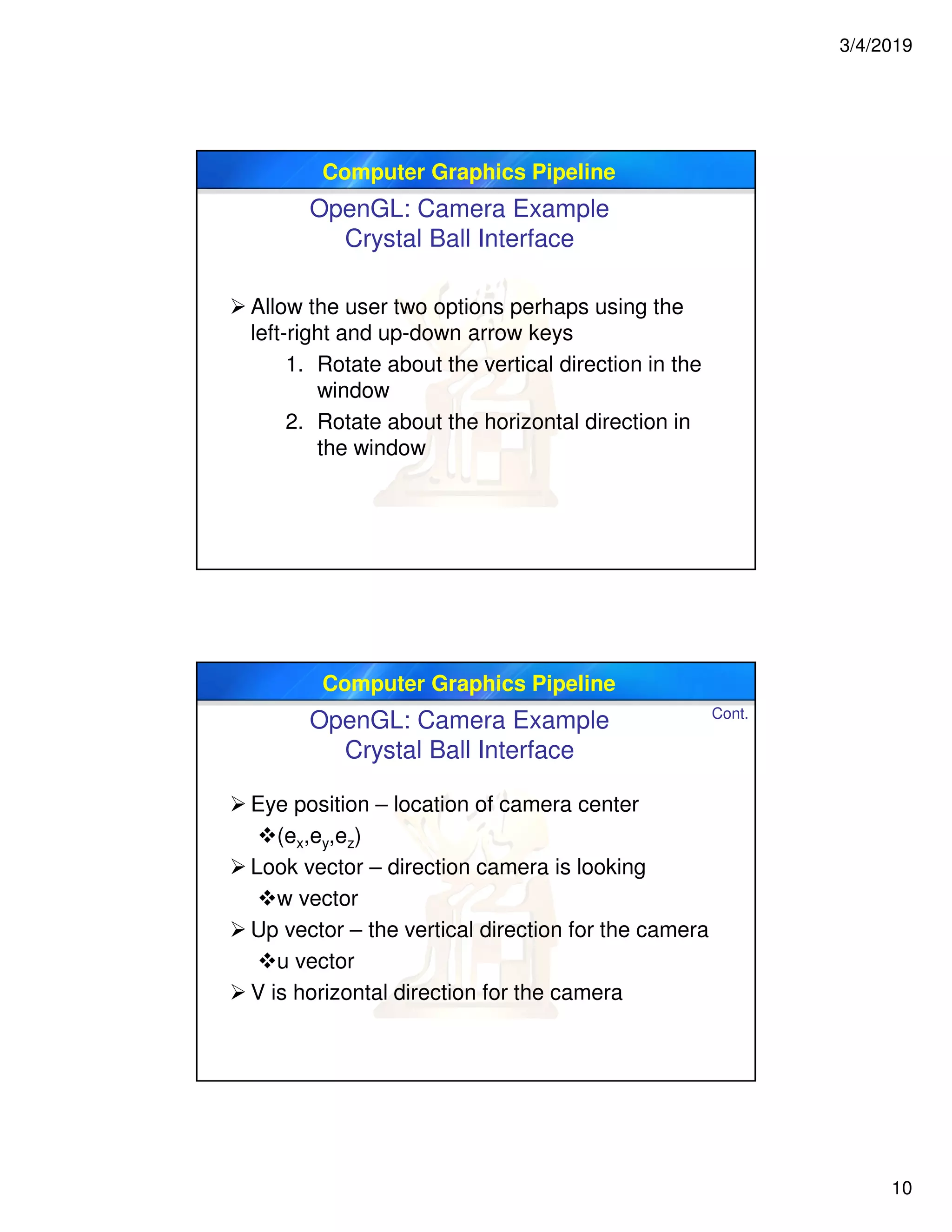
OpenGL: Camera Movement
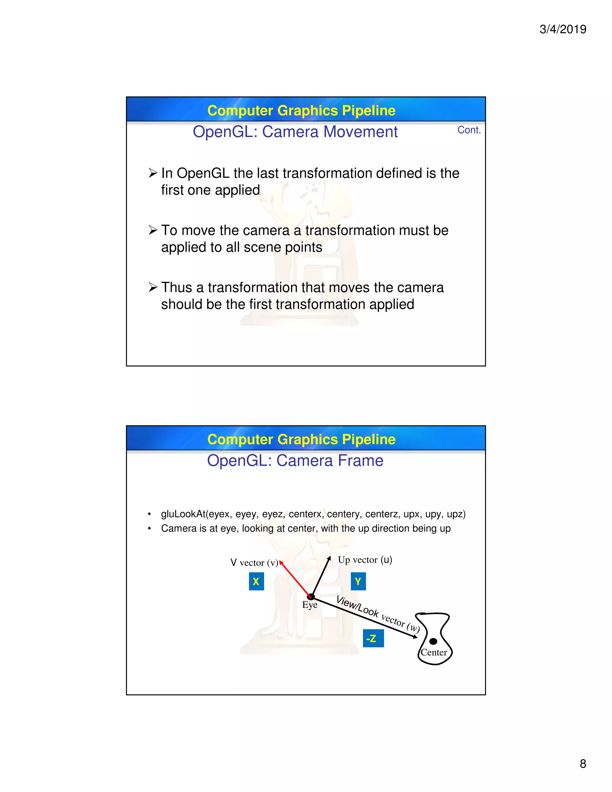
gluLookAt(eyex, eyey, eyez, centerx, centery, centerz, upx, upy, upz)
Camera is at eye, looking at center, with the up direction being up
First, create a coordinate frame for the camera
The look vector is center minus eye
Then use cross product with up vector
Define a rotation matrix
Apply appropriate translation for camera (eye)
location](https://image.slidesharecdn.com/4-pipeline-200816191833/85/4-pipeline-computer-graphics-9-320.jpg)

![3/4/2019
3
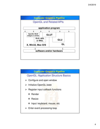
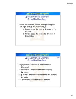
Computer Graphics Pipeline
Spring 2011
Modeling
Transforms
3D geometry
Primitives
Lighting
Calculations
Viewing
Transform
Clipping
Projection
Transform
Scan
Conversion
Image
Model/view transforms combined
Really “vertices” not “primitives”
Making this the vertex pipeline
There’s a lot going on in the “scan conversion”
stage! [pixel or fragment pipeline]
Primitive assembly
Rasterization
Texture mapping
Per-pixel lighting
Visibility (Z-buffer)
For an OpenGL system
Cont.
Rendering Pipeline
Computer Graphics Pipeline
Graphical Information Flow
GPUCPU
Application
Vertex
Processor & Rasterization
Assembly
& Rasterization
Pixel
Processor
Vertices
(3D)
Vertices
(2D)
Fragments
(pre-pixels)
Final pixels
(Color, Depth)
Graphics State
Render-to-texture
Application Geometry
“vertex pipeline”
Rasterization
“pixel/fragment pipeline”
Handle input,
Simulation & AI, etc.
Transform, Lighting, Calculate
texture coords, etc.
fill pixels, Interpolate vertex
parameters, Look up/filter
textures, etc.
Video
Memory
(Textures)](https://image.slidesharecdn.com/4-pipeline-200816191833/75/4-pipeline-computer-graphics-3-2048.jpg)


![3/4/2019
9
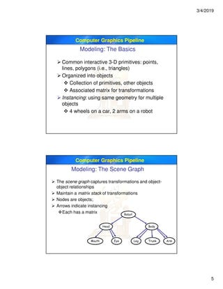
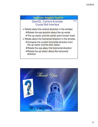
Computer Graphics Pipeline
OpenGL: Specifying Viewpoint
glMatrixMode(GL_MODELVIEW);
glLoadIdentity();
gluLookAt(eyeX, eyeY, eyeZ,
lookX, lookY, lookZ,
upX, upY, upZ);
eye[XYZ]: camera position in world coordinates
look[XYZ]: a point centered in camera’s view
up[XYZ]: a vector defining the camera’s vertical
Creates a matrix that transforms points in world coordinates to camera
coordinates
Camera at origin
Looking down -Z axis
Up vector aligned with Y axis (actually Y-Z plane)
Computer Graphics Pipeline
OpenGL: Camera Movement
gluLookAt(eyex, eyey, eyez, centerx, centery, centerz, upx, upy, upz)
Camera is at eye, looking at center, with the up direction being up
First, create a coordinate frame for the camera
The look vector is center minus eye
Then use cross product with up vector
Define a rotation matrix
Apply appropriate translation for camera (eye)
location](https://image.slidesharecdn.com/4-pipeline-200816191833/75/4-pipeline-computer-graphics-9-2048.jpg)

This document discusses the computer graphics pipeline. It describes the key stages of the pipeline including modeling, transforms, lighting calculations, viewing transforms, clipping, projection transforms, and rasterization. It also provides details on OpenGL and how it implements aspects of the graphics pipeline such as specifying the camera viewpoint using functions like gluLookAt. Finally, it gives an example of how to implement camera rotation in an OpenGL application to view a 3D scene from different angles.


