vYV lsaVj
2
•Understand theevolution and history of GSM.
Learn about GSM network architecture.
Study GSM interfaces and protocols.
Explore GSM logical and physical channels.
Understand GSM services and applications.
Overview of GSM security features.
Content
3.
vYV lsaVj
3
•GSM standsfor Global System for Mobile
Communications.
Developed by ETSI in the 1980s.
Standard for 2G digital cellular networks.
Widely used in Europe, Asia, and globally.
Offers voice, SMS, and limited data
services.
Introduction to GSM
8
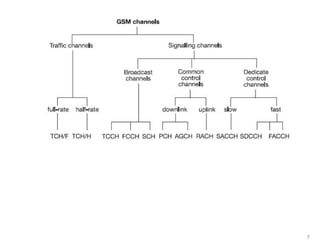
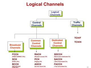
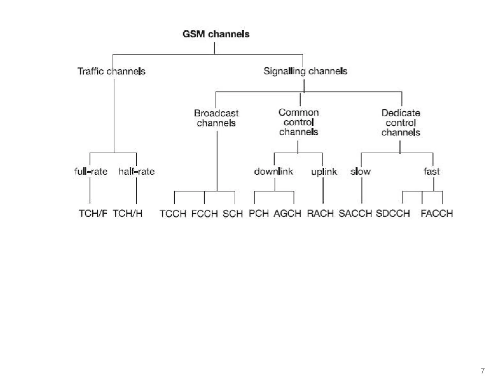
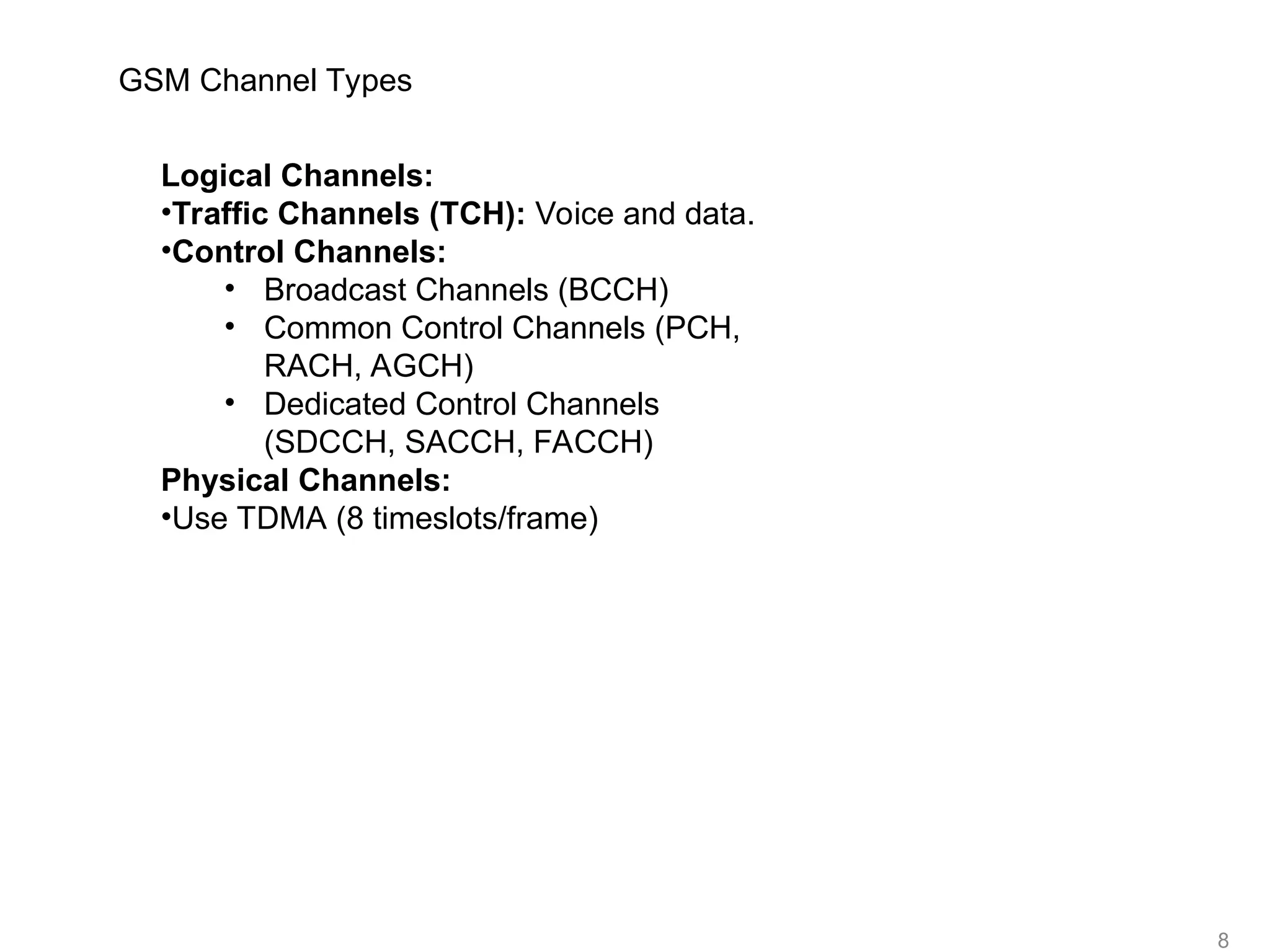
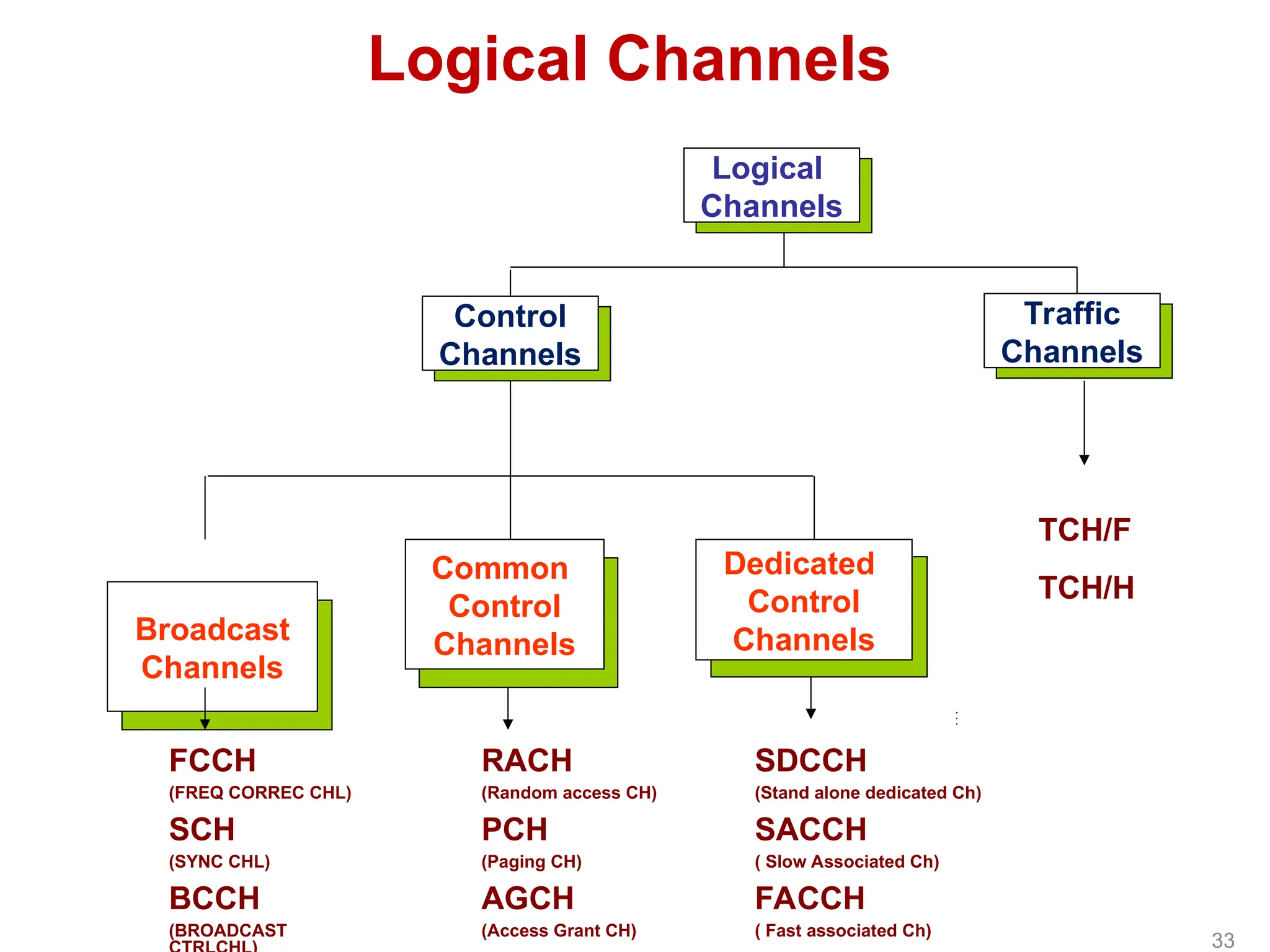
GSM Channel Types
LogicalChannels:
•Traffic Channels (TCH): Voice and data.
•Control Channels:
• Broadcast Channels (BCCH)
• Common Control Channels (PCH,
RACH, AGCH)
• Dedicated Control Channels
(SDCCH, SACCH, FACCH)
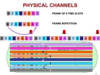
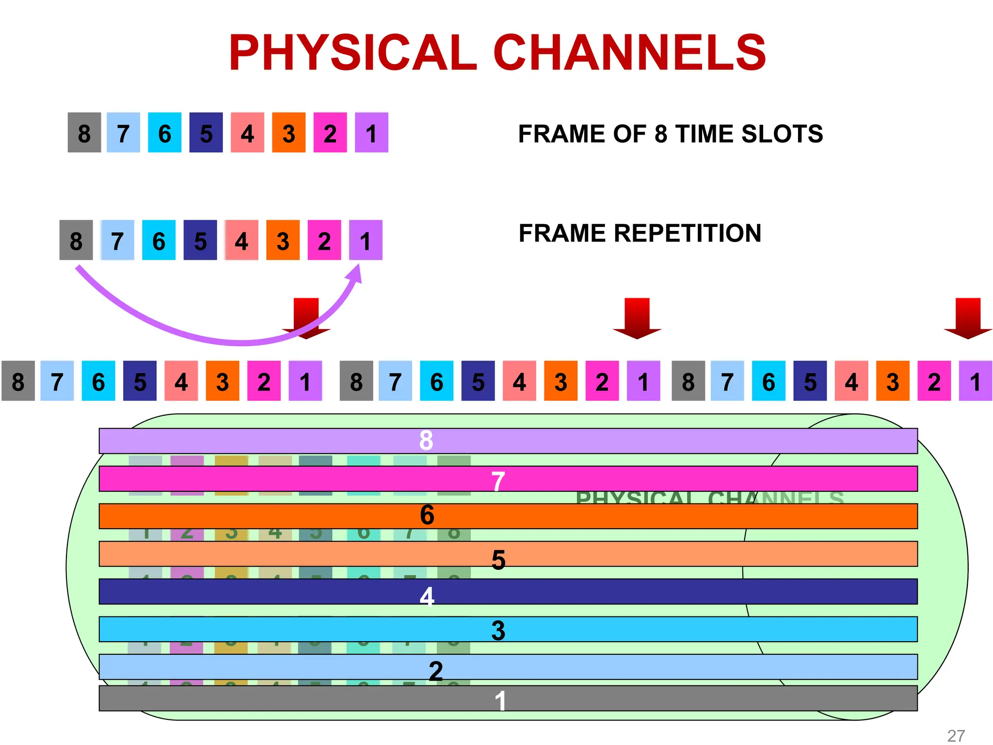
Physical Channels:
•Use TDMA (8 timeslots/frame)
9.
9
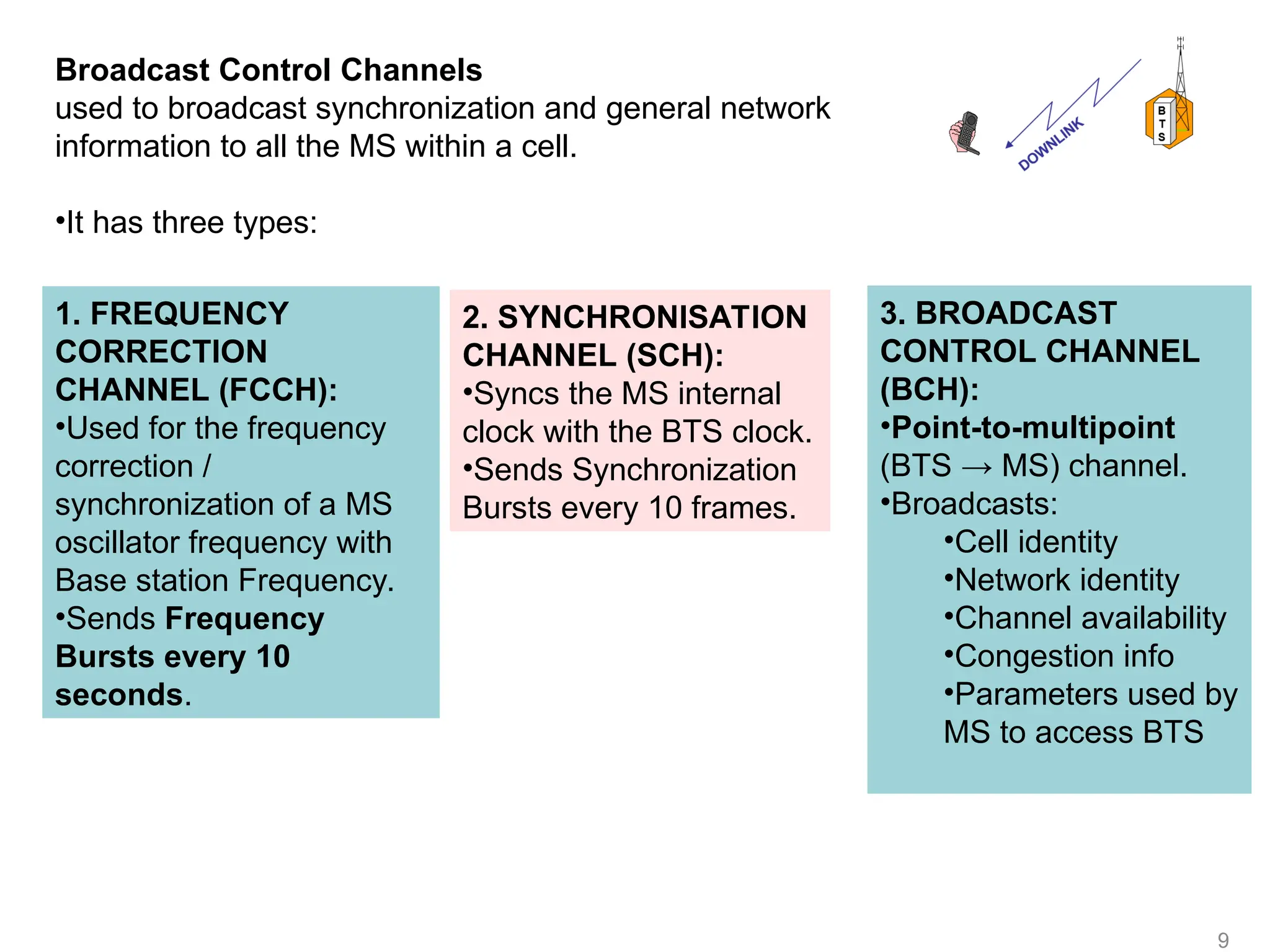
Broadcast Control Channels
usedto broadcast synchronization and general network
information to all the MS within a cell.
•It has three types:
1. FREQUENCY
CORRECTION
CHANNEL (FCCH):
•Used for the frequency
correction /
synchronization of a MS
oscillator frequency with
Base station Frequency.
•Sends Frequency
Bursts every 10
seconds.
2. SYNCHRONISATION
CHANNEL (SCH):
•Syncs the MS internal
clock with the BTS clock.
•Sends Synchronization
Bursts every 10 frames.
3. BROADCAST
CONTROL CHANNEL
(BCH):
•Point-to-multipoint
(BTS → MS) channel.
•Broadcasts:
•Cell identity
•Network identity
•Channel availability
•Congestion info
•Parameters used by
MS to access BTS
10.
10
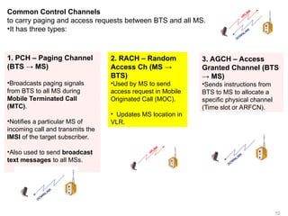
Common Control Channels
tocarry paging and access requests between BTS and all MS.
•It has three types:
1. PCH – Paging Channel
(BTS → MS)
•Broadcasts paging signals
from BTS to all MS during
Mobile Terminated Call
(MTC).
•Notifies a particular MS of
incoming call and transmits the
IMSI of the target subscriber.
•Also used to send broadcast
text messages to all MSs.
2. RACH – Random
Access Ch (MS →
BTS)
•Used by MS to send
access request in Mobile
Originated Call (MOC).
• Updates MS location in
VLR.
3. AGCH – Access
Granted Channel (BTS
→ MS)
•Sends instructions from
BTS to MS to allocate a
specific physical channel
(Time slot or ARFCN).
11.
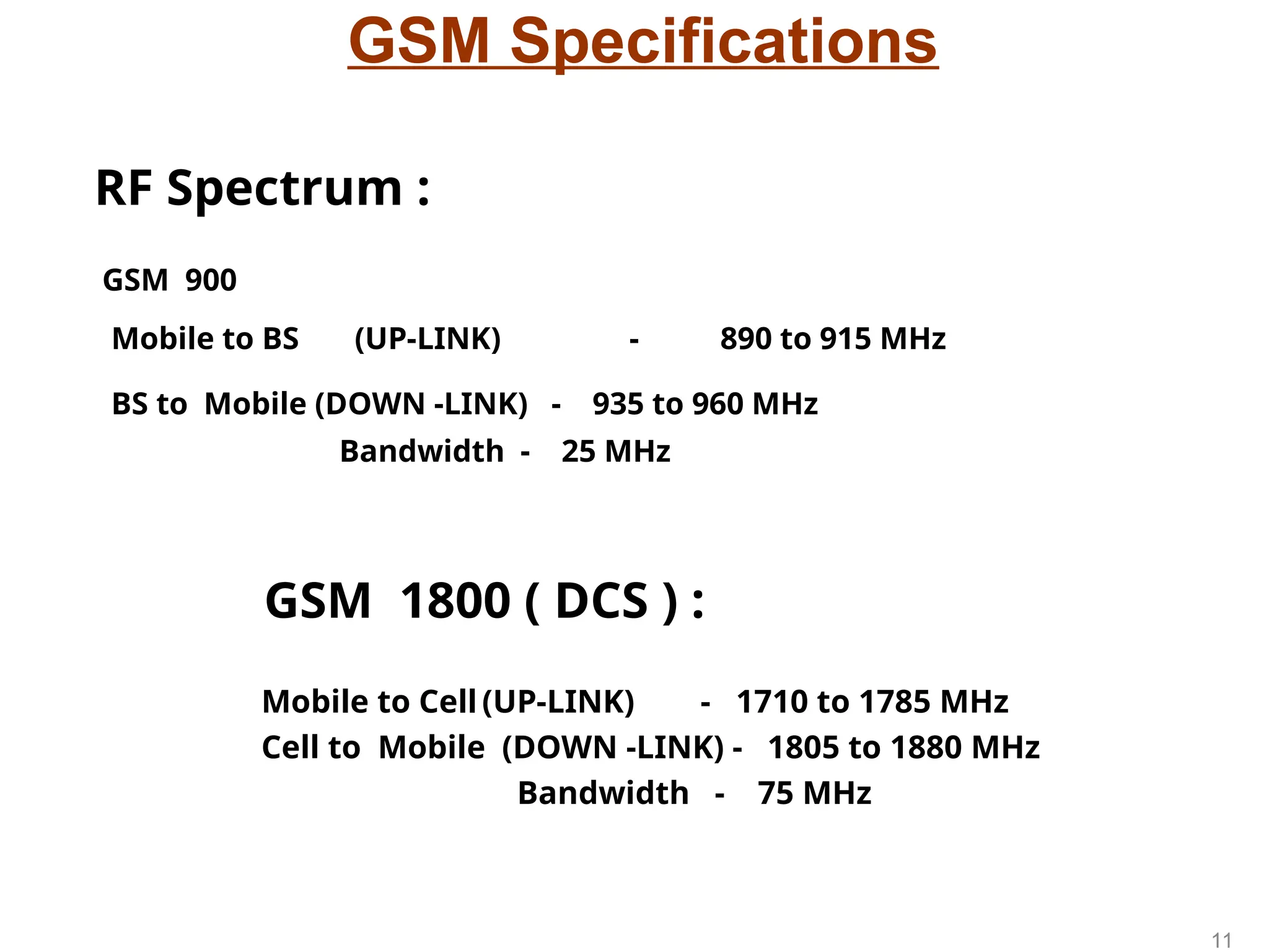
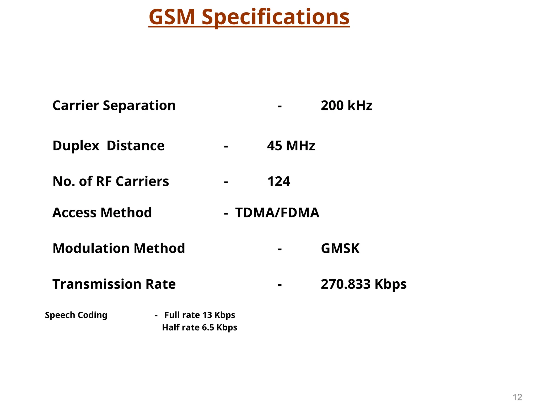
GSM Specifications
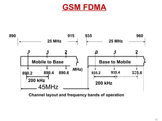
GSM 900
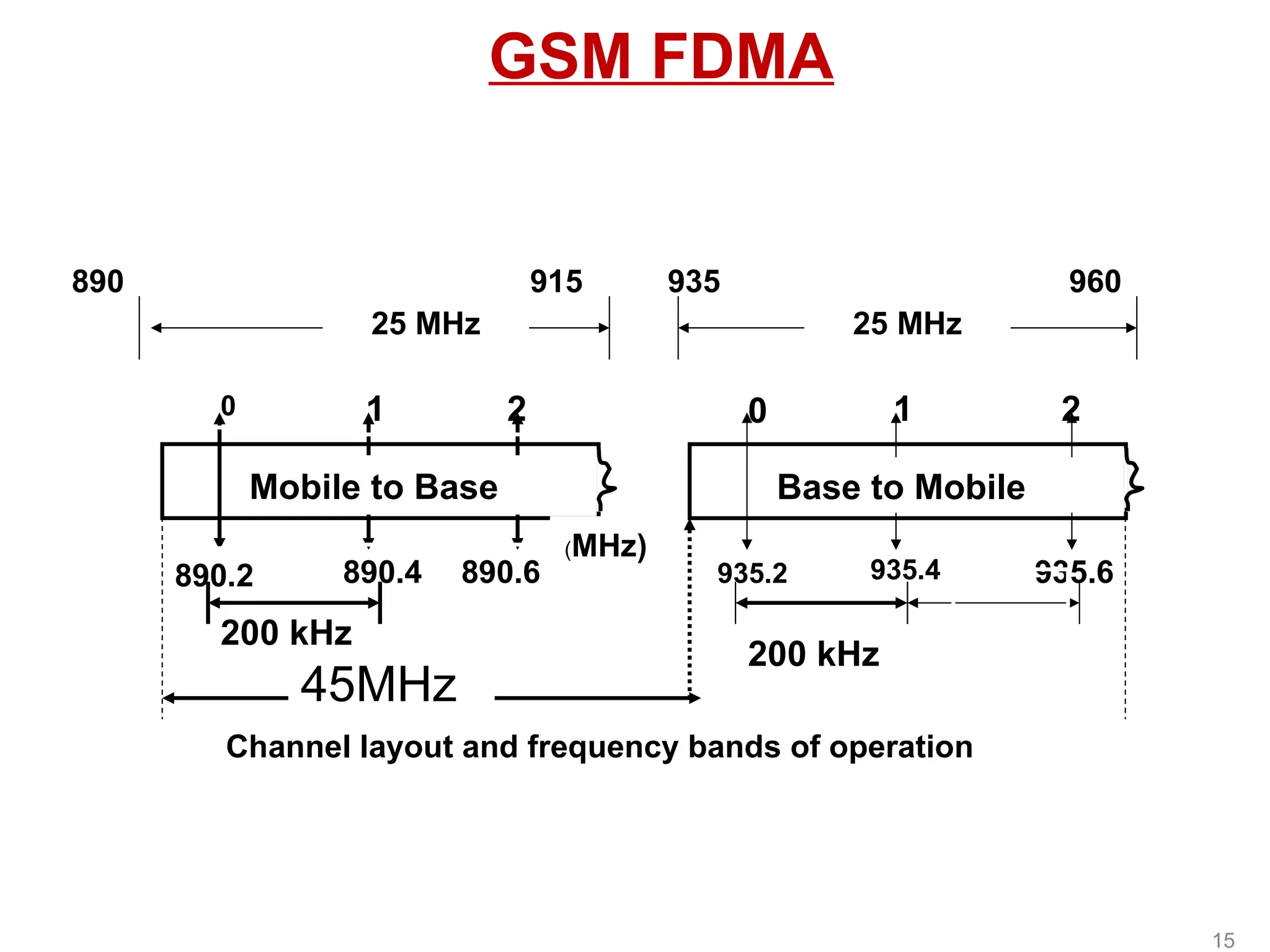
Mobileto BS (UP-LINK) - 890 to 915 MHz
BS to Mobile (DOWN -LINK) - 935 to 960 MHz
Bandwidth - 25 MHz
GSM 1800 ( DCS ) :
Mobile to Cell (UP-LINK) - 1710 to 1785 MHz
Cell to Mobile (DOWN -LINK) - 1805 to 1880 MHz
Bandwidth - 75 MHz
RF Spectrum :
11
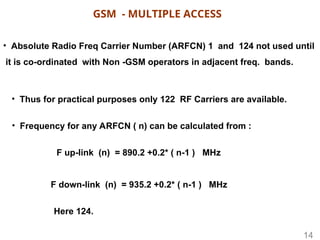
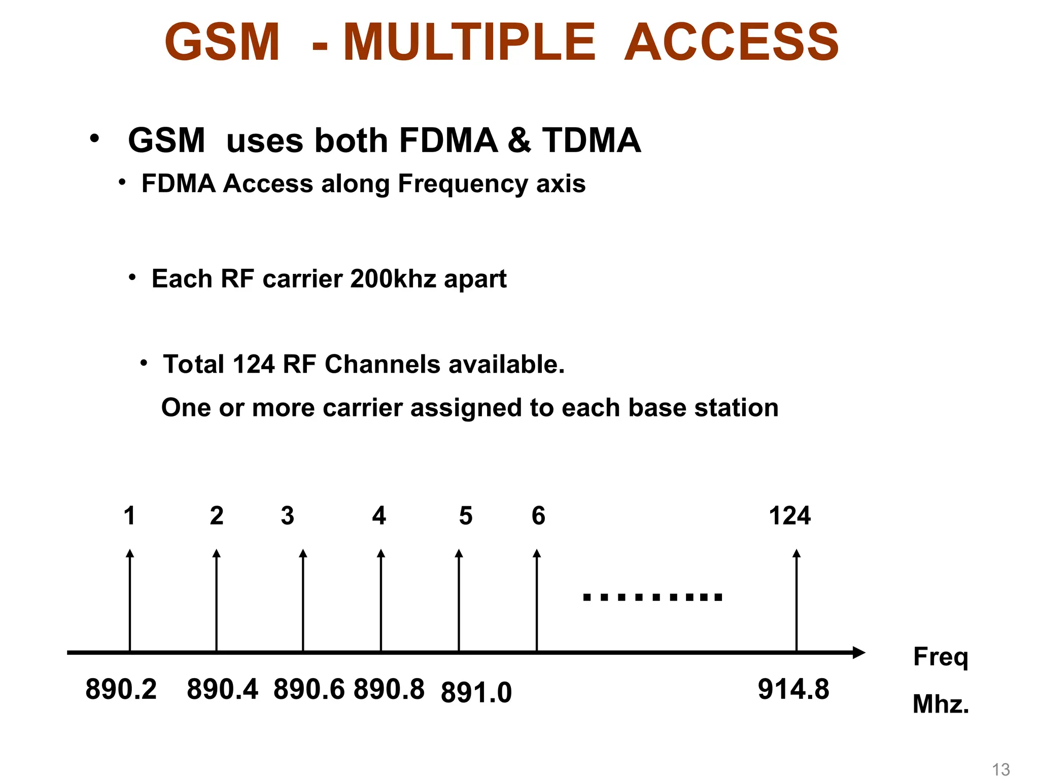
GSM - MULTIPLEACCESS
• GSM uses both FDMA & TDMA
Freq
Mhz.
890.2
1
890.4
2
890.6
3
890.8
4
891.0
5 6
914.8
124
• FDMA Access along Frequency axis
• Each RF carrier 200khz apart
• Total 124 RF Channels available.
One or more carrier assigned to each base station
……...
13
14.
• Absolute RadioFreq Carrier Number (ARFCN) 1 and 124 not used until
it is co-ordinated with Non -GSM operators in adjacent freq. bands.
• Thus for practical purposes only 122 RF Carriers are available.
F up-link (n) = 890.2 +0.2* ( n-1 ) MHz
F down-link (n) = 935.2 +0.2* ( n-1 ) MHz
• Frequency for any ARFCN ( n) can be calculated from :
Here 124.
GSM - MULTIPLE ACCESS
14
15.
GSM FDMA
25 MHz25 MHz
Mobile to Base
0 1 2
890.2 890.4 890.6
(MHz)
Base to Mobile
0 1 2
935.2 935.4 935.6
200 kHz
45MHz
Channel layout and frequency bands of operation
890 935 960
915
200 kHz
15
16.
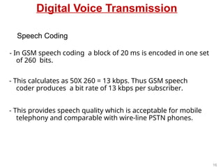
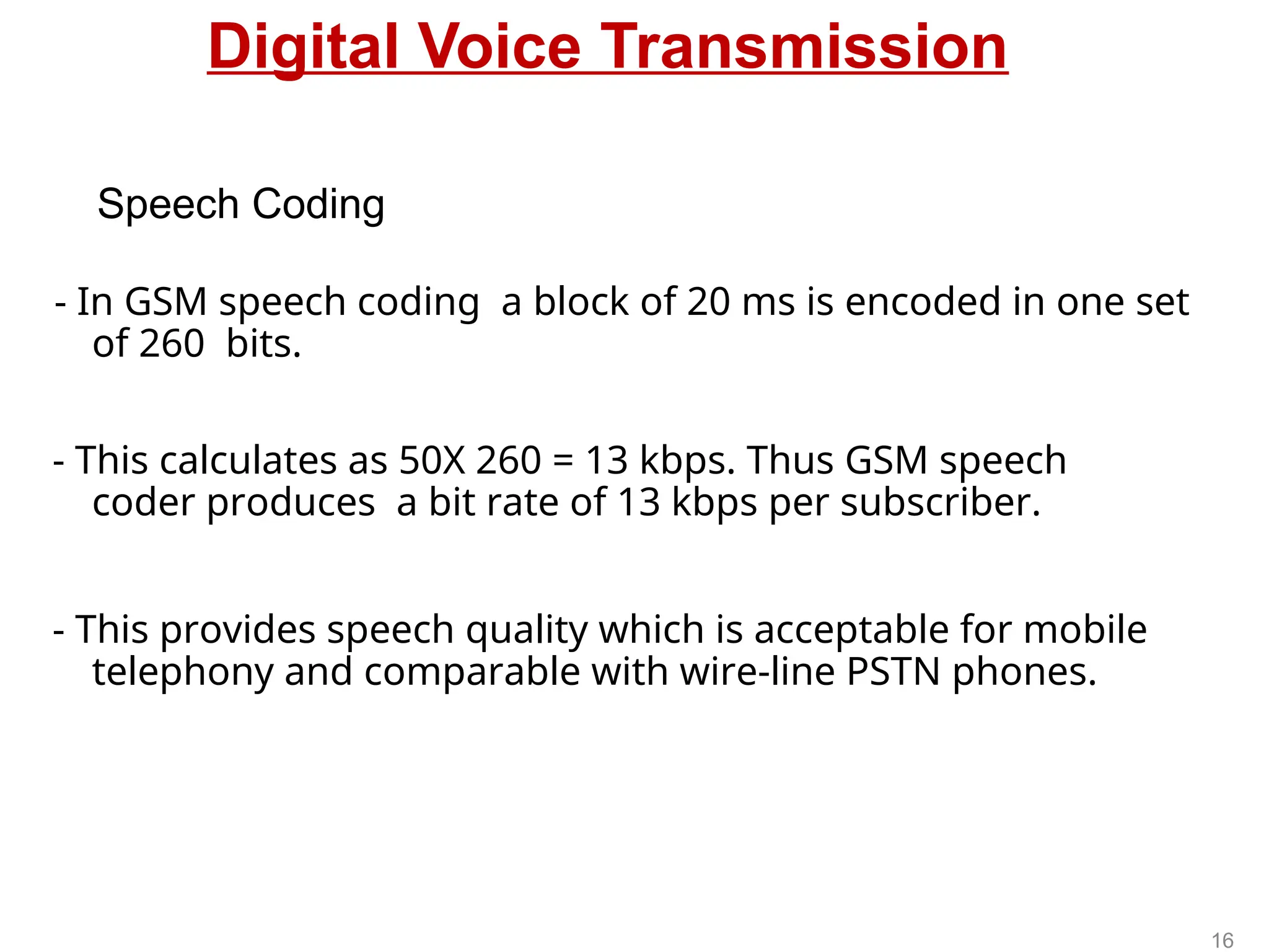
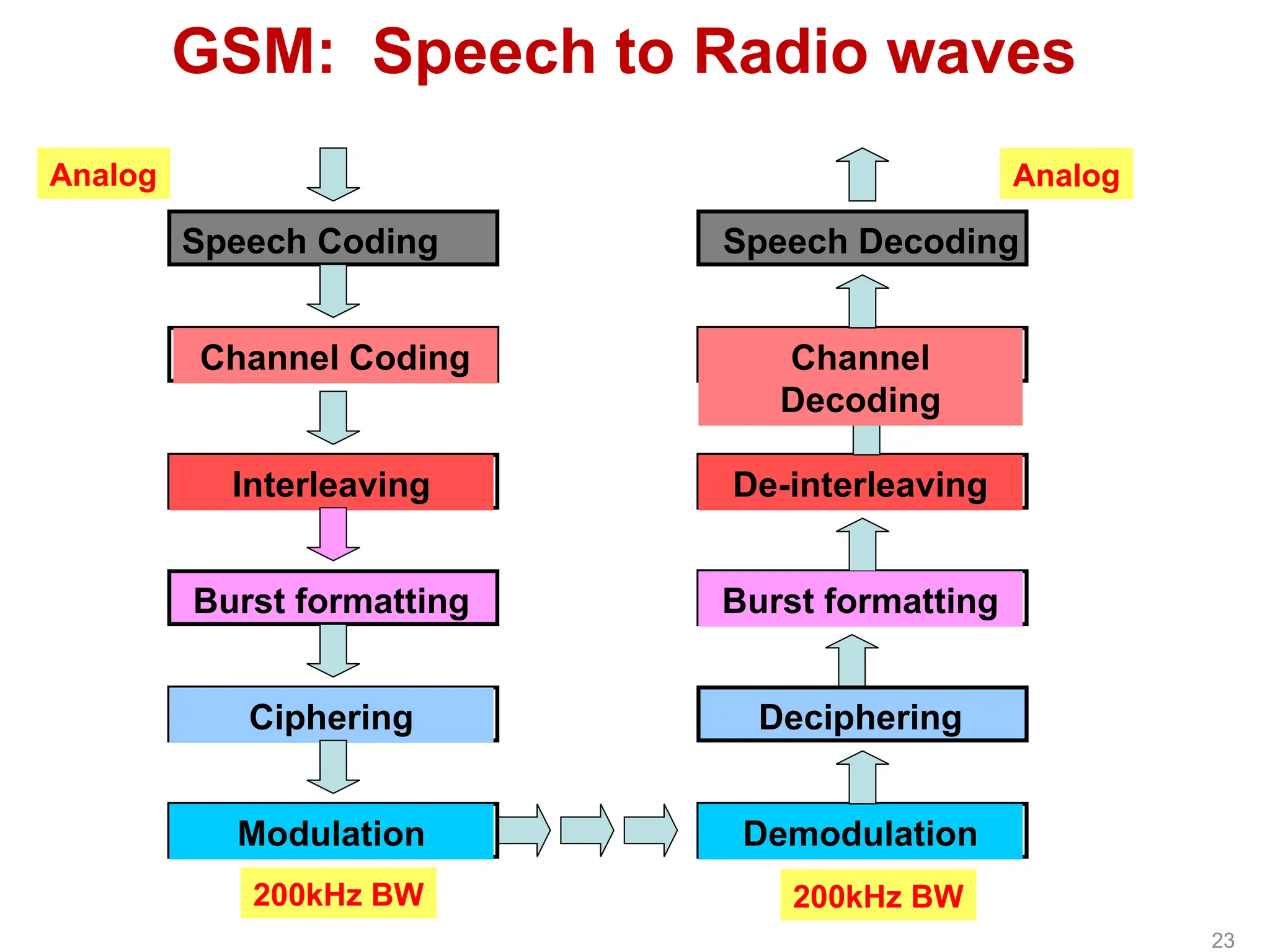
Digital Voice Transmission
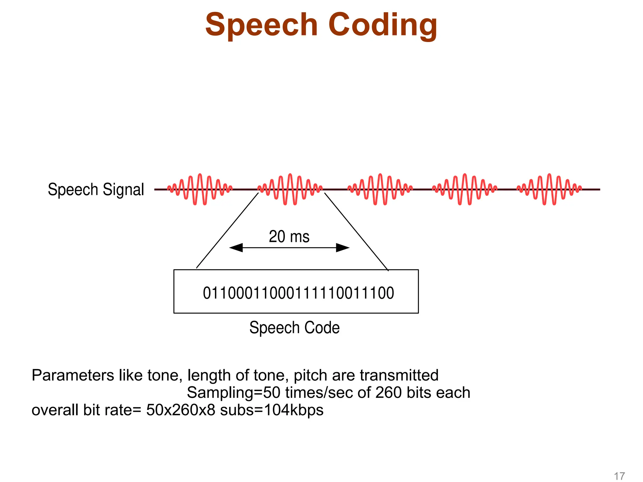
-In GSM speech coding a block of 20 ms is encoded in one set
of 260 bits.
- This calculates as 50X 260 = 13 kbps. Thus GSM speech
coder produces a bit rate of 13 kbps per subscriber.
- This provides speech quality which is acceptable for mobile
telephony and comparable with wire-line PSTN phones.
Speech Coding
16
17.
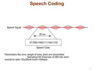
01100011000111110011100
Speech Code
20 ms
SpeechSignal
Speech Coding
Parameters like tone, length of tone, pitch are transmitted
Sampling=50 times/sec of 260 bits each
overall bit rate= 50x260x8 subs=104kbps
17
18.
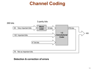
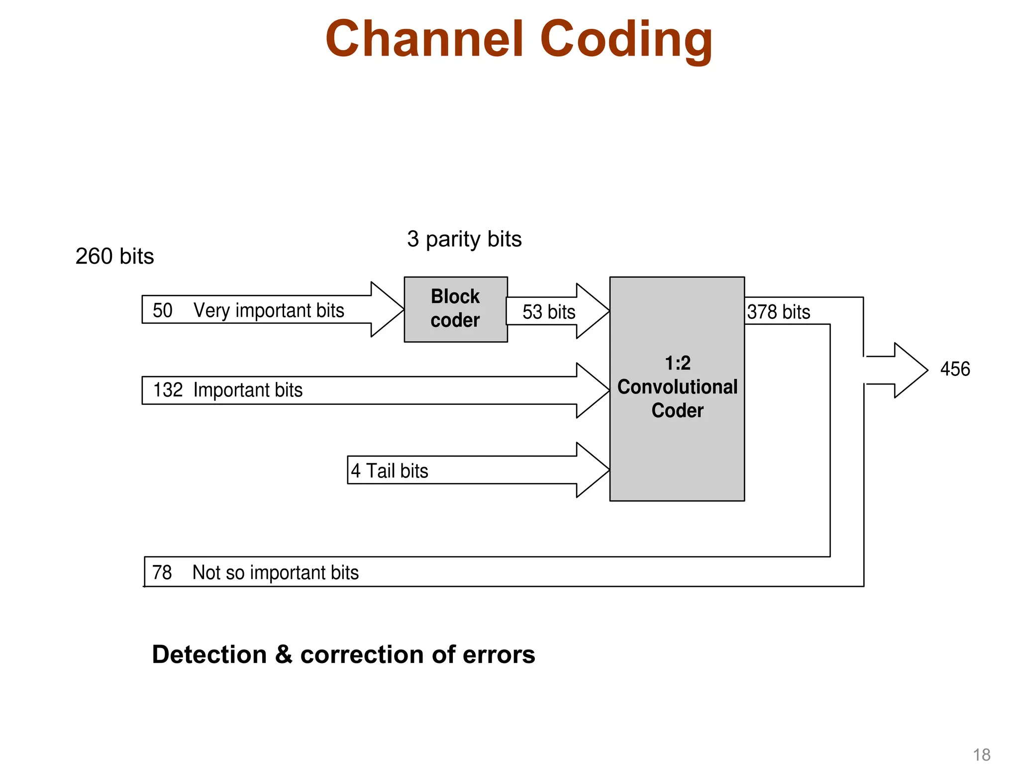
Channel Coding
Block
coder
50 Veryimportant bits
132 Important bits
78 Not so important bits
1:2
Convolutional
Coder
456
4 Tail bits
53 bits 378 bits
3 parity bits
260 bits
Detection & correction of errors
18
19.
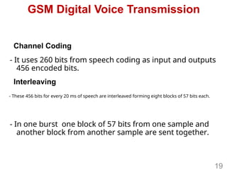
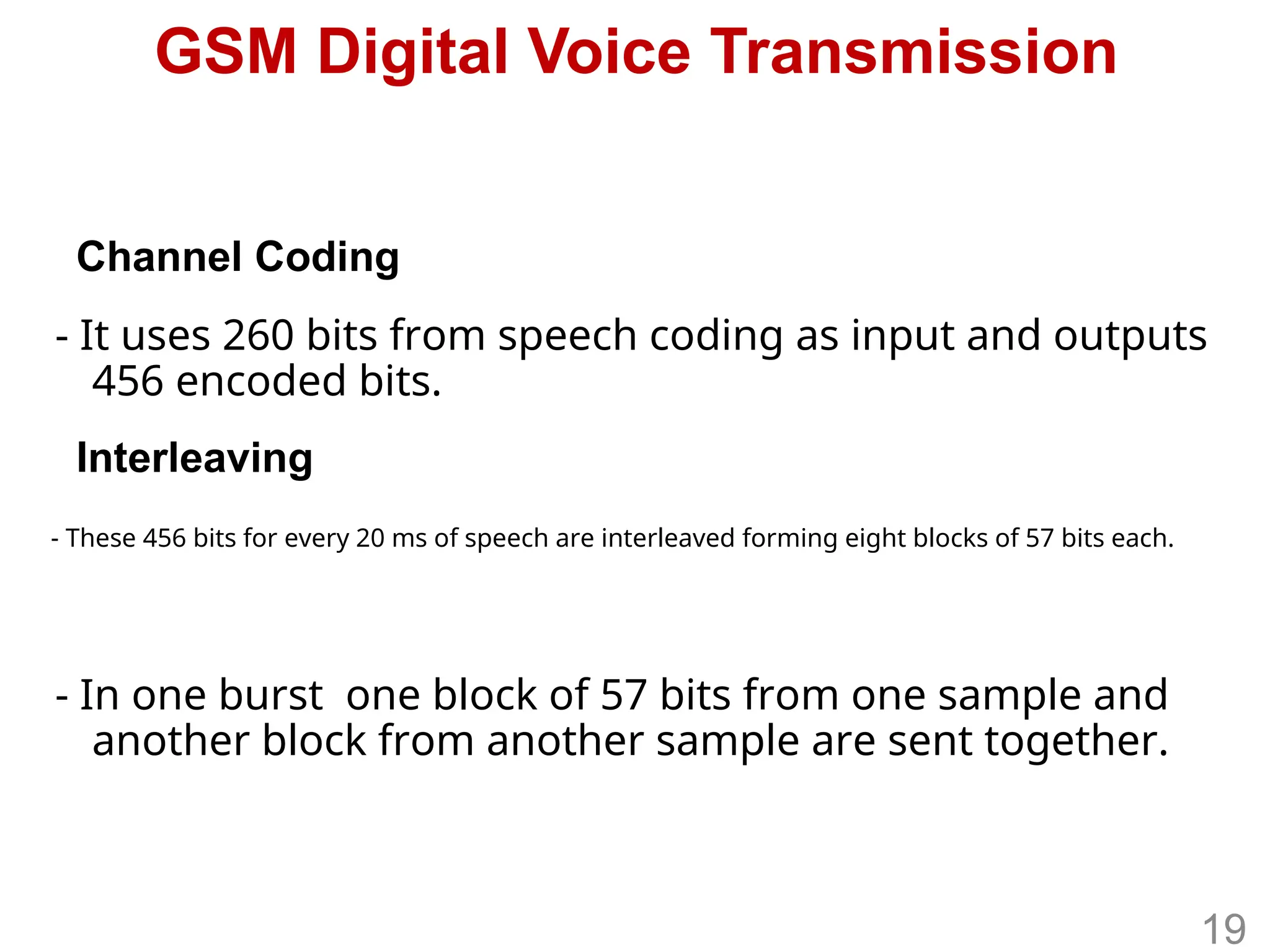
GSM Digital VoiceTransmission
- It uses 260 bits from speech coding as input and outputs
456 encoded bits.
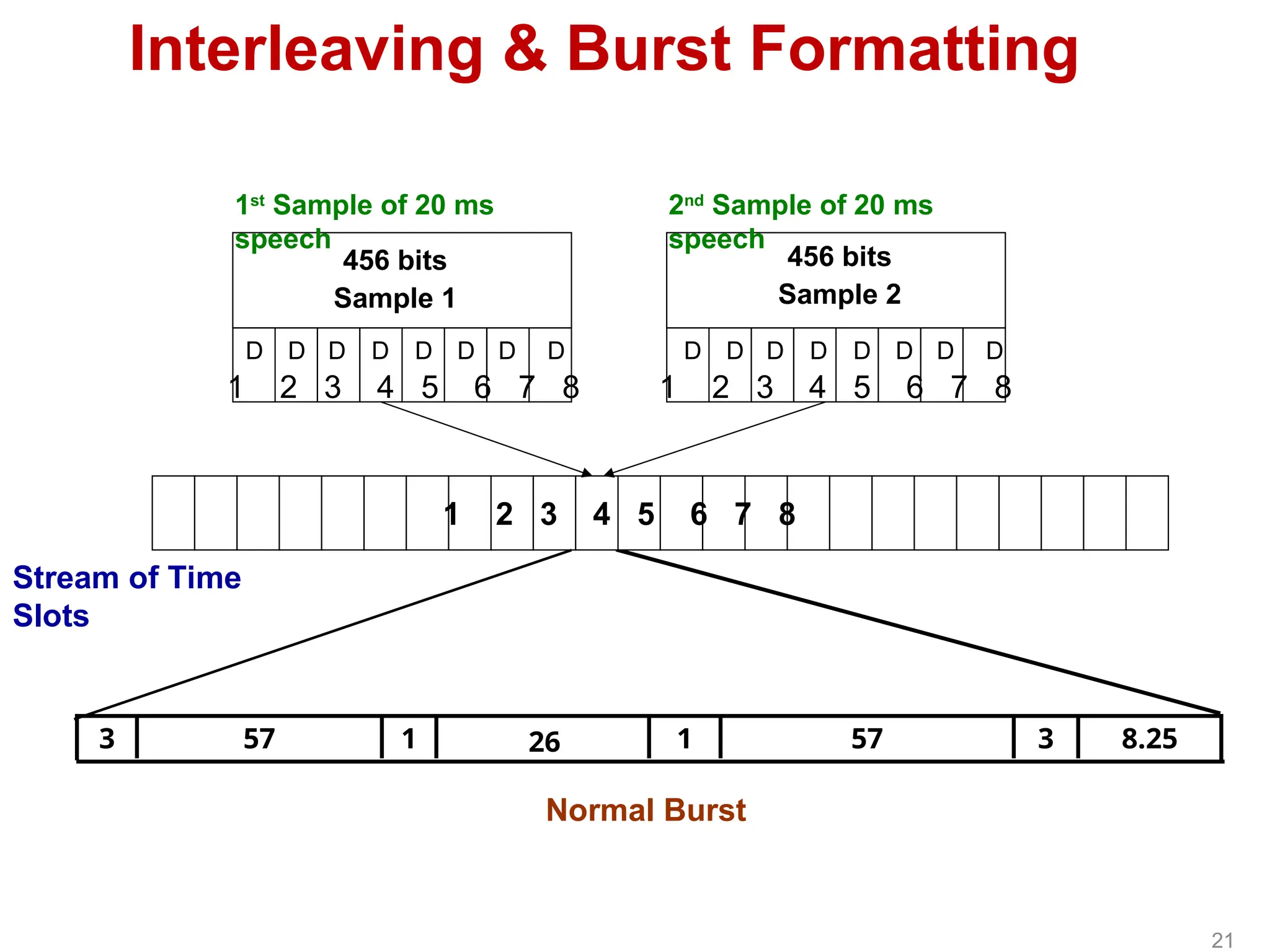
- In one burst one block of 57 bits from one sample and
another block from another sample are sent together.
- These 456 bits for every 20 ms of speech are interleaved forming eight blocks of 57 bits each.
Channel Coding
Interleaving
19
20.
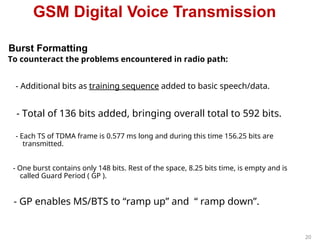
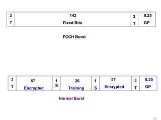
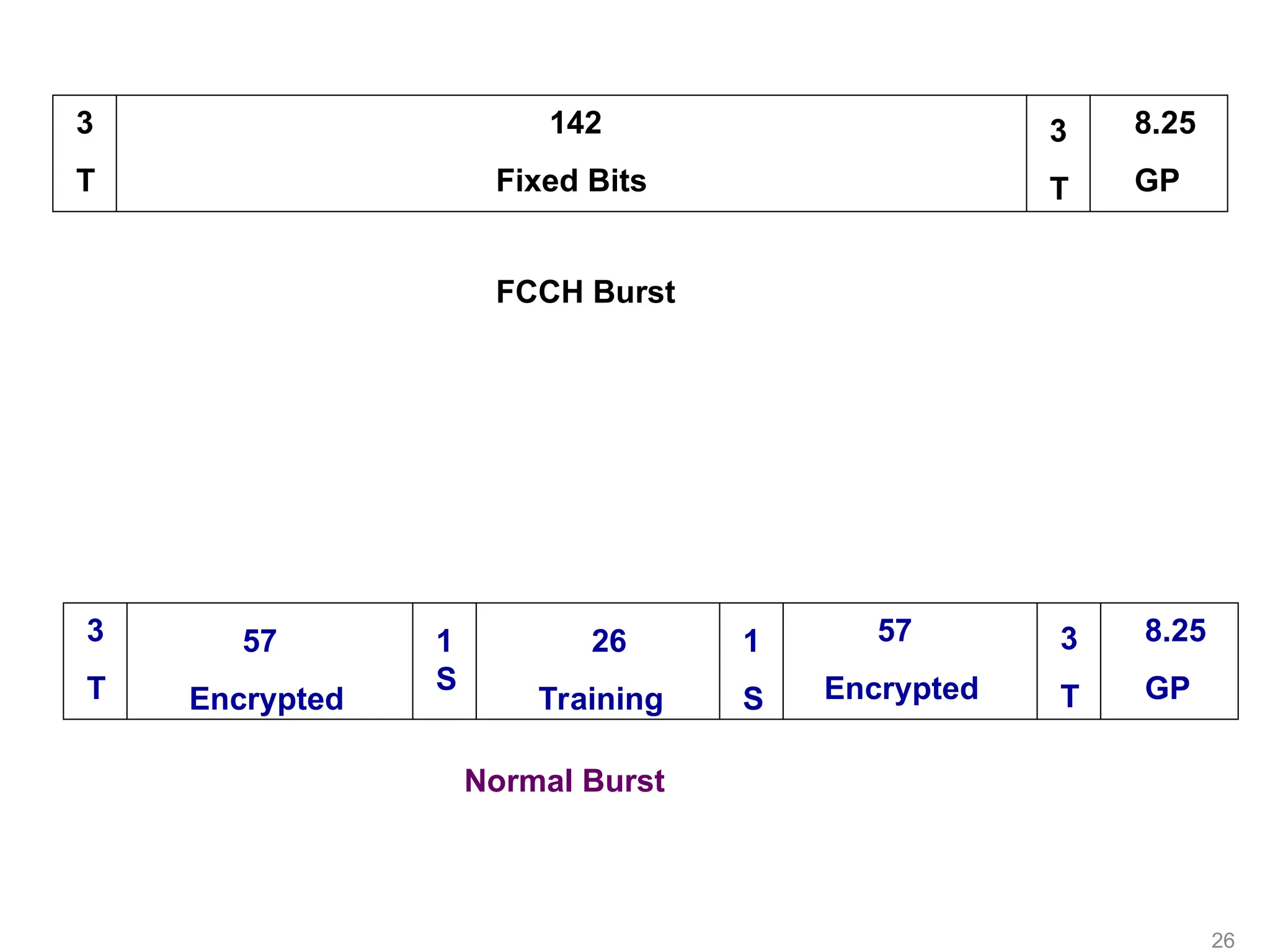
GSM Digital VoiceTransmission
To counteract the problems encountered in radio path:
Burst Formatting
- Additional bits as training sequence added to basic speech/data.
- Total of 136 bits added, bringing overall total to 592 bits.
- Each TS of TDMA frame is 0.577 ms long and during this time 156.25 bits are
transmitted.
- One burst contains only 148 bits. Rest of the space, 8.25 bits time, is empty and is
called Guard Period ( GP ).
- GP enables MS/BTS to “ramp up” and “ ramp down”.
20
21.
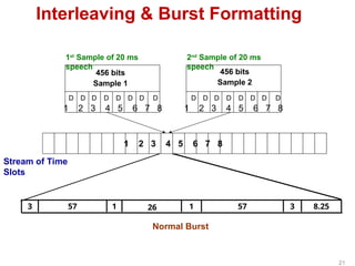
8.25
3
57
1
26
1
57
3
1 2 34 5 6 7 8
1 2 3 4 5 6 7 8 1 2 3 4 5 6 7 8
D D D D D
D
D D D D D D D
D
D D
456 bits
Sample 1
456 bits
Sample 2
Normal Burst
Stream of Time
Slots
Interleaving & Burst Formatting
1st
Sample of 20 ms
speech
2nd
Sample of 20 ms
speech
21
vYV lsaVj
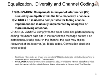
Equalization, Diversityand Channel Coding
EQUALIZATION: Compensate intersymbol interference (ISI)
created by multipath within the time dispersive channels.
DIVERSITY : It is used to compensate for fading channel
impairment and is usually implemented by using two or
more receiving antennas,
CHANNEL CODING: it improves the small scale link performance by
adding redundant data bits in the transmitted message so that if an
instantaneous fade occur in the channel the data may still be
recovered at the receiver.(ex: Block codes, Convolution code and
turbo codes)
– Block Codes : Block codes are forward error correction (FEC) codes that enable a limited numbers of error to
be detected without retransmission.( Channel Coding)
– INTERLEAVER: Function of interleaver to spread these bit out in time so that if there is a deep fade or noise
bursts the important bits from a block of source data do not corrupted at the same time.( Time Diversity)
24
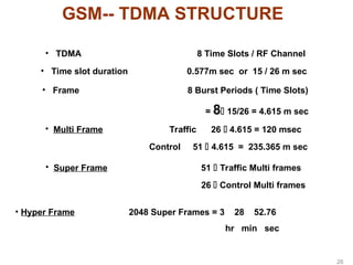
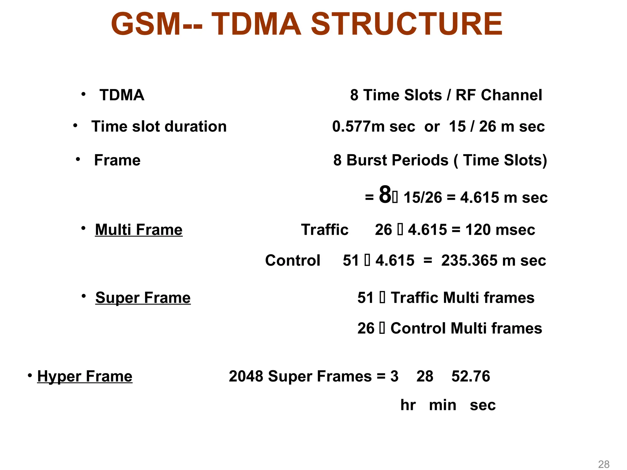
GSM-- TDMA STRUCTURE
•TDMA 8 Time Slots / RF Channel
• Time slot duration 0.577m sec or 15 / 26 m sec
• Frame 8 Burst Periods ( Time Slots)
= 8 15/26 = 4.615 m sec
• Multi Frame Traffic 26 4.615 = 120 msec
Control 51 4.615 = 235.365 m sec
• Super Frame 51 Traffic Multi frames
26 Control Multi frames
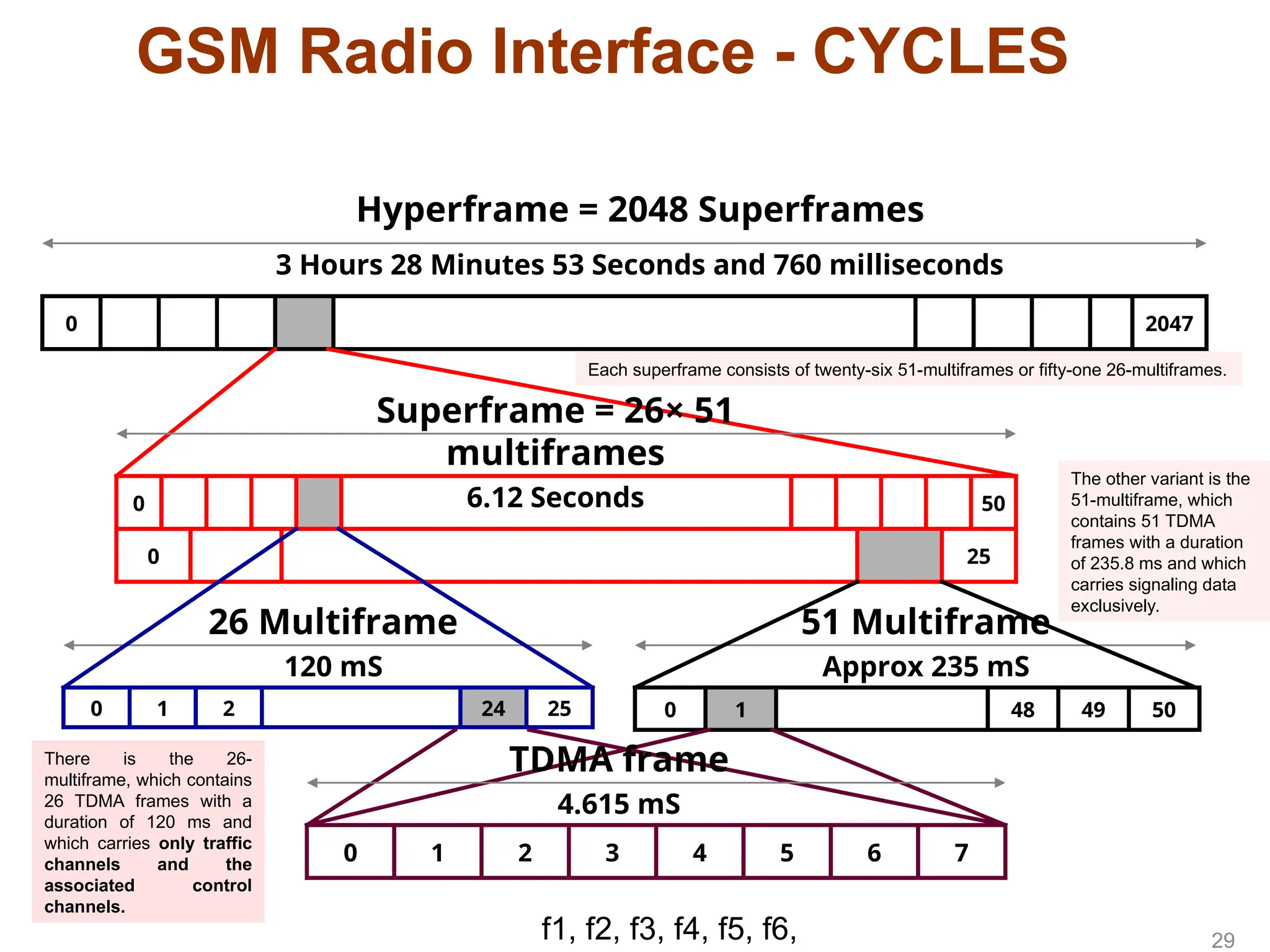
• Hyper Frame 2048 Super Frames = 3 28 52.76
hr min sec
28
28.
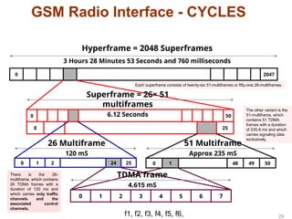
GSM Radio Interface- CYCLES
2047
0
Hyperframe = 2048 Superframes
3 Hours 28 Minutes 53 Seconds and 760 milliseconds
50
0
25
0
Superframe = 26× 51
multiframes
6.12 Seconds
51 Multiframe
Approx 235 mS
26 Multiframe
120 mS
25
24
2
1
0 50
49
48
1
0
7
6
5
4
3
2
1
0
TDMA frame
4.615 mS
29
f1, f2, f3, f4, f5, f6,
There is the 26-
multiframe, which contains
26 TDMA frames with a
duration of 120 ms and
which carries only traffic
channels and the
associated control
channels.
The other variant is the
51-multiframe, which
contains 51 TDMA
frames with a duration
of 235.8 ms and which
carries signaling data
exclusively.
Each superframe consists of twenty-six 51-multiframes or fifty-one 26-multiframes.
29.
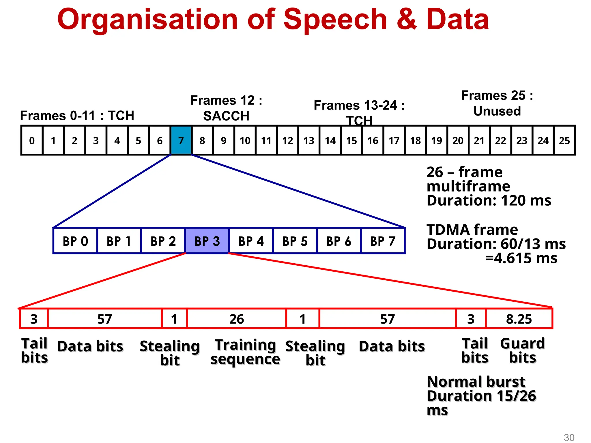
Organisation of Speech& Data
24 25
23
22
21
20
19
18
17
16
15
14
13
12
11
10
9
8
7
6
5
4
3
2
1
0
BP 7
BP 6
BP 5
BP 4
BP 3
BP 2
BP 1
BP 0
8.25
3
57
1
26
1
57
3
Frames 0-11 : TCH
Frames 12 :
SACCH
Frames 13-24 :
TCH
Frames 25 :
Unused
26 – frame
multiframe
Duration: 120 ms
TDMA frame
Duration: 60/13 ms
=4.615 ms
Tail
Tail
bits
bits
Data bits
Data bits Stealing
Stealing
bit
bit
Training
Training
sequence
sequence
Stealing
Stealing
bit
bit
Data bits
Data bits Tail
Tail
bits
bits
Guard
Guard
bits
bits
Normal burst
Normal burst
Duration 15/26
Duration 15/26
ms
ms
30
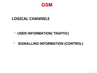
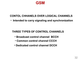
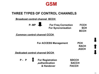
GSM
CONTOL CHHANELS OVERLOGICAL CHANNELS
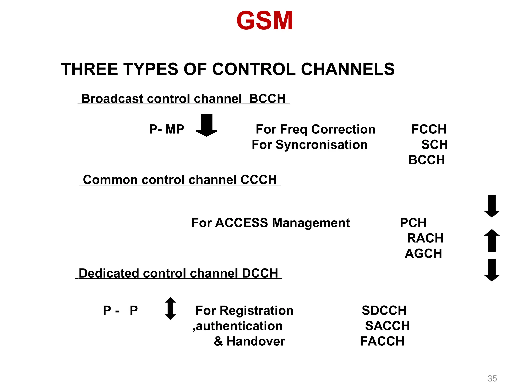
THREE TYPES OF CONTROL CHANNELS
• Intended to carry signaling and synchronization
• Broadcast control channel BCCH
• Common control channel CCCH
• Dedicated control channel DCCH
32
34
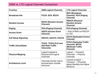
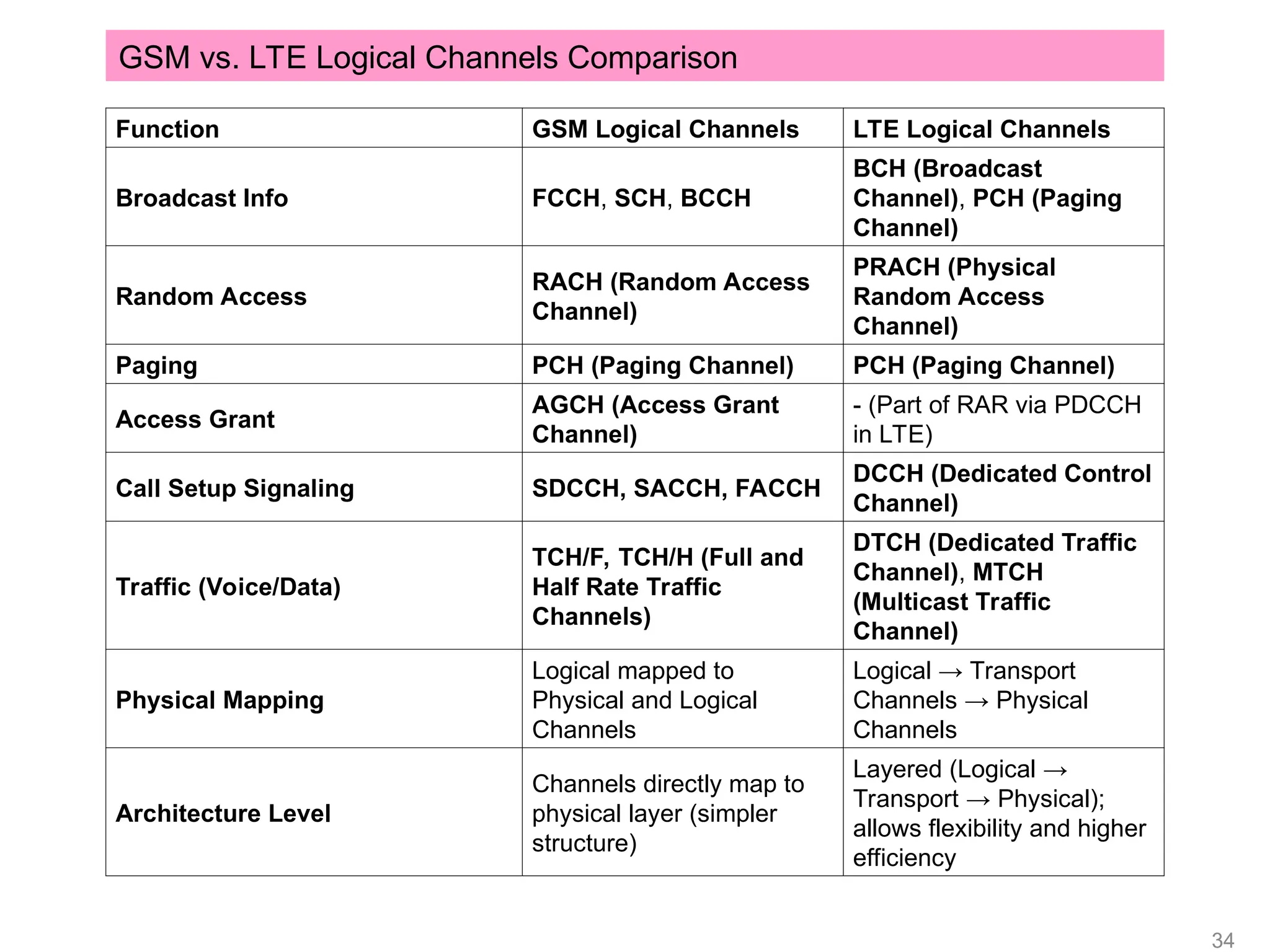
Function GSM LogicalChannels LTE Logical Channels
Broadcast Info FCCH, SCH, BCCH
BCH (Broadcast
Channel), PCH (Paging
Channel)
Random Access
RACH (Random Access
Channel)
PRACH (Physical
Random Access
Channel)
Paging PCH (Paging Channel) PCH (Paging Channel)
Access Grant
AGCH (Access Grant
Channel)
- (Part of RAR via PDCCH
in LTE)
Call Setup Signaling SDCCH, SACCH, FACCH
DCCH (Dedicated Control
Channel)
Traffic (Voice/Data)
TCH/F, TCH/H (Full and
Half Rate Traffic
Channels)
DTCH (Dedicated Traffic
Channel), MTCH
(Multicast Traffic
Channel)
Physical Mapping
Logical mapped to
Physical and Logical
Channels
Logical → Transport
Channels → Physical
Channels
Architecture Level
Channels directly map to
physical layer (simpler
structure)
Layered (Logical →
Transport → Physical);
allows flexibility and higher
efficiency
GSM vs. LTE Logical Channels Comparison
34.
GSM
THREE TYPES OFCONTROL CHANNELS
Dedicated control channel DCCH
P - P For Registration SDCCH
,authentication SACCH
& Handover FACCH
Broadcast control channel BCCH
P- MP For Freq Correction FCCH
For Syncronisation SCH
BCCH
Common control channel CCCH
For ACCESS Management PCH
RACH
AGCH
35
35.
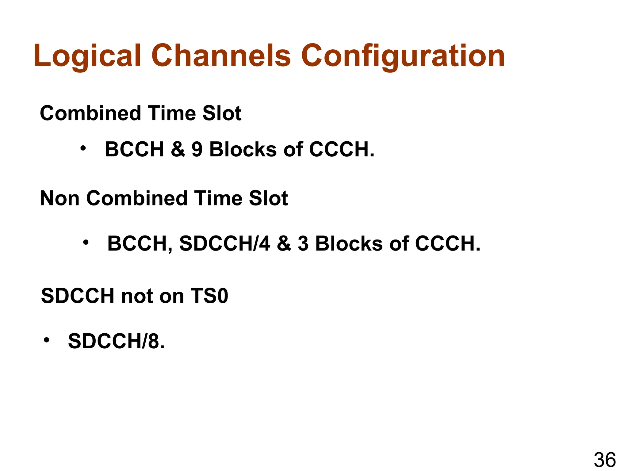
Logical Channels Configuration
CombinedTime Slot
• BCCH & 9 Blocks of CCCH.
Non Combined Time Slot
• BCCH, SDCCH/4 & 3 Blocks of CCCH.
SDCCH not on TS0
• SDCCH/8.
36
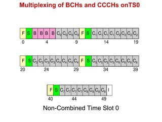
36.
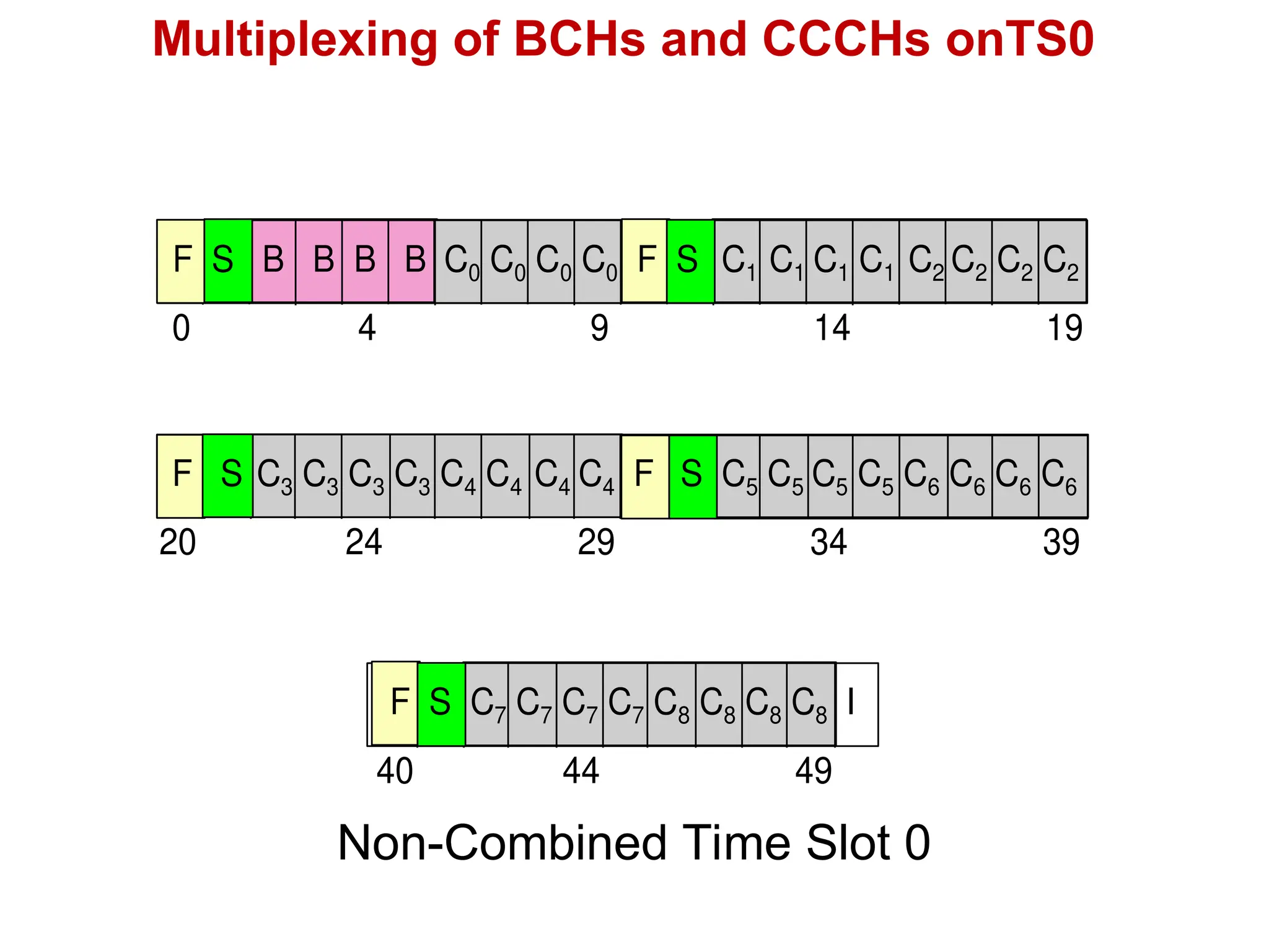
Multiplexing of BCHsand CCCHs onTS0
0 4 9 14 19
F S B B B B C0 C0 C0 C0 F S C1 C1 C1 C1 C2 C2 C2 C2
20 24 29 34 39
F S C3 C3 C3 C3 C4 C4 C4 C4 F S C5 C5 C5 C5 C6 C6 C6 C6
40 44 49
F S C7 C7 C7 C7 C8 C8 C8 C8 I
Non-Combined Time Slot 0
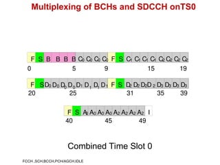
37.
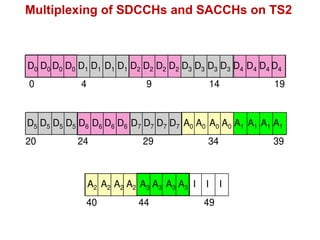
Multiplexing of BCHsand SDCCH onTS0
0 5 9 15 19
F S B B B B C0 C0 C0 C0 F S C1 C1 C1 C1 C2 C2 C2 C2
20 25 31 35 39
F SD0 1 1 1 F S D2 D2 D2D 2 D3 D3 D3 D3
0 0 0 1
40 45 49
F S A
0 A0 A0 A0 A2 A2 A2 A2 I
D D
D D D D D
Combined Time Slot 0
FCCH ,SCH,BCCH,PCH/AGCH,IDLE
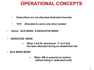
OPERATIONAL CONCEPTS
• Subscribersare not allocated dedicated channels
• TCH Allocated to users only when needed
• Hence IDLE MODE & DEDICATED MODE
• DEDICATED MODE
-- When a full Bi -directional P to P CHL
has been allocated during an established call
• IDLE MODE MODE
-- When MS is powered on (active)
without being in dedicated mode
40
40.
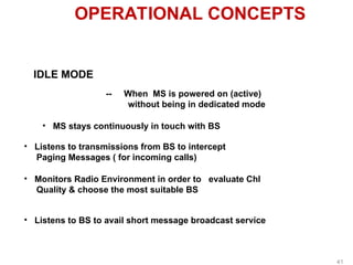
OPERATIONAL CONCEPTS
IDLE MODE
--When MS is powered on (active)
without being in dedicated mode
• MS stays continuously in touch with BS
• Listens to transmissions from BS to intercept
Paging Messages ( for incoming calls)
• Monitors Radio Environment in order to evaluate Chl
Quality & choose the most suitable BS
• Listens to BS to avail short message broadcast service
41
41.
OPERATIONAL CONCEPTS
ACCESS PROCEDURE
--Access to system
( switch over from IDLE to DEDICATED Mode)
• MS indicates to BS that it needs a connection
• BS accepts the request & indicates which
traffic CHL it may use
• For above purpose specific transmission is done over
“ Common Channels”
42
42.
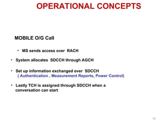
OPERATIONAL CONCEPTS
MOBILE O/GCall
• MS sends access over RACH
• System allocates SDCCH through AGCH
• Lastly TCH is assigned through SDCCH when a
conversation can start
• Set up information exchanged over SDCCH
( Authentication , Measurement Reports, Power Control)
43
43.
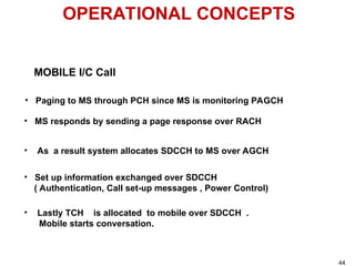
OPERATIONAL CONCEPTS
MOBILE I/CCall
• Paging to MS through PCH since MS is monitoring PAGCH
• MS responds by sending a page response over RACH
• Set up information exchanged over SDCCH
( Authentication, Call set-up messages , Power Control)
• As a result system allocates SDCCH to MS over AGCH
• Lastly TCH is allocated to mobile over SDCCH .
Mobile starts conversation.
44
44.
Other Salient FeaturesOf GSM RF INTERFACE:
GSM – RF Interface
- Control of Transmitted Power.
- Timing Advance.
- Discontinuous Transmission.
- Diversity.
- Frequency Hopping.
45
45.
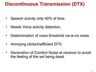
Discontinuous Transmission (DTX)
•Speech activity only 40% of time.
• Needs Voice activity detection.
• Determination of voice threshold vis-à-vis noise.
• Annoying clicks/inefficient DTX.
• Generation of Comfort Noise at receiver to avoid
the feeling of the set being dead.
46
46.
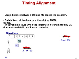
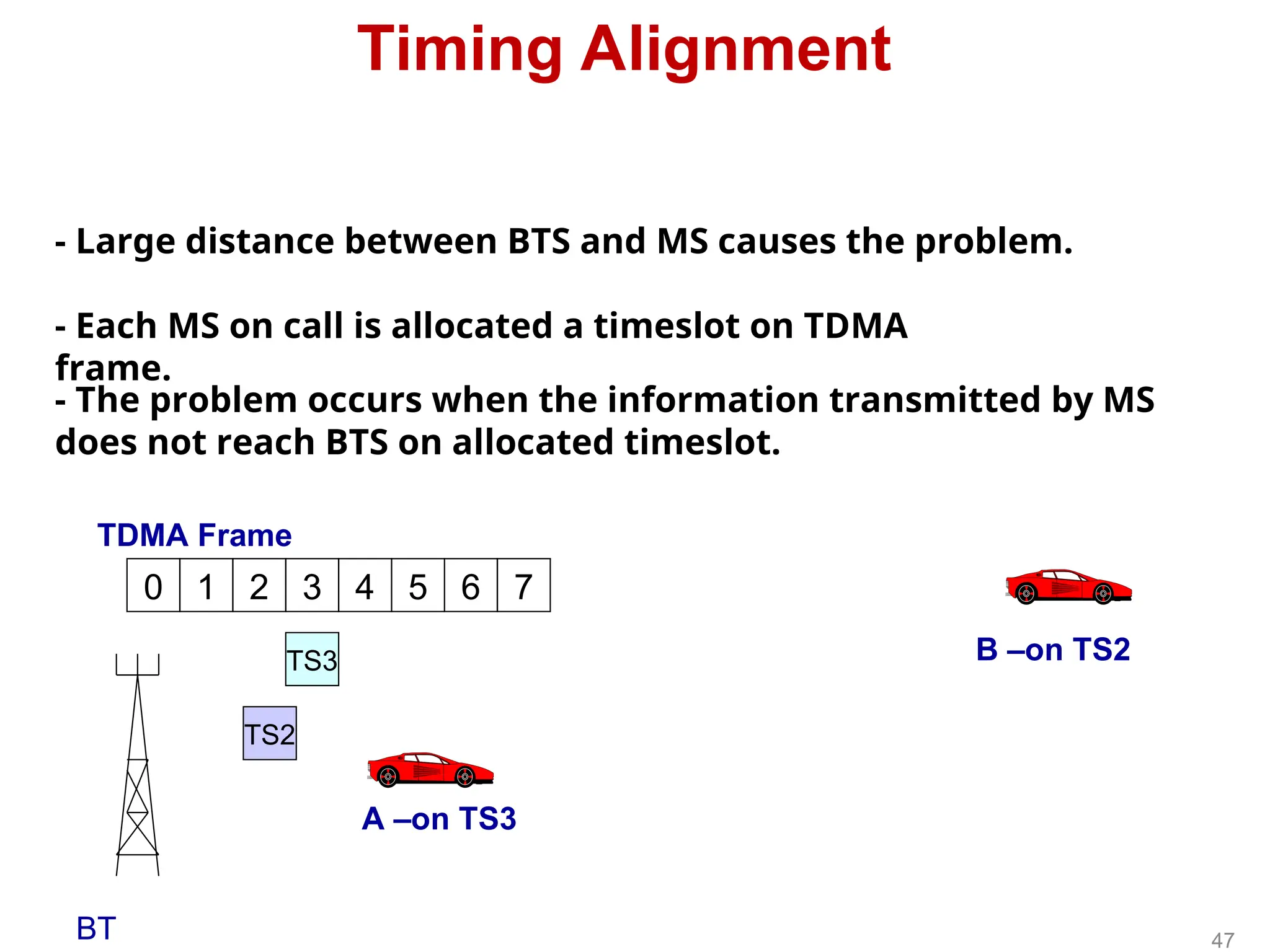
Timing Alignment
- Largedistance between BTS and MS causes the problem.
- Each MS on call is allocated a timeslot on TDMA
frame.
- The problem occurs when the information transmitted by MS
does not reach BTS on allocated timeslot.
0 1 2 3 4 5 6 7
BT
TDMA Frame
A –on TS3
B –on TS2
TS3
TS2
47
47.
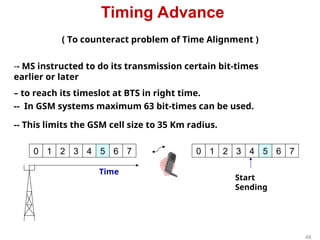
Timing Advance
( Tocounteract problem of Time Alignment )
-- MS instructed to do its transmission certain bit-times
earlier or later
– to reach its timeslot at BTS in right time.
-- In GSM systems maximum 63 bit-times can be used.
-- This limits the GSM cell size to 35 Km radius.
0 1 2 3 4 5 6 7 0 1 2 3 4 5 6 7
Time
Start
Sending
48
48.
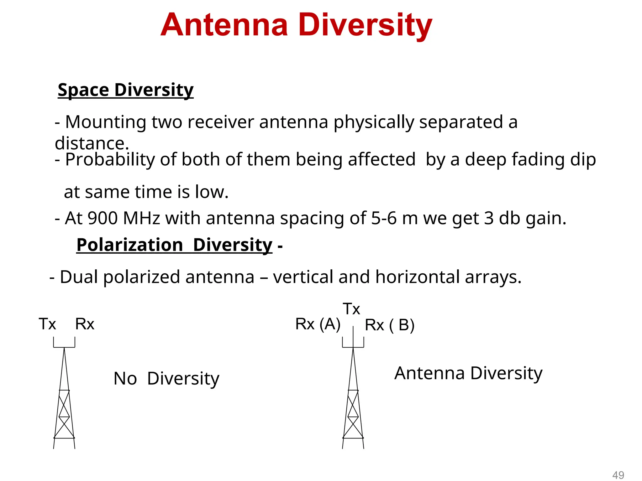
Antenna Diversity
- Mountingtwo receiver antenna physically separated a
distance.
- At 900 MHz with antenna spacing of 5-6 m we get 3 db gain.
Space Diversity
- Probability of both of them being affected by a deep fading dip
at same time is low.
No Diversity Antenna Diversity
Tx Rx Rx (A) Rx ( B)
Tx
Polarization Diversity -
- Dual polarized antenna – vertical and horizontal arrays.
49
49.
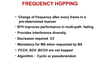
FREQUENCY HOPPING
• Changeof frequency after every frame in a
pre-determined manner
• SFH improves performance in multi-path fading
• Decreases required C/I
• Mandatory for MS when requested by BS
• FCCH ,SCH ,BCCH are not hopped
• Algorithm : Cyclic or pseudorandom
• Provides interference diversity
50.
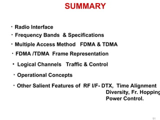
SUMMARY
• Radio Interface
•Frequency Bands & Specifications
• Multiple Access Method FDMA & TDMA
• FDMA /TDMA Frame Representation
• Logical Channels Traffic & Control
• Operational Concepts
• Other Salient Features of RF I/F- DTX, Time Alignment
Diversity, Fr. Hopping
Power Control.
51
#29 In a GSM system, every TDMA frame is assigned a fixed number, which repeats itself in a time period of 3 hours, 28 minutes, 53 seconds, and 760 milliseconds.