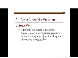
2.1 Basic Assembler
Functions
3
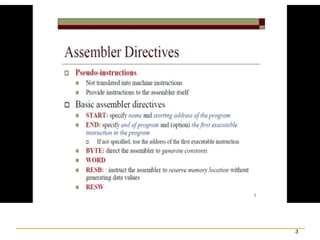
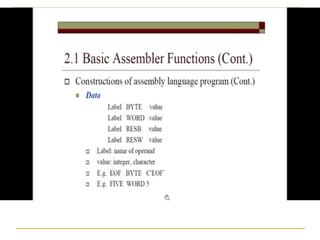
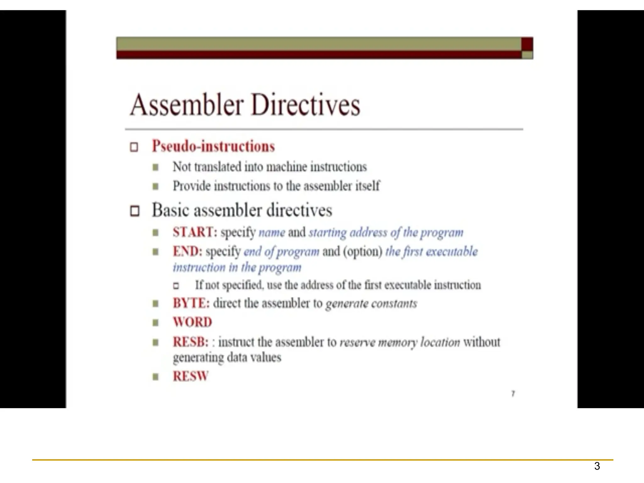
Assembler directives (pseudo-instructions)
START
, END, BYTE, WORD, RESB, RESW.
These statements are not translated into
machine instructions.
Instead, they provide instructions to the
assembler itself.
7.
7
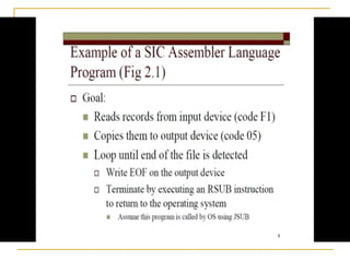
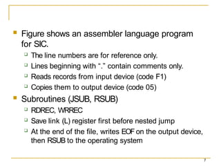
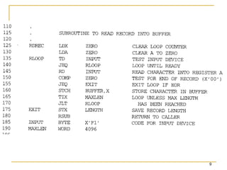
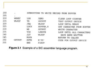
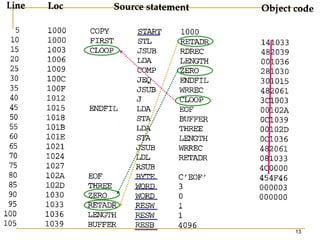
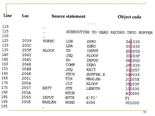
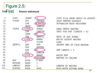
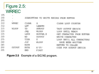
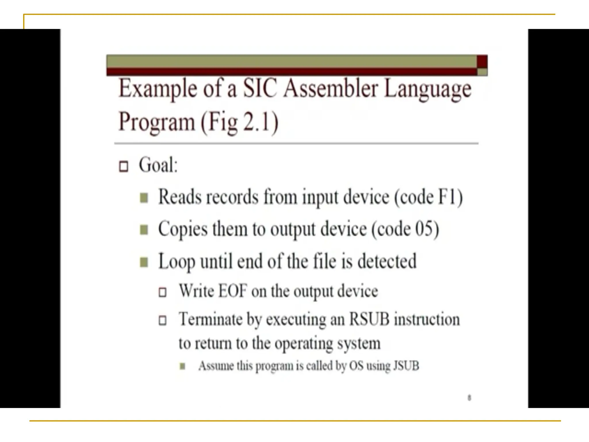
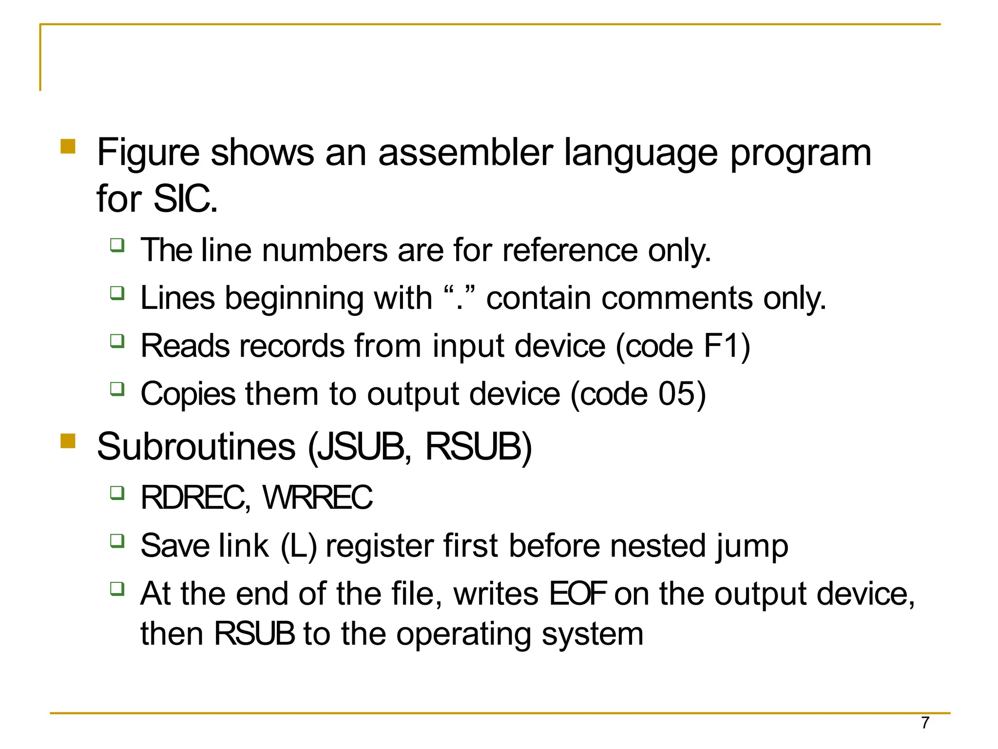
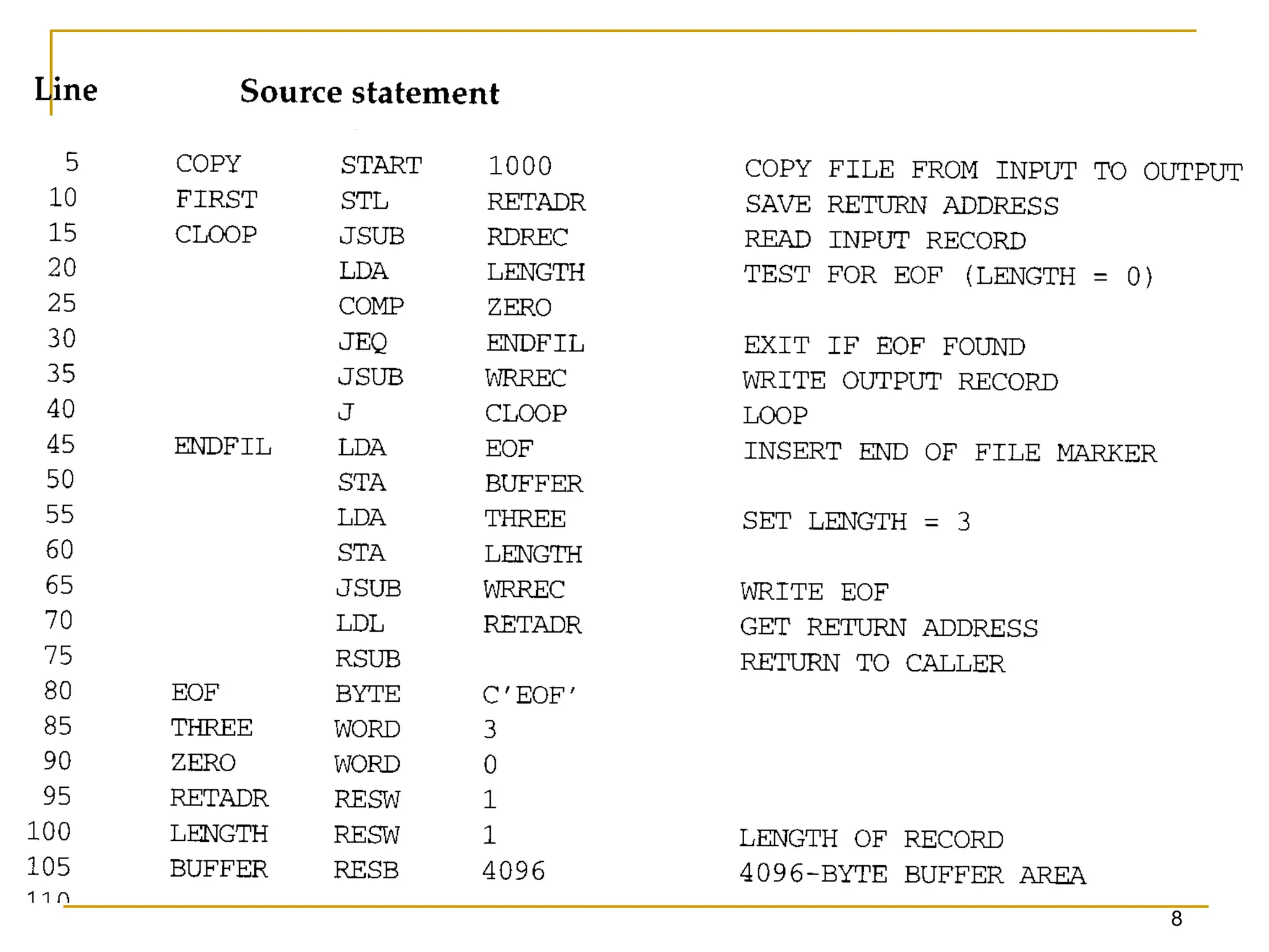
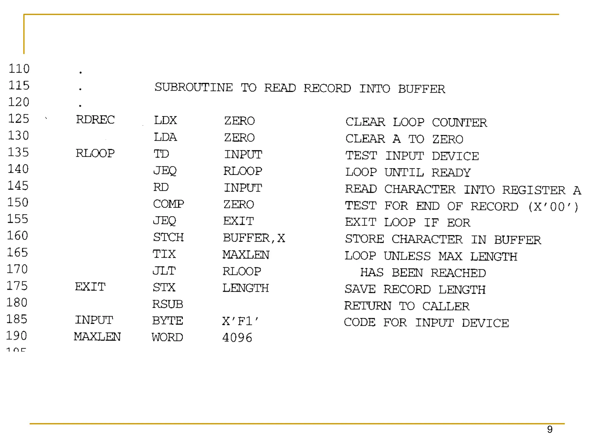
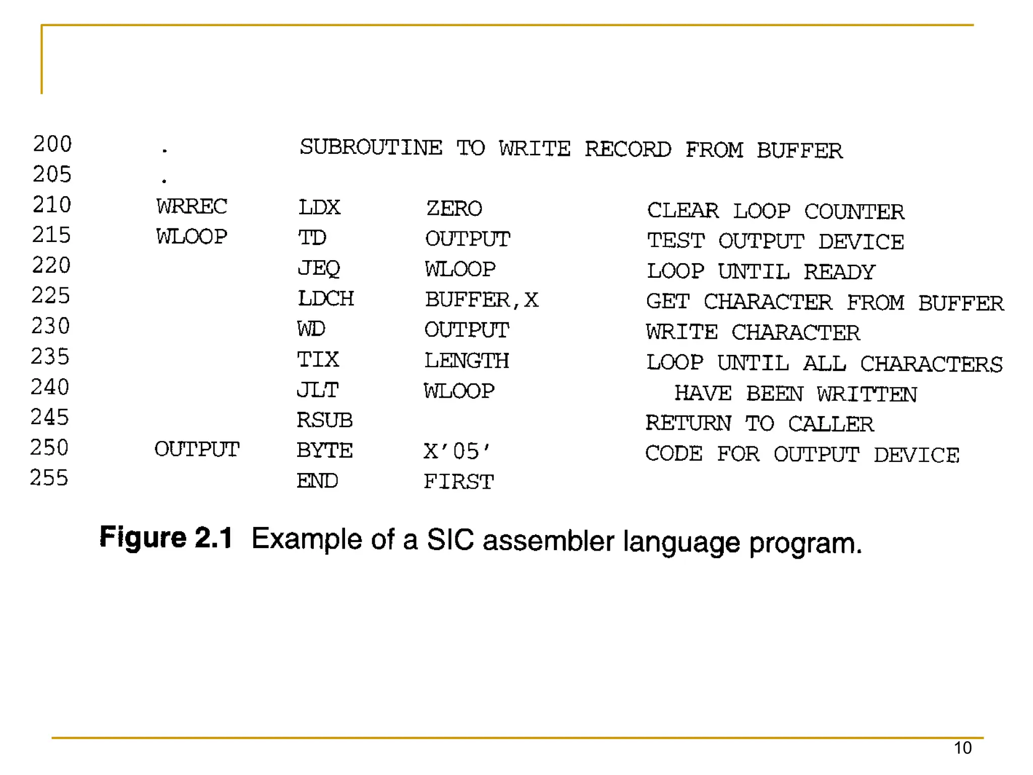
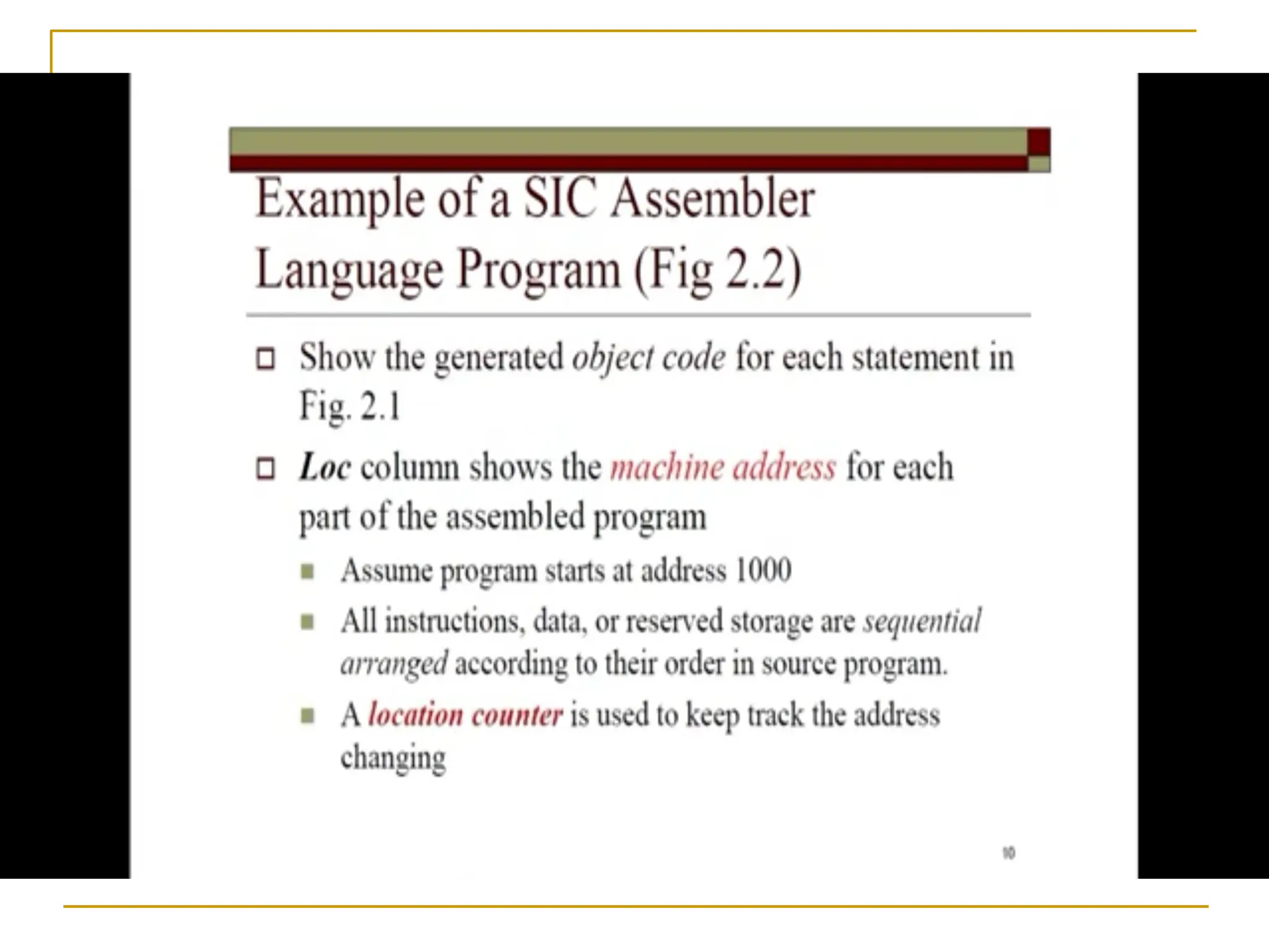
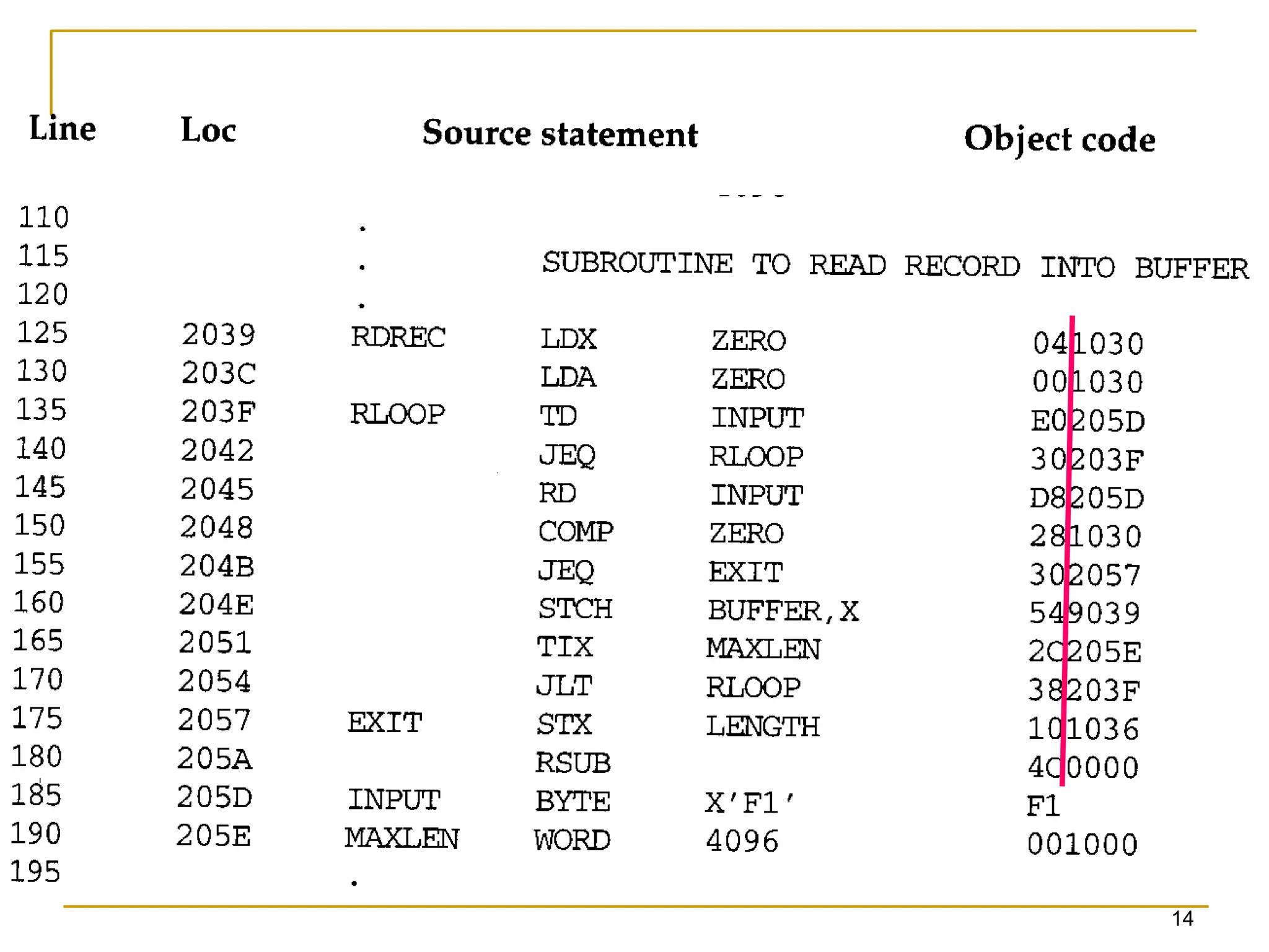
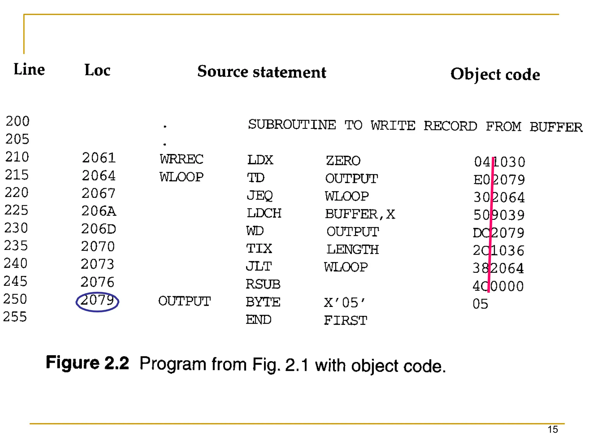
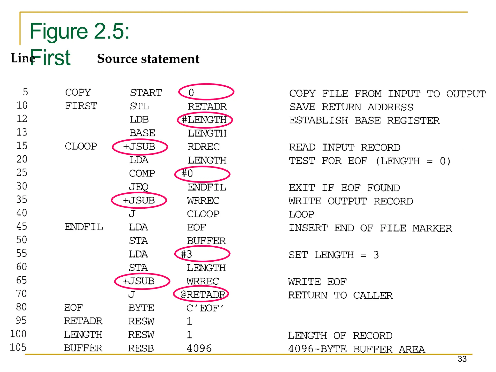
Figure showsan assembler language program
for SIC.
The line numbers are for reference only.
Lines beginning with “.” contain comments only.
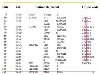
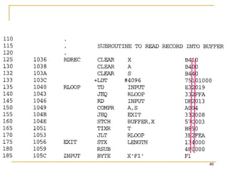
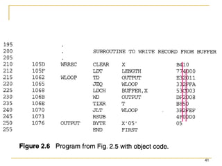
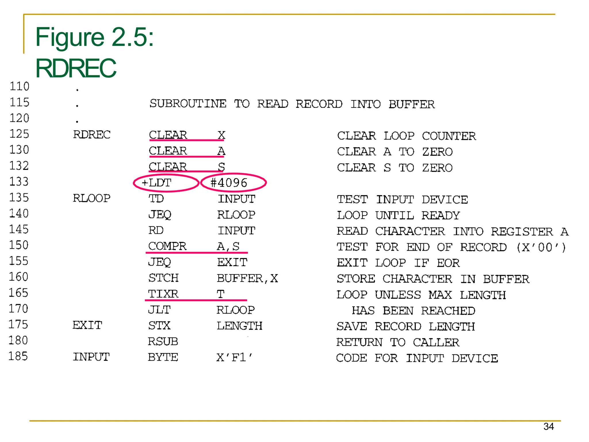
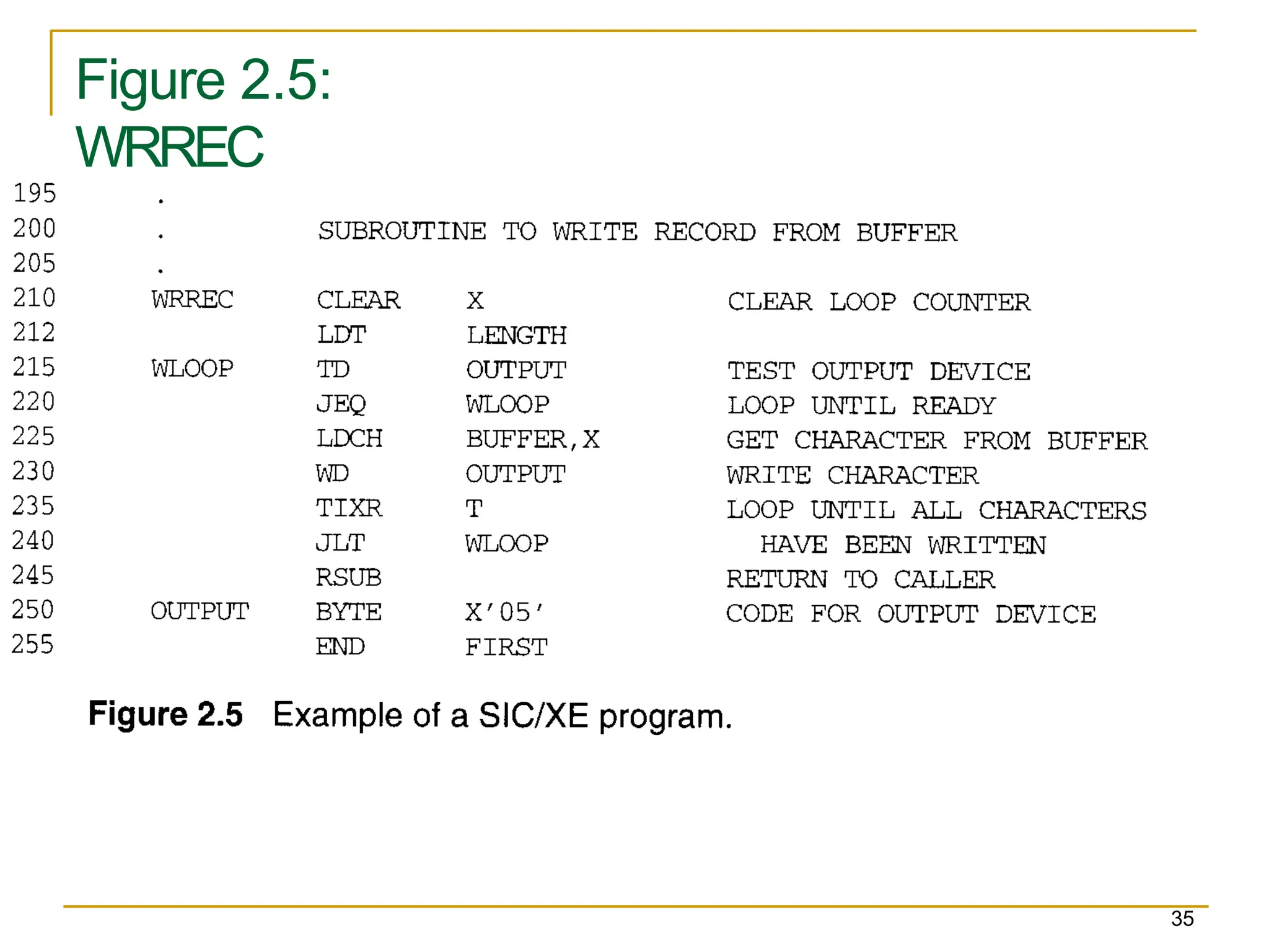
Reads records from input device (code F1)
Copies them to output device (code 05)
Subroutines (JSUB, RSUB)
RDREC, WRREC
Save link (L) register first before nested jump
At the end of the file, writes EOF on the output device,
then RSUB to the operating system
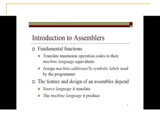
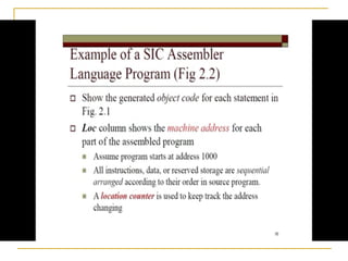
2.1.1 A simpleSIC
Assembler
16
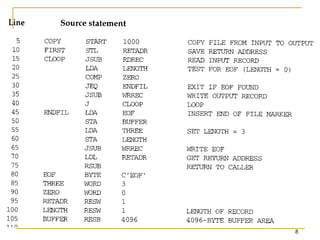
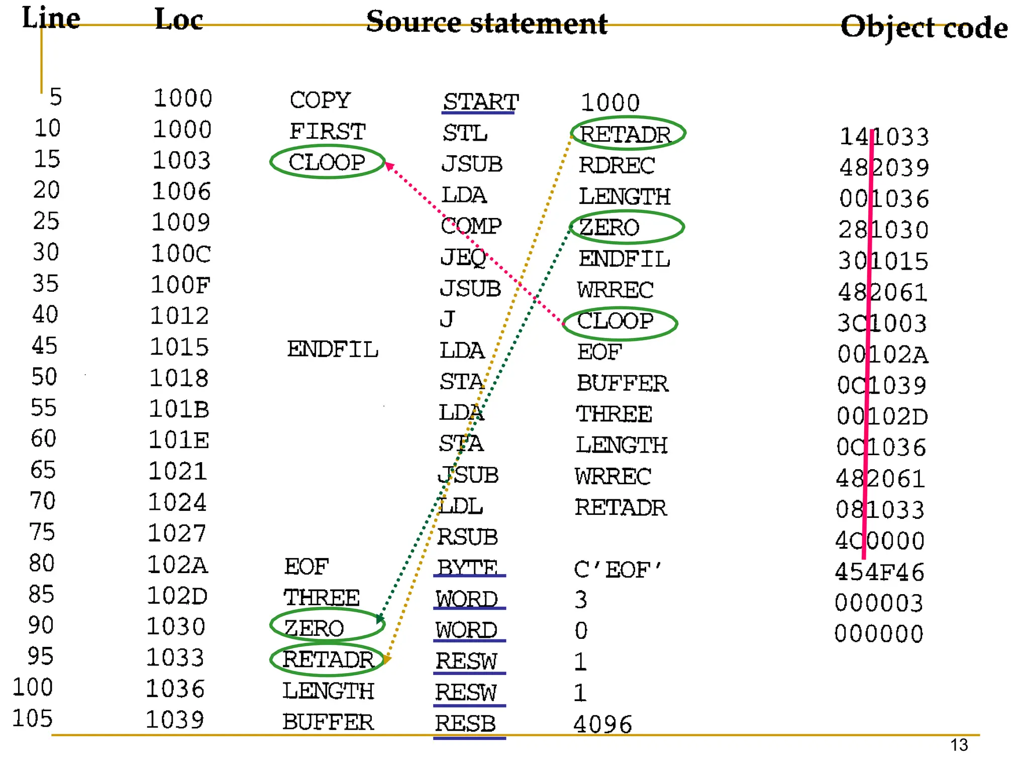
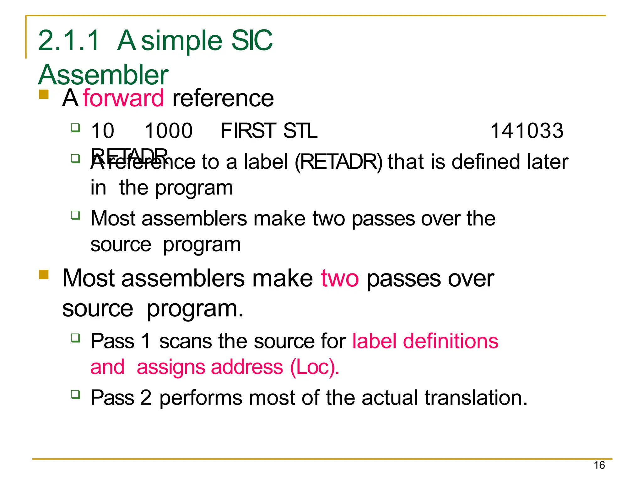
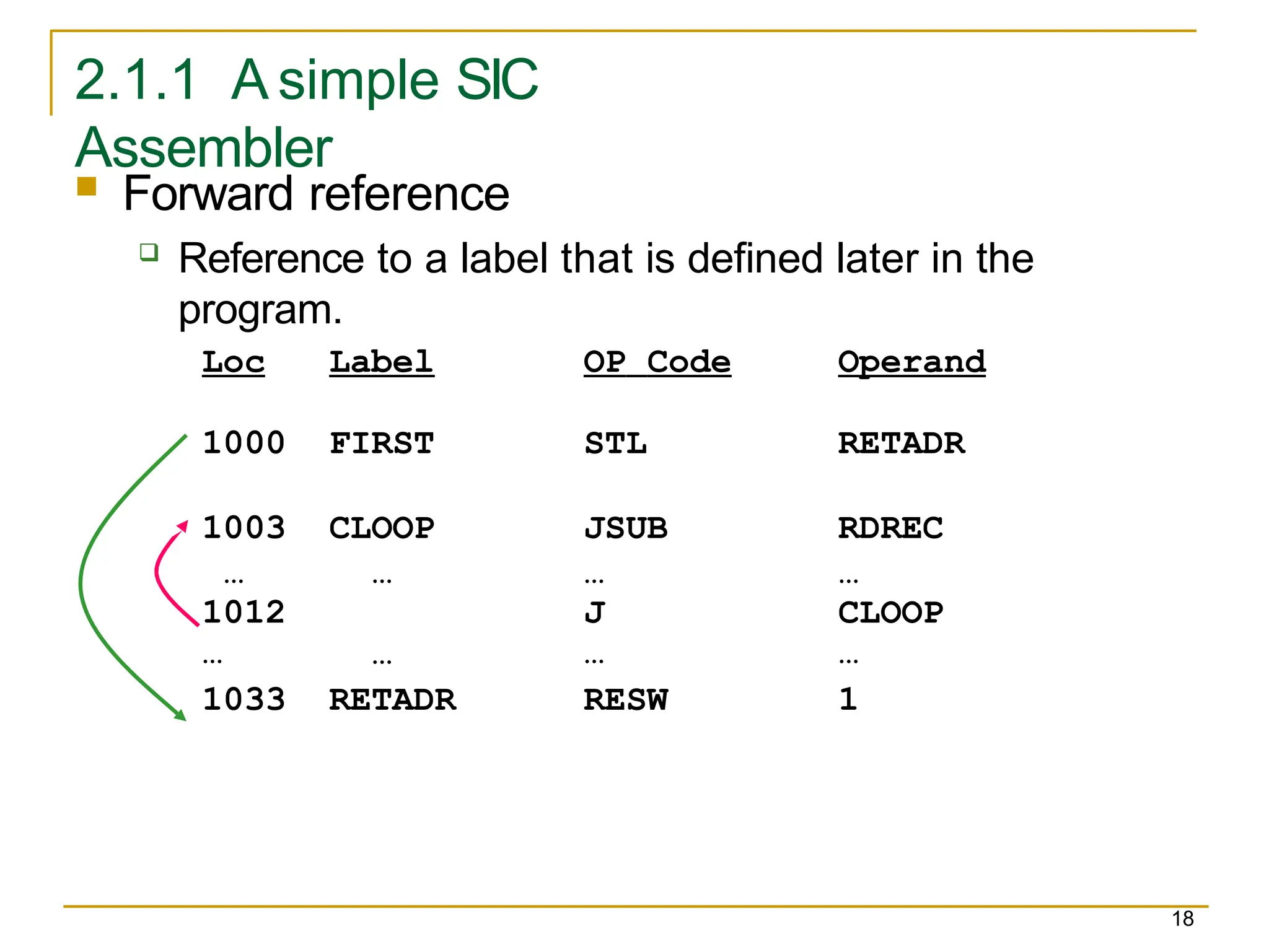
A forward reference
10 1000 FIRST STL
RETADR
141033
A reference to a label (RETADR) that is defined later
in the program
Most assemblers make two passes over the
source program
Most assemblers make two passes over
source program.
Pass 1 scans the source for label definitions
and assigns address (Loc).
Pass 2 performs most of the actual translation.
17.
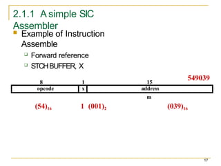
2.1.1 A simpleSIC
Assembler
17
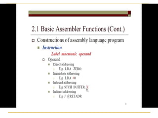
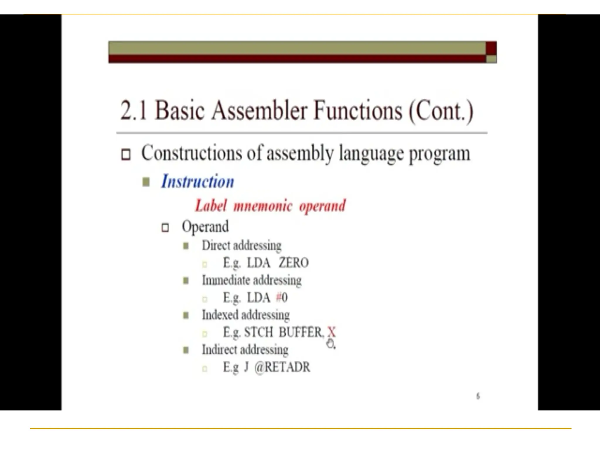
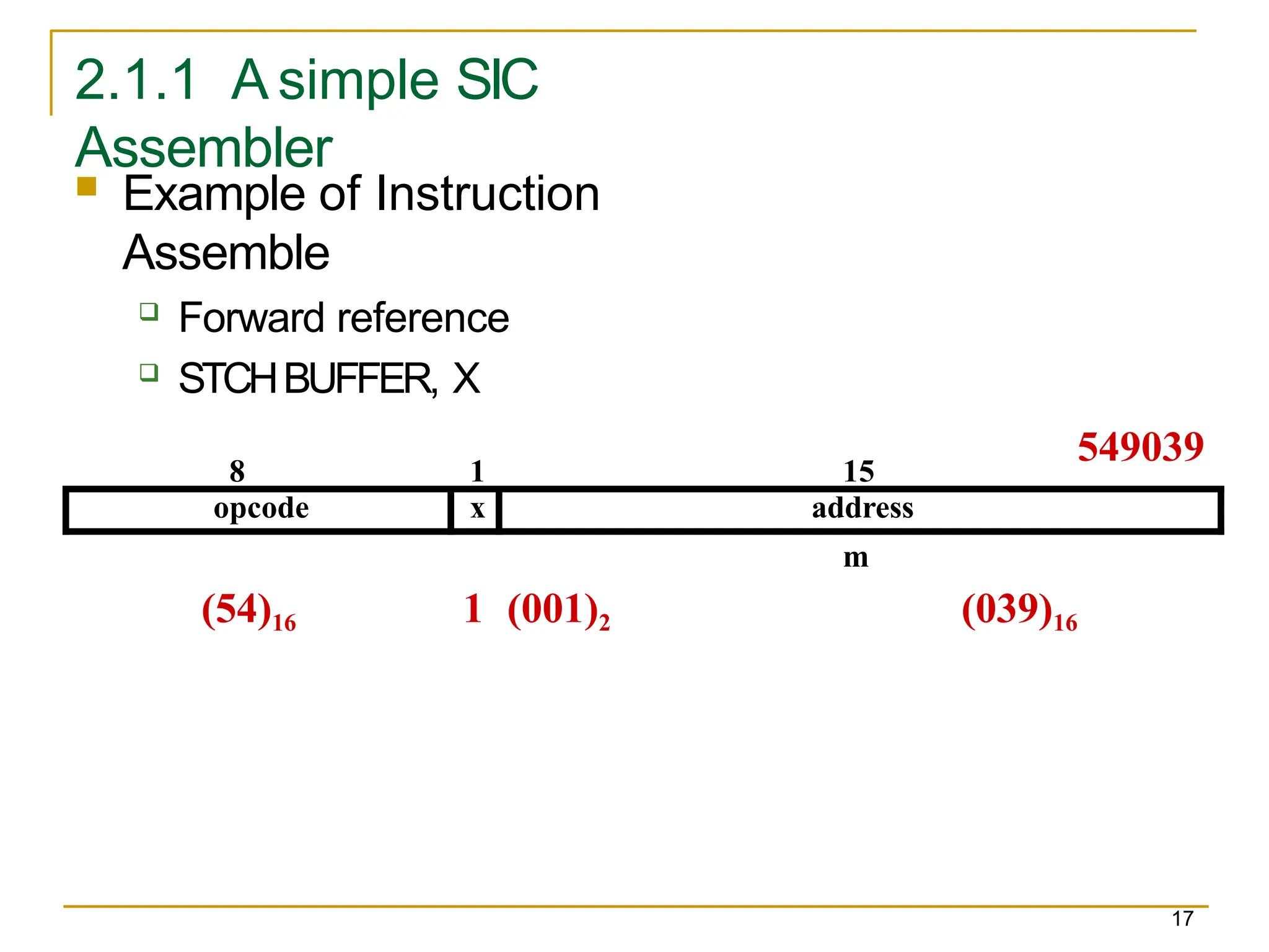
Example of Instruction
Assemble
Forward reference
STCHBUFFER, X
(54)16 1 (001)2 (039)16
8 1 15
m
opcode x address
549039
18.
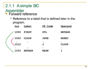
2.1.1 A simpleSIC
Assembler
Forward reference
Reference to a label that is defined later in the
program.
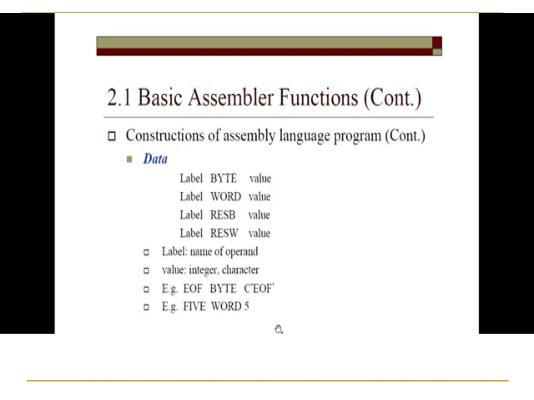
Loc Label OP Code Operand
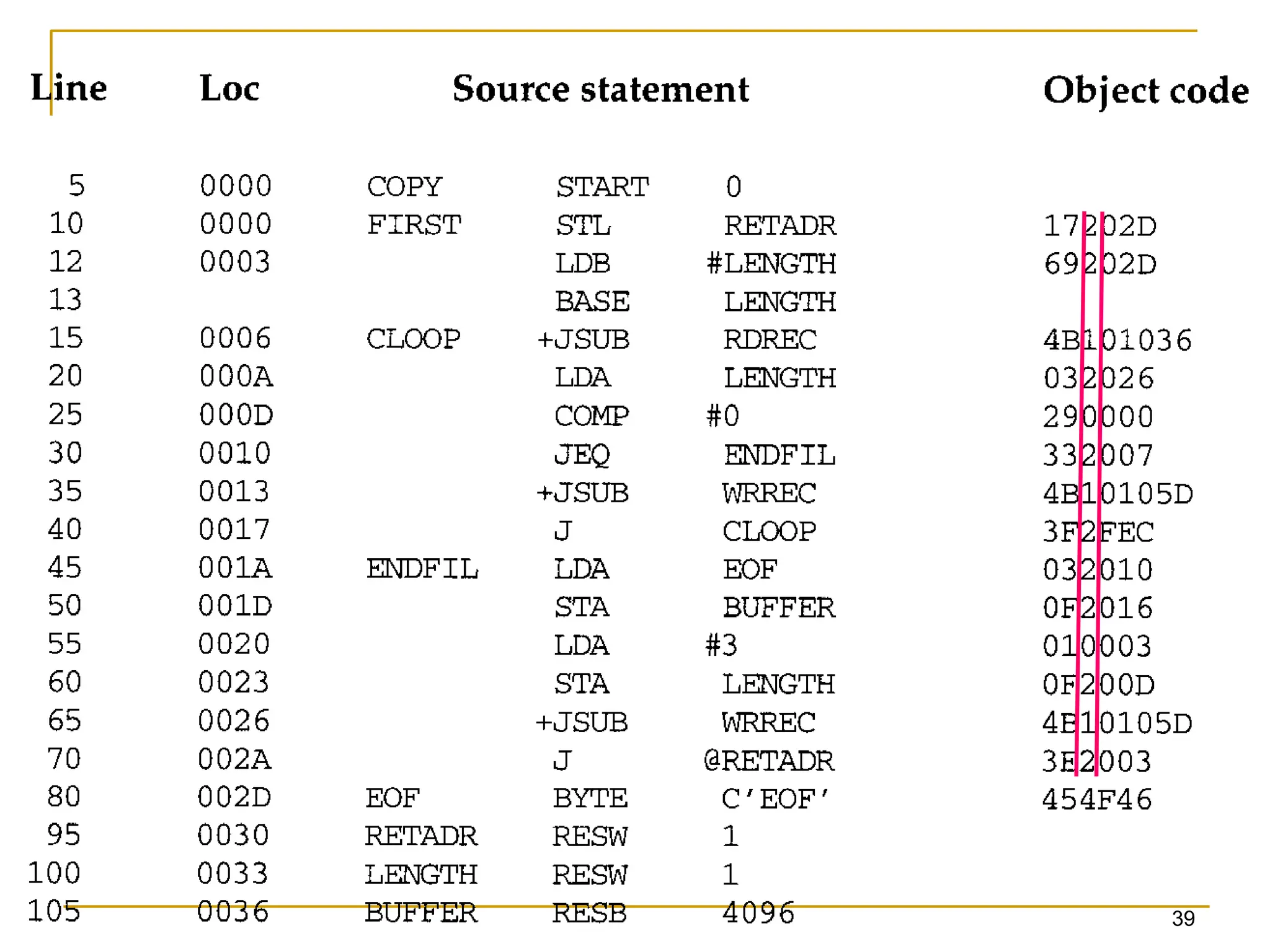
1000 FIRST STL RETADR
1003 CLOOP JSUB RDREC
…
1012
…
…
…
…
J
…
…
CLOOP
…
1033 RETADR RESW 1
18
19.
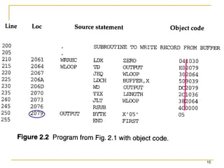
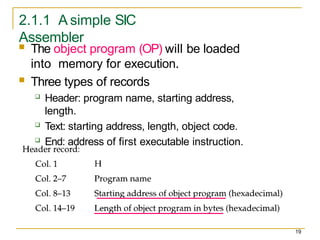
2.1.1 A simpleSIC
Assembler
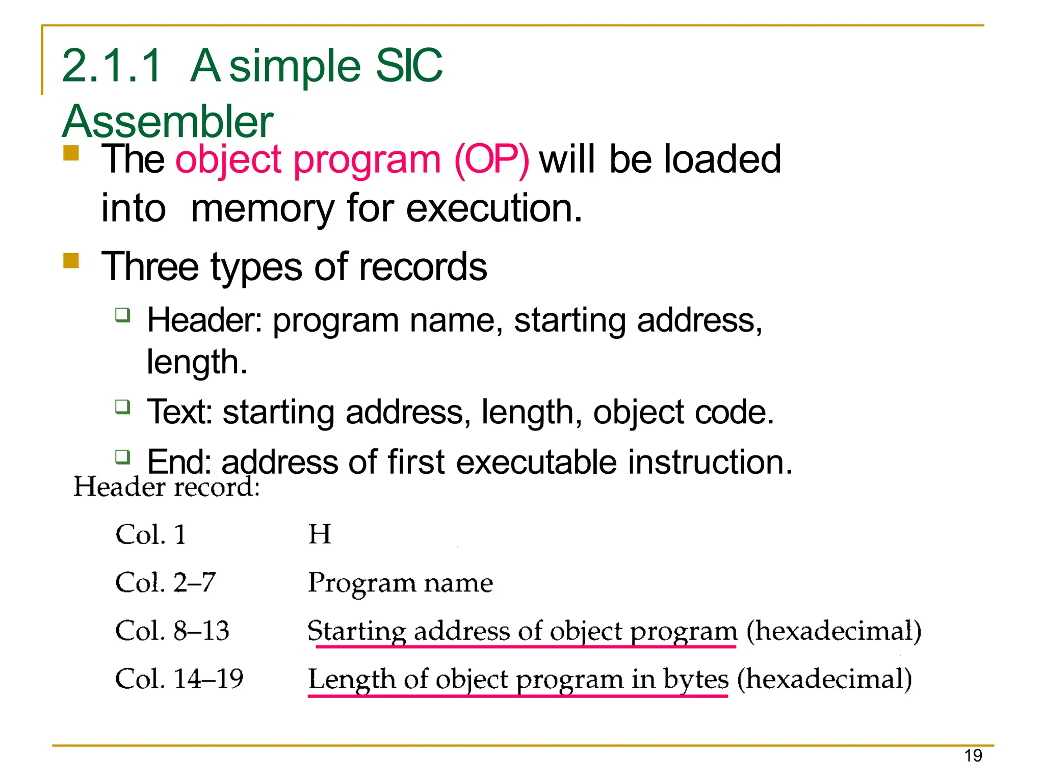
The object program (OP) will be loaded
into memory for execution.
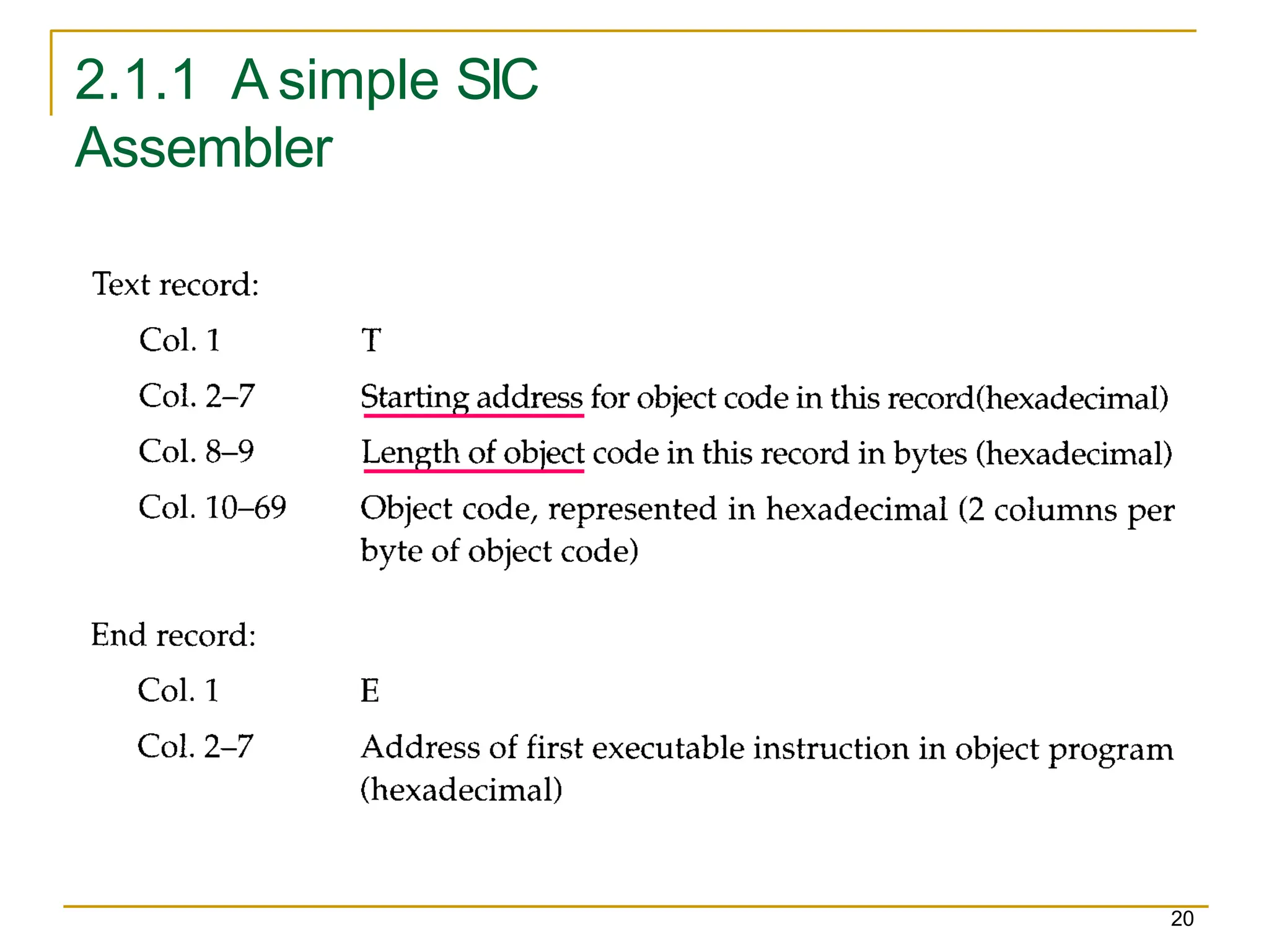
Three types of records
Header: program name, starting address,
length.
Text: starting address, length, object code.
End: address of first executable instruction.
19
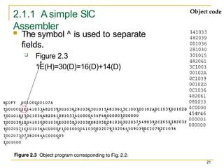
2.1.1 A simpleSIC
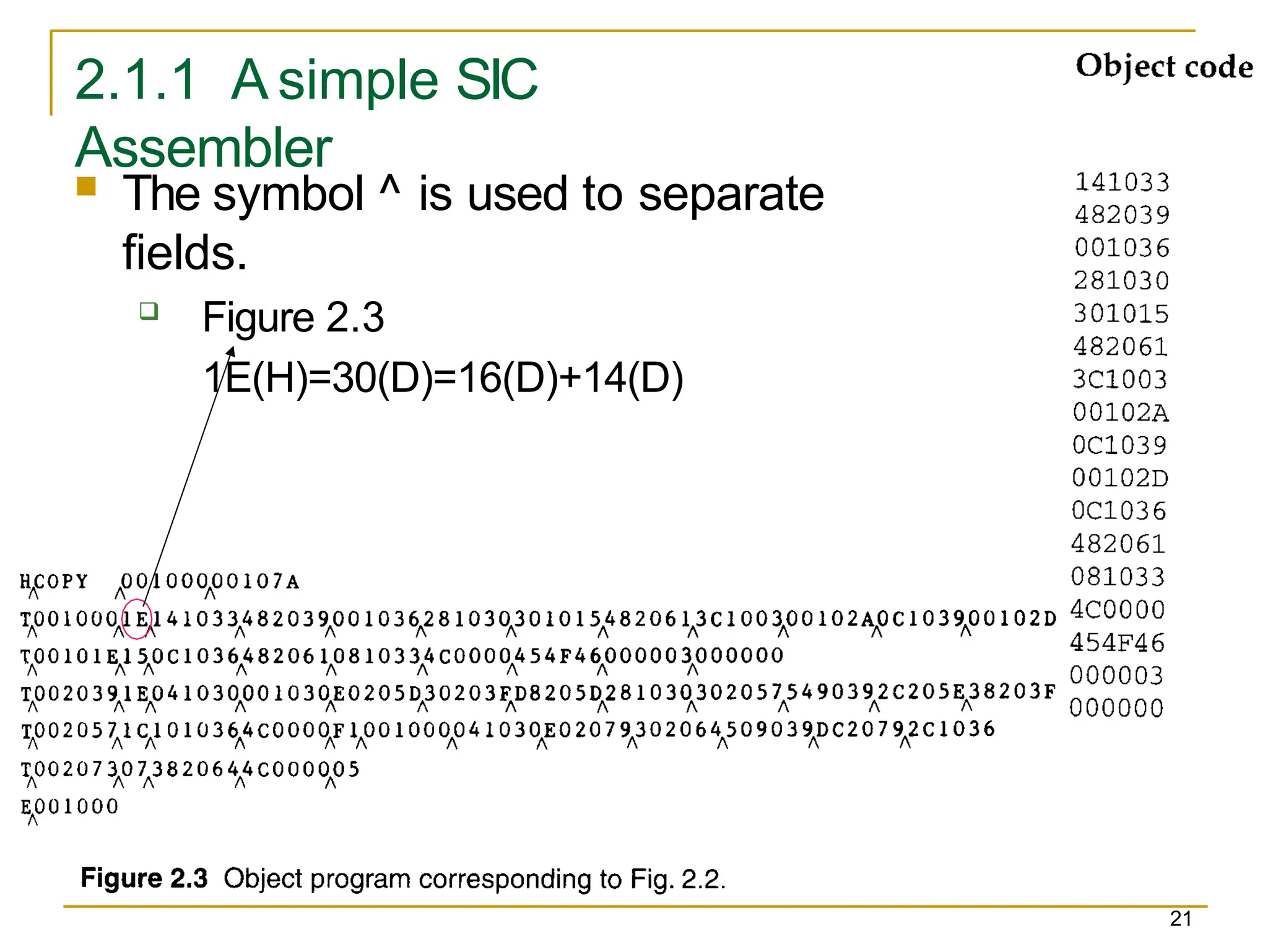
Assembler
The symbol ^ is used to separate
fields.
Figure 2.3
1E(H)=30(D)=16(D)+14(D)
21
22.
2.1.1 A simpleSIC
Assembler
22
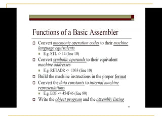
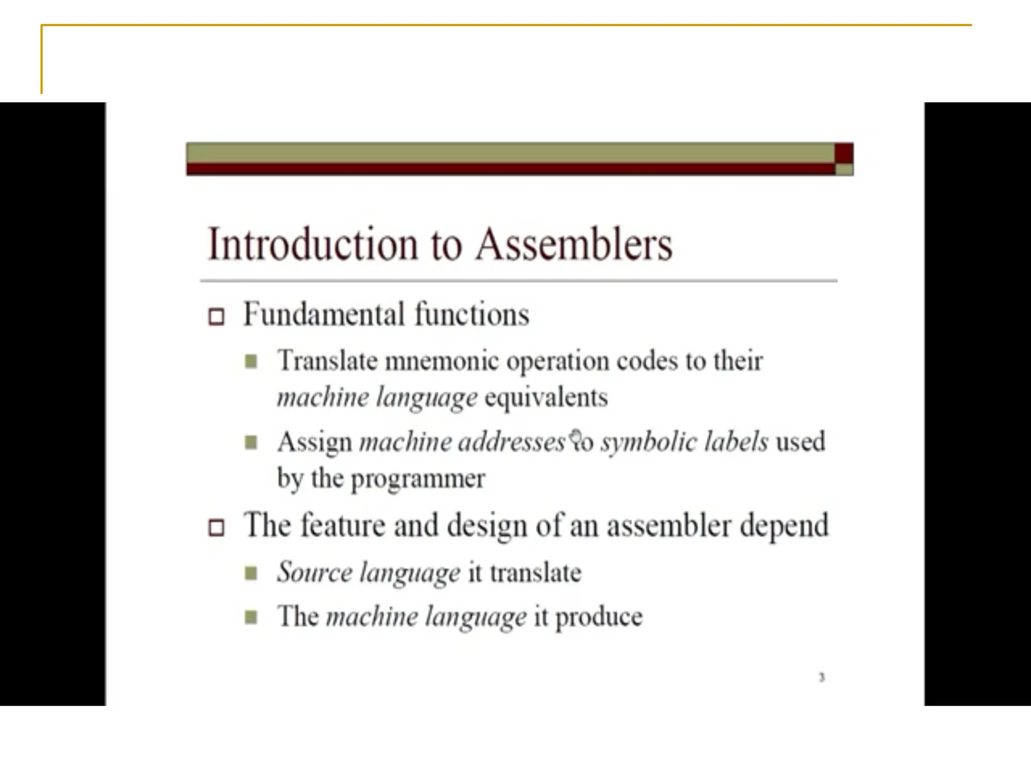
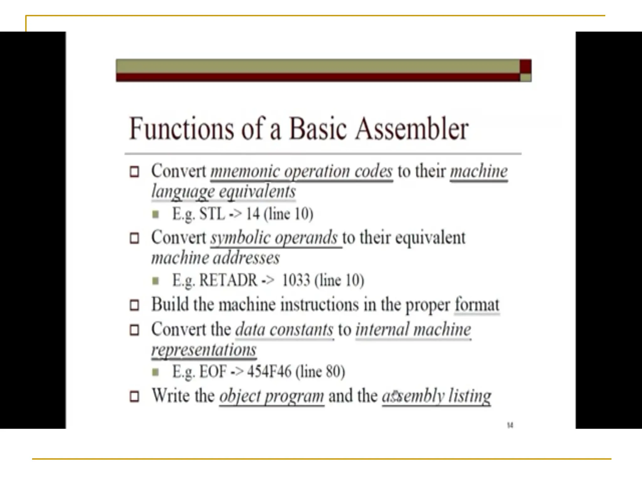
Assembler’s Functions
Convert mnemonic operation codes to their
machine language equivalents
STLto 14
Convert symbolic operands (referred label) to
their equivalent machine addresses
RETADR to 1033
Build the machine instructions in the proper
format
Convert the data constants to internal
machine representations
Write the object program and the assembly
listing
23.
20
2.1.1 A simpleSIC
Assembler
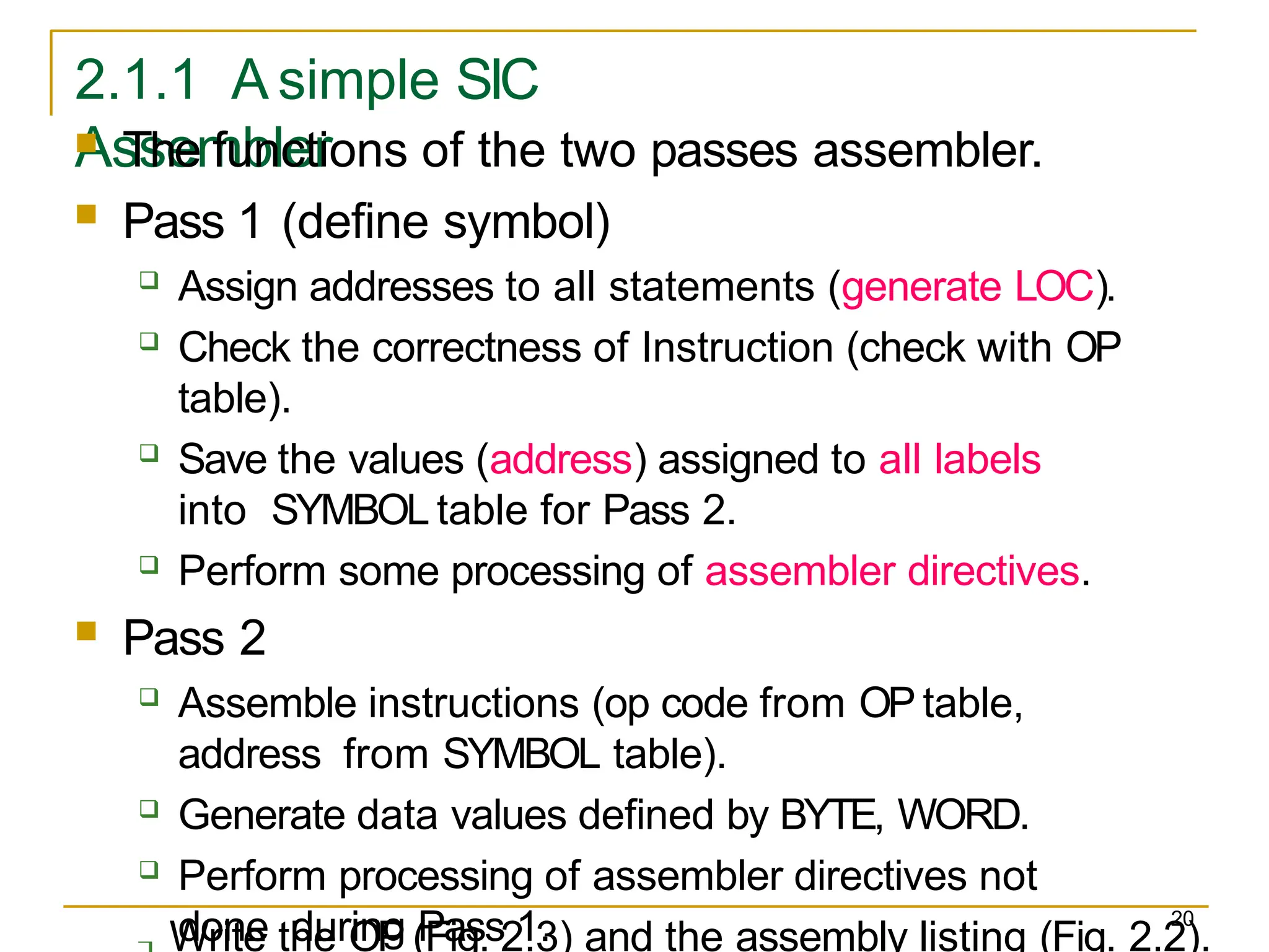
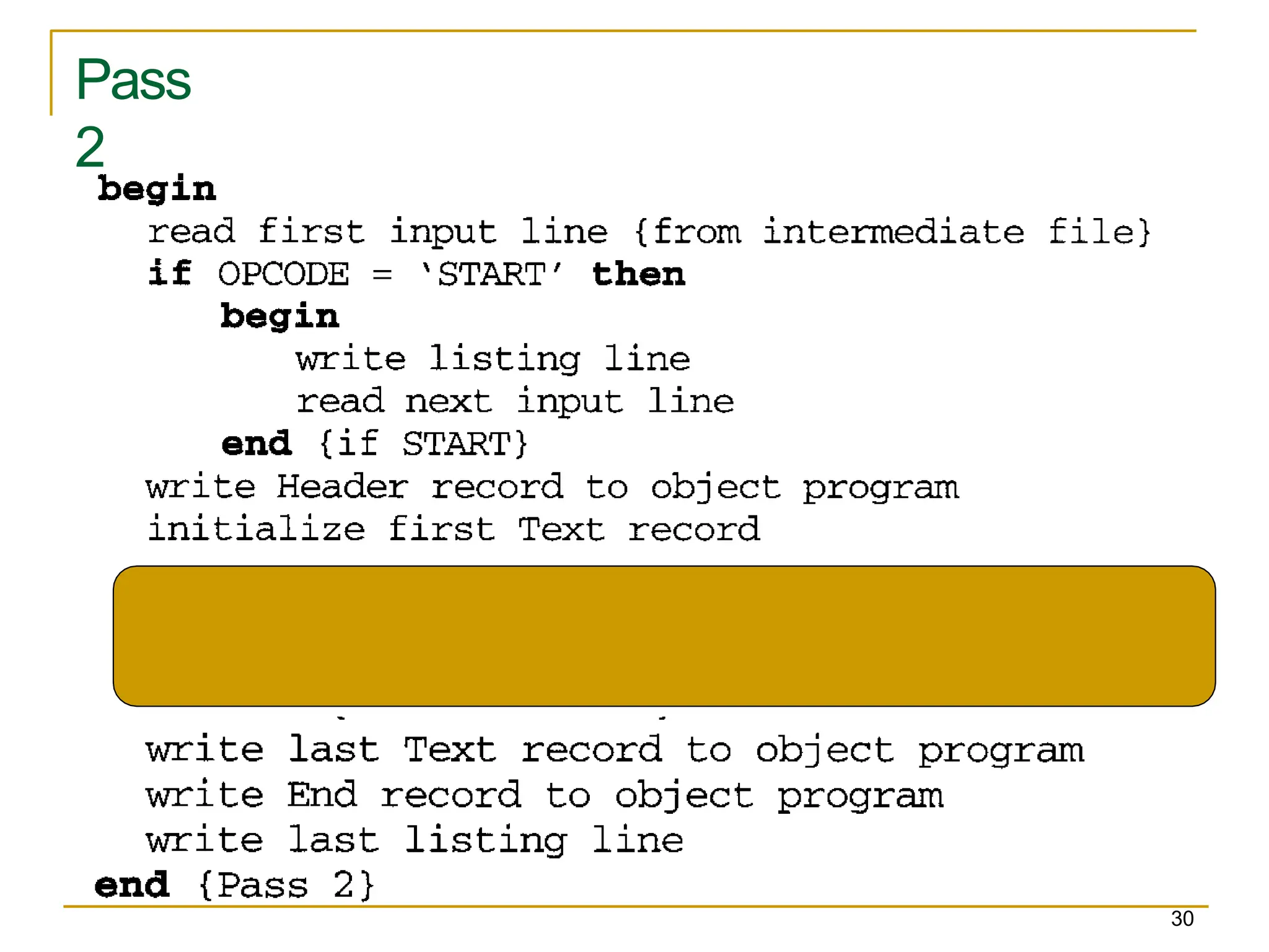
Write the OP (Fig. 2.3) and the assembly listing (Fig. 2.2).
The functions of the two passes assembler.
Pass 1 (define symbol)
Assign addresses to all statements (generate LOC).
Check the correctness of Instruction (check with OP
table).
Save the values (address) assigned to all labels
into SYMBOL table for Pass 2.
Perform some processing of assembler directives.
Pass 2
Assemble instructions (op code from OP table,
address from SYMBOL table).
Generate data values defined by BYTE, WORD.
Perform processing of assembler directives not
done during Pass 1.
24.
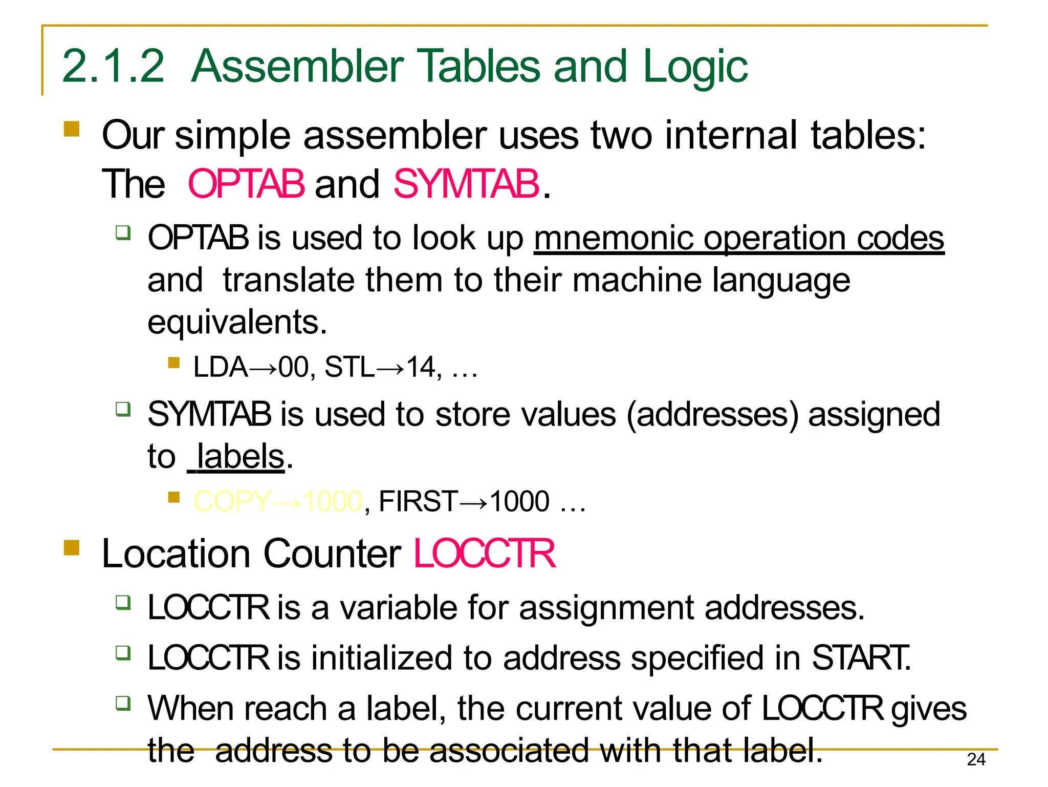
2.1.2 Assembler Tablesand Logic
24
Our simple assembler uses two internal tables:
The OPTAB and SYMTAB.
OPTAB is used to look up mnemonic operation codes
and translate them to their machine language
equivalents.
LDA→00, STL→14, …
SYMTAB is used to store values (addresses) assigned
to labels.
COPY→1000, FIRST→1000 …
Location Counter LOCCTR
LOCCTR is a variable for assignment addresses.
LOCCTR is initialized to address specified in START
.
When reach a label, the current value of LOCCTR gives
the address to be associated with that label.
25.
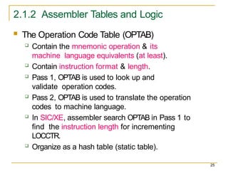
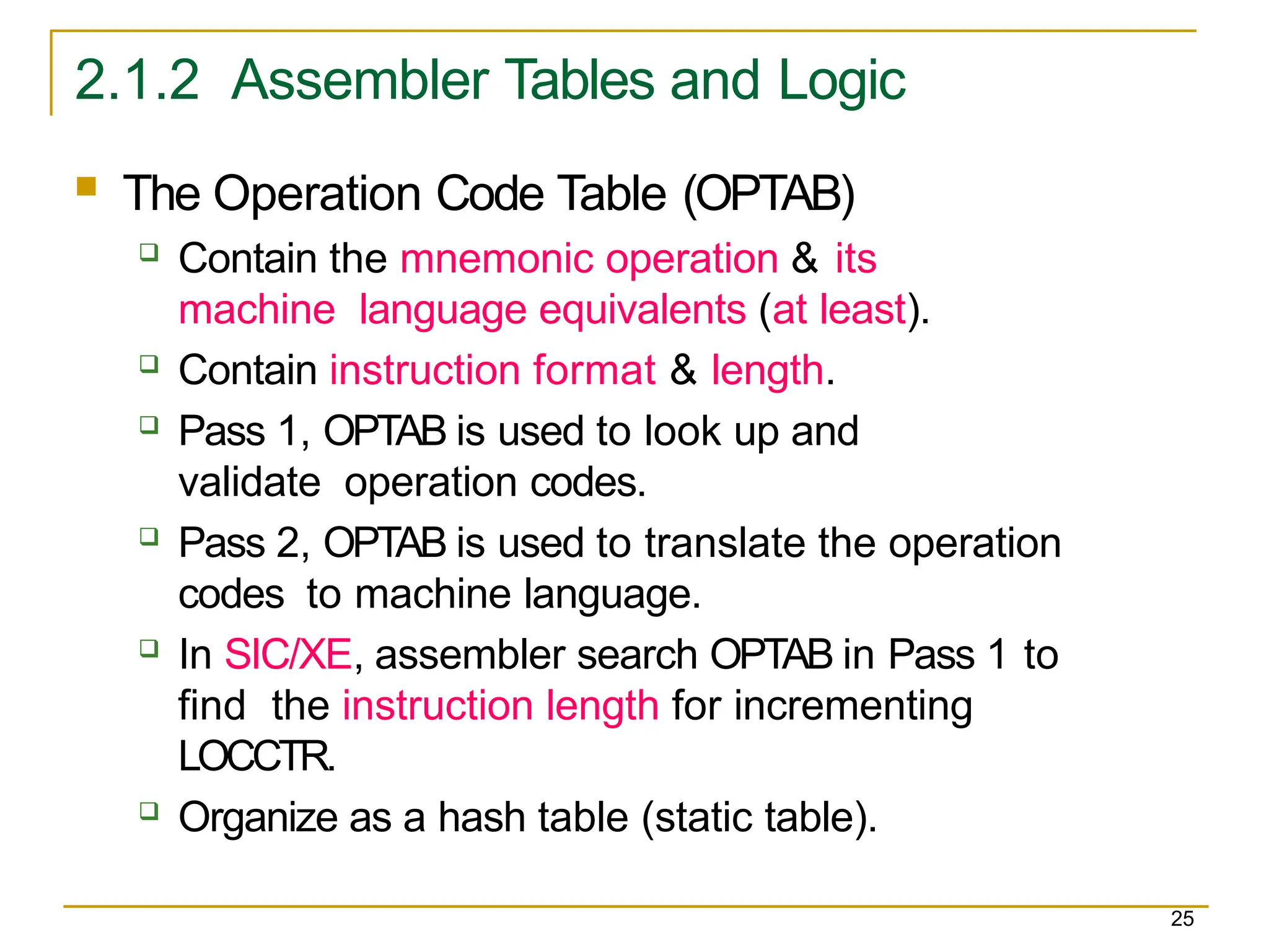
2.1.2 Assembler Tablesand Logic
25
The Operation Code Table (OPTAB)
Contain the mnemonic operation & its
machine language equivalents (at least).
Contain instruction format & length.
Pass 1, OPTAB is used to look up and
validate operation codes.
Pass 2, OPTAB is used to translate the operation
codes to machine language.
In SIC/XE, assembler search OPTAB in Pass 1 to
find the instruction length for incrementing
LOCCTR.
Organize as a hash table (static table).
26.
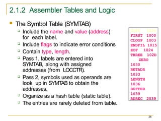
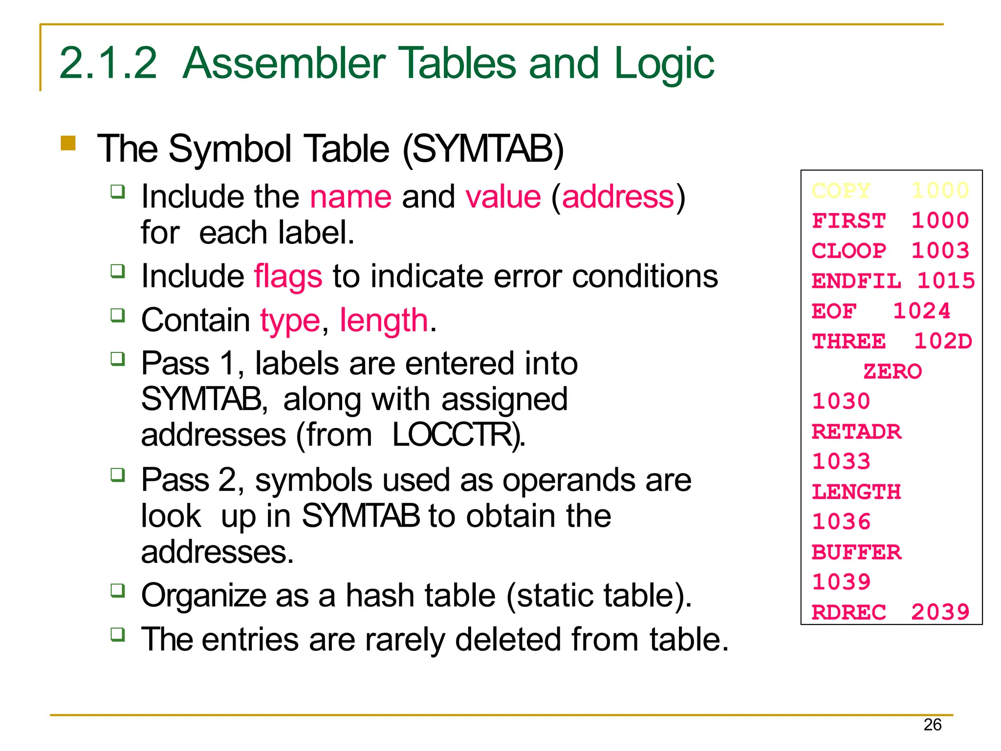
2.1.2 Assembler Tablesand Logic
26
The Symbol Table (SYMTAB)
Include the name and value (address)
for each label.
Include flags to indicate error conditions
Contain type, length.
Pass 1, labels are entered into
SYMTAB, along with assigned
addresses (from LOCCTR).
Pass 2, symbols used as operands are
look up in SYMTAB to obtain the
addresses.
Organize as a hash table (static table).
The entries are rarely deleted from table.
COPY 1000
FIRST 1000
CLOOP 1003
ENDFIL 1015
EOF 1024
THREE 102D
ZERO
1030
RETADR
1033
LENGTH
1036
BUFFER
1039
RDREC 2039
27.
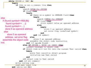
2.1.2 Assembler Tablesand Logic
27
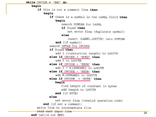
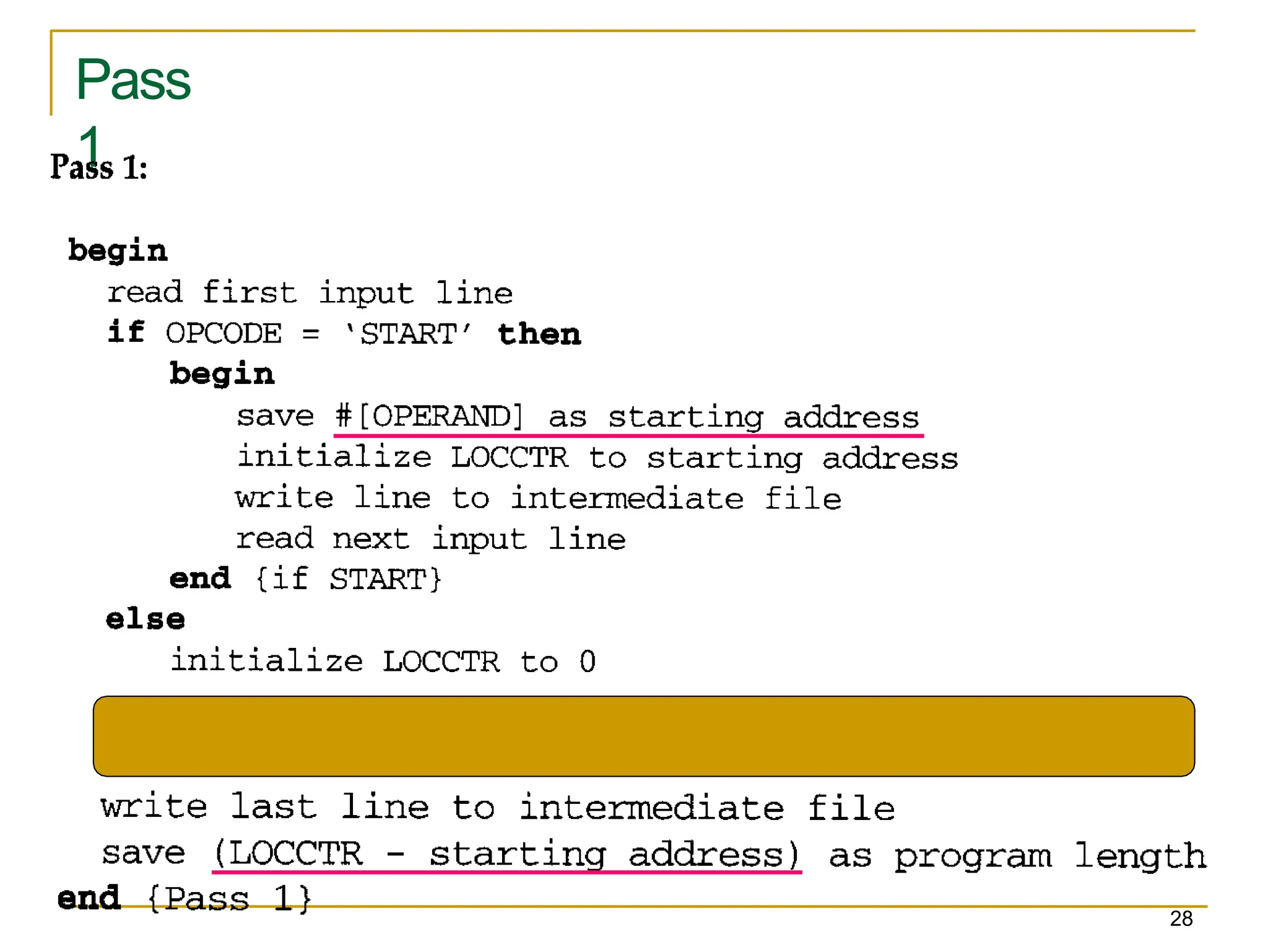
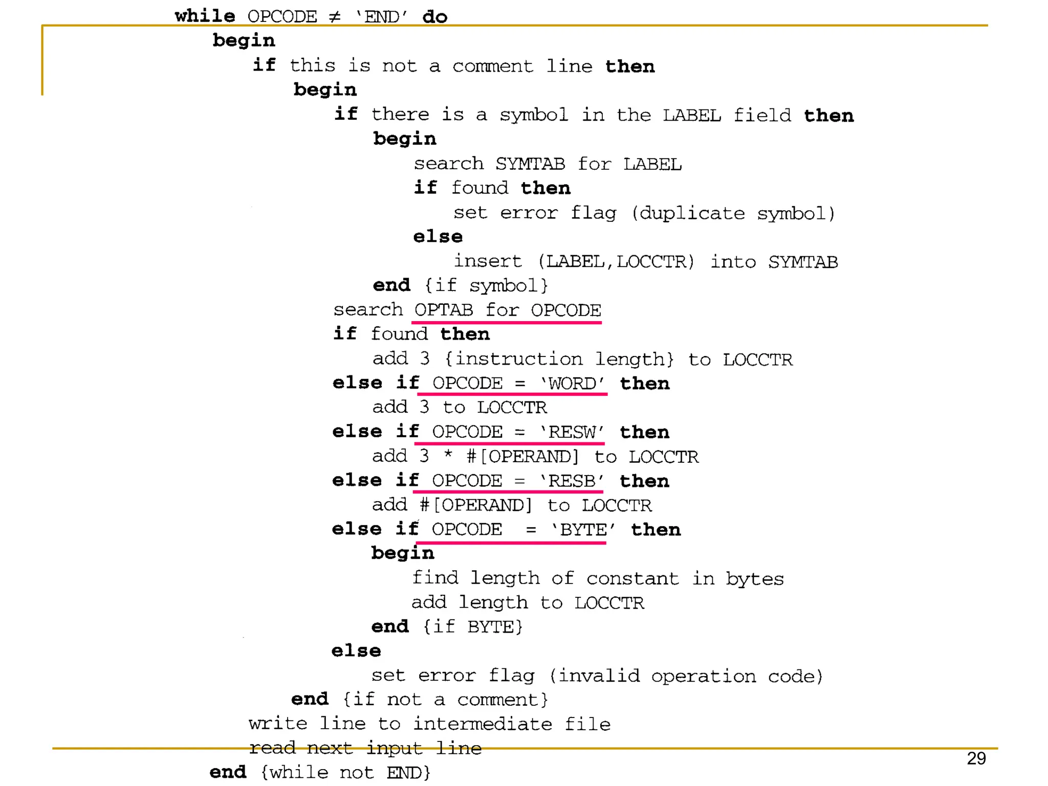
Pass 1 usually writes an intermediate file.
Contain source statement together with its
assigned address, error indicators.
This file is used as input to Pass 2.
Figure 2.4 shows the two passes of assembler.
Format with fields LABEL, OPCODE, and
OPERAND.
Denote numeric value with the prefix
#. #[OPERAND]
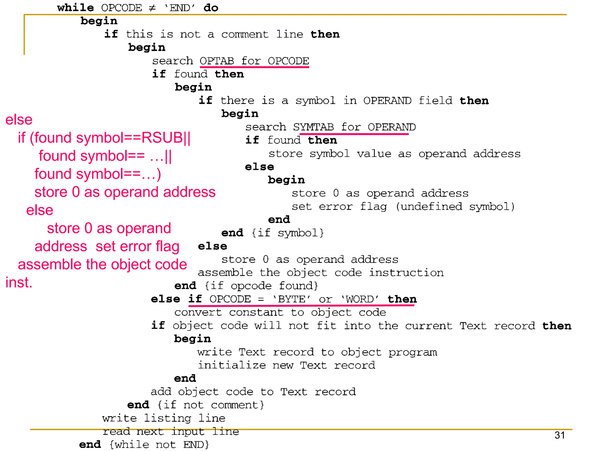
else
if (found symbol==RSUB||
foundsymbol== …||
found symbol==…)
store 0 as operand address
else
store 0 as operand
address set error flag
assemble the object code
inst.
31
32.
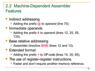
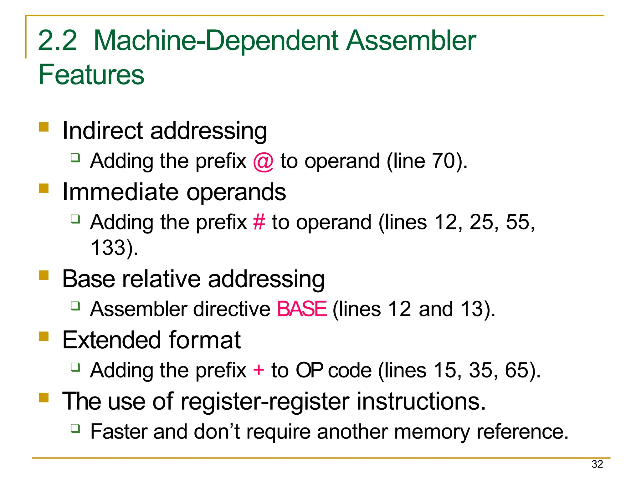
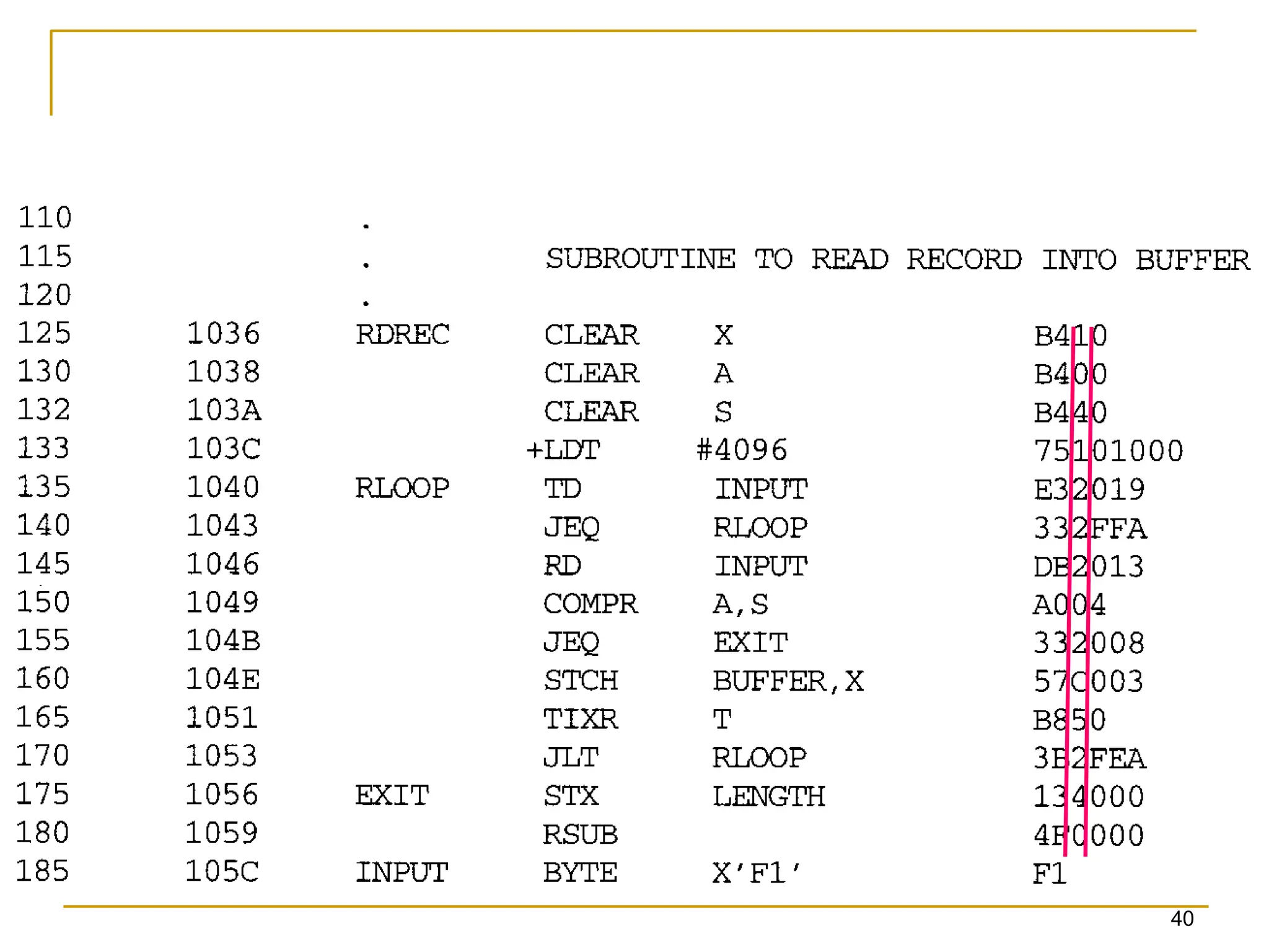
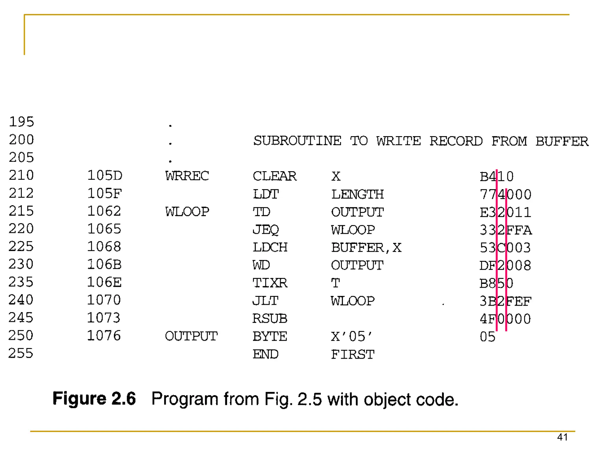
2.2 Machine-Dependent Assembler
Features
32
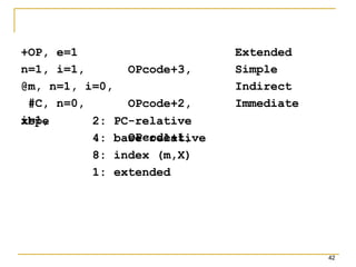
Indirect addressing
Adding the prefix @ to operand (line 70).
Immediate operands
Adding the prefix # to operand (lines 12, 25, 55,
133).
Base relative addressing
Assembler directive BASE (lines 12 and 13).
Extended format
Adding the prefix + to OP code (lines 15, 35, 65).
The use of register-register instructions.
Faster and don’t require another memory reference.
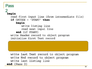
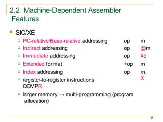
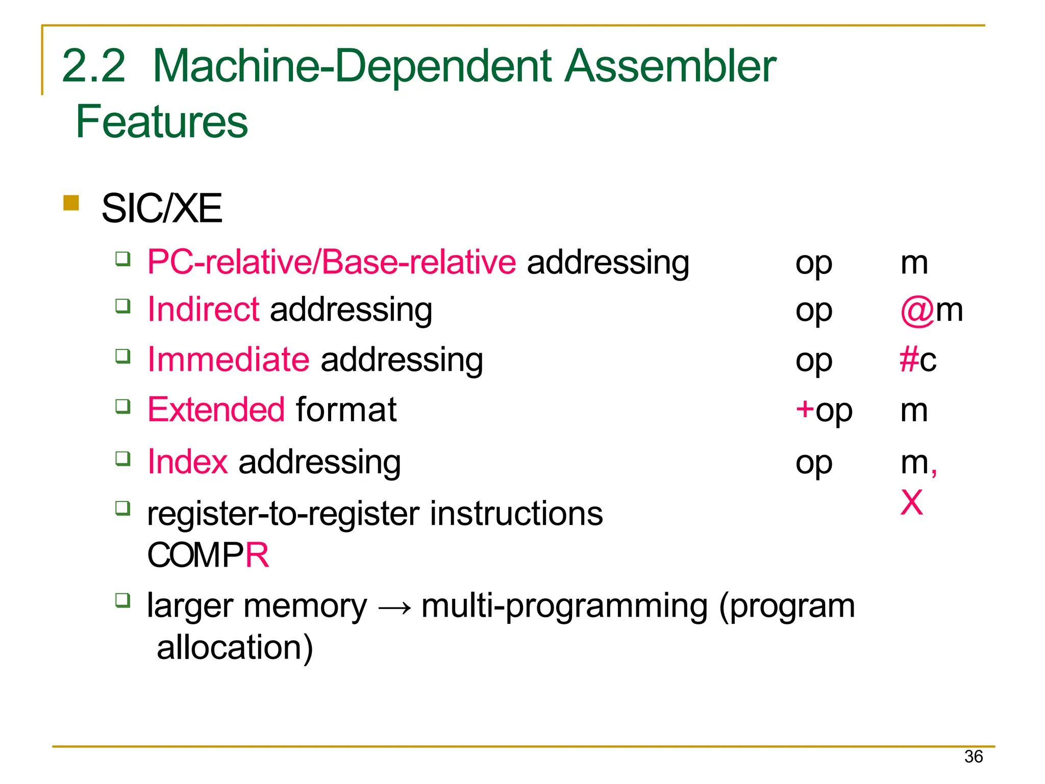
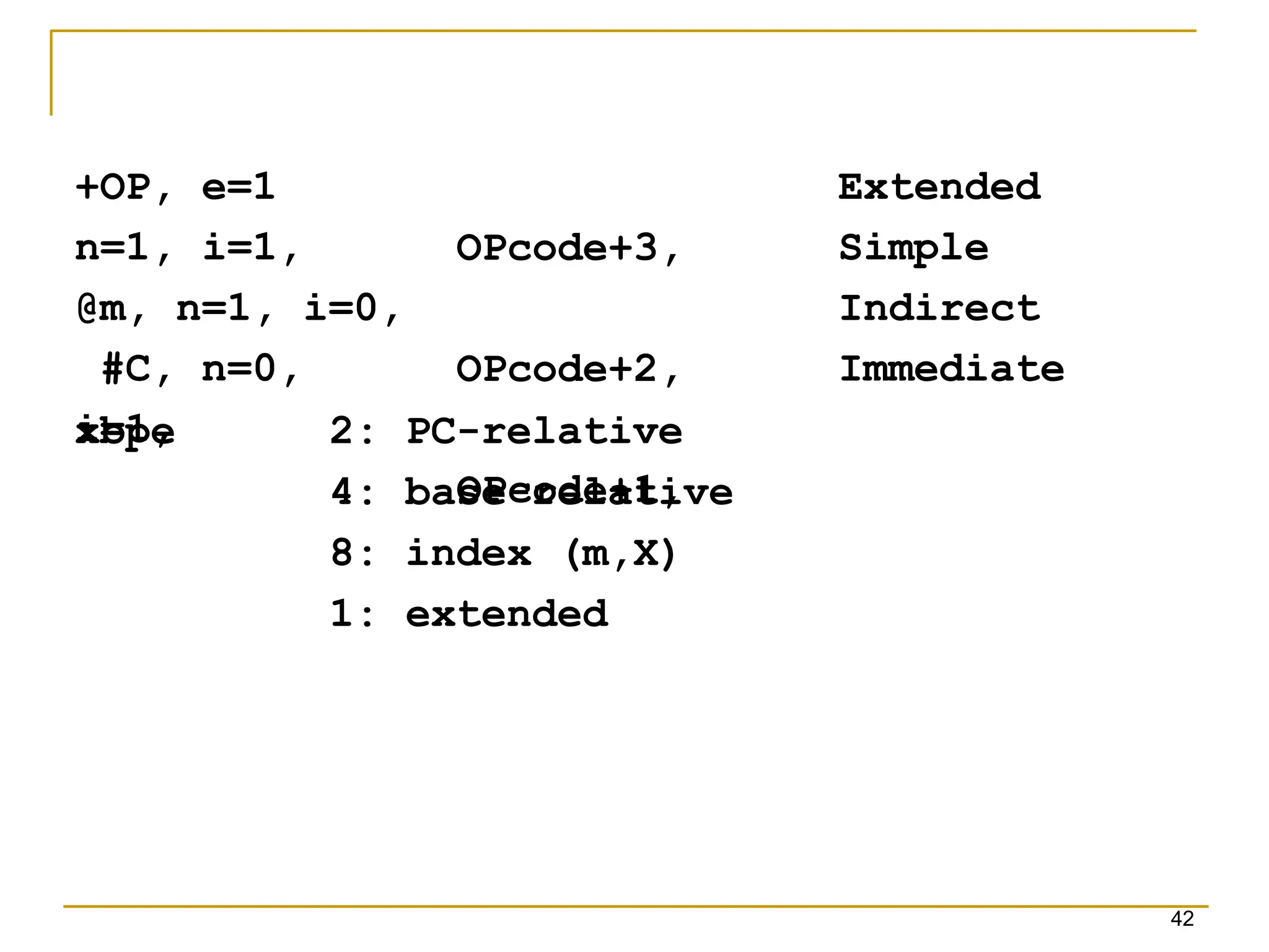
2.2 Machine-Dependent Assembler
Features
36
SIC/XE
PC-relative/Base-relative addressing op m
Indirect addressing op @m
Immediate addressing op #c
Extended format +op m
Index addressing op m,
X
register-to-register instructions
COMPR
larger memory → multi-programming (program
allocation)
37.
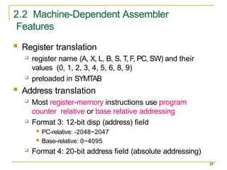
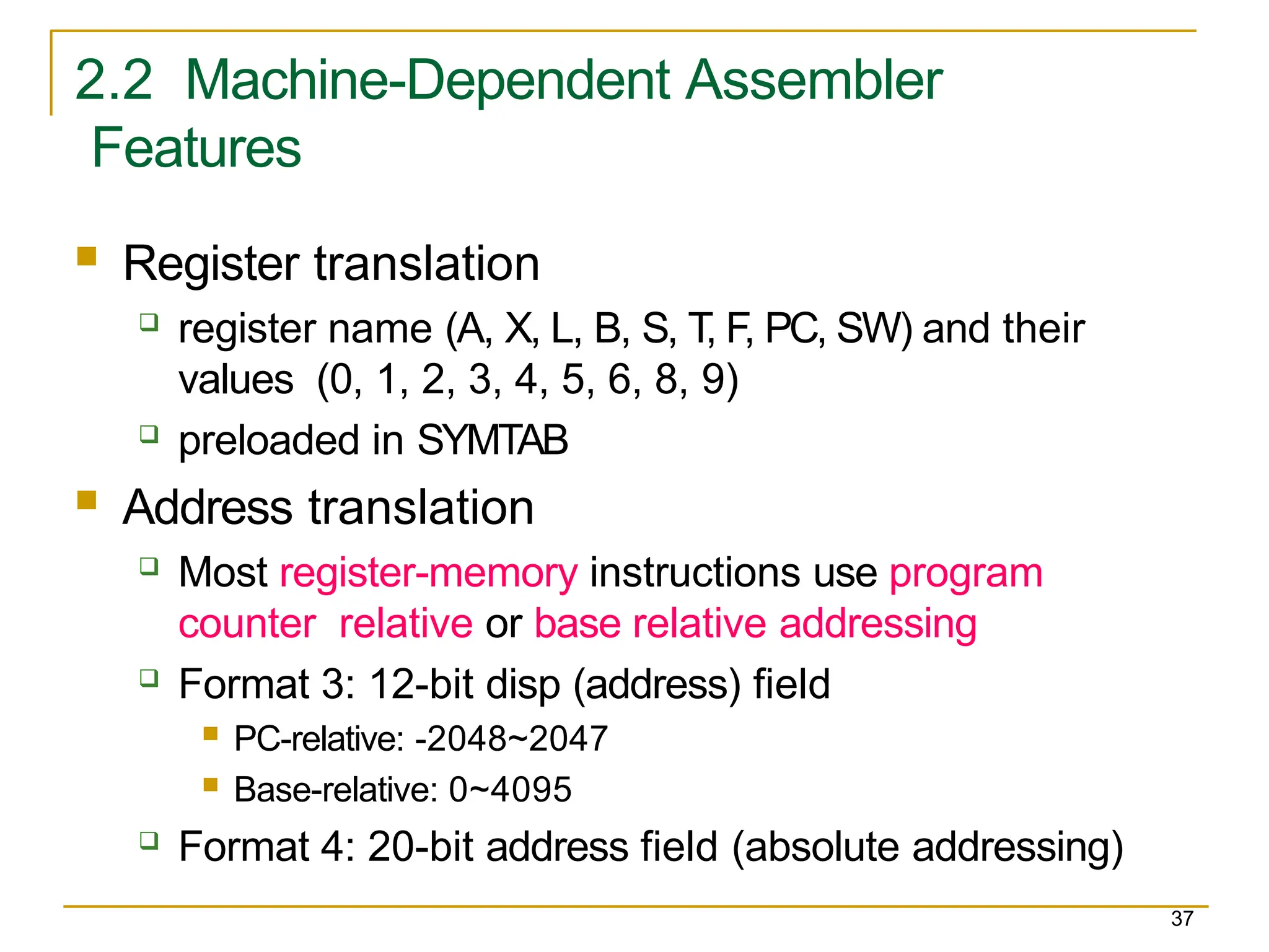
2.2 Machine-Dependent Assembler
Features
37
Register translation
register name (A, X, L, B, S, T, F, PC, SW) and their
values (0, 1, 2, 3, 4, 5, 6, 8, 9)
preloaded in SYMTAB
Address translation
Most register-memory instructions use program
counter relative or base relative addressing
Format 3: 12-bit disp (address) field
PC-relative: -2048~2047
Base-relative: 0~4095
Format 4: 20-bit address field (absolute addressing)
38.
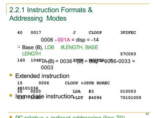
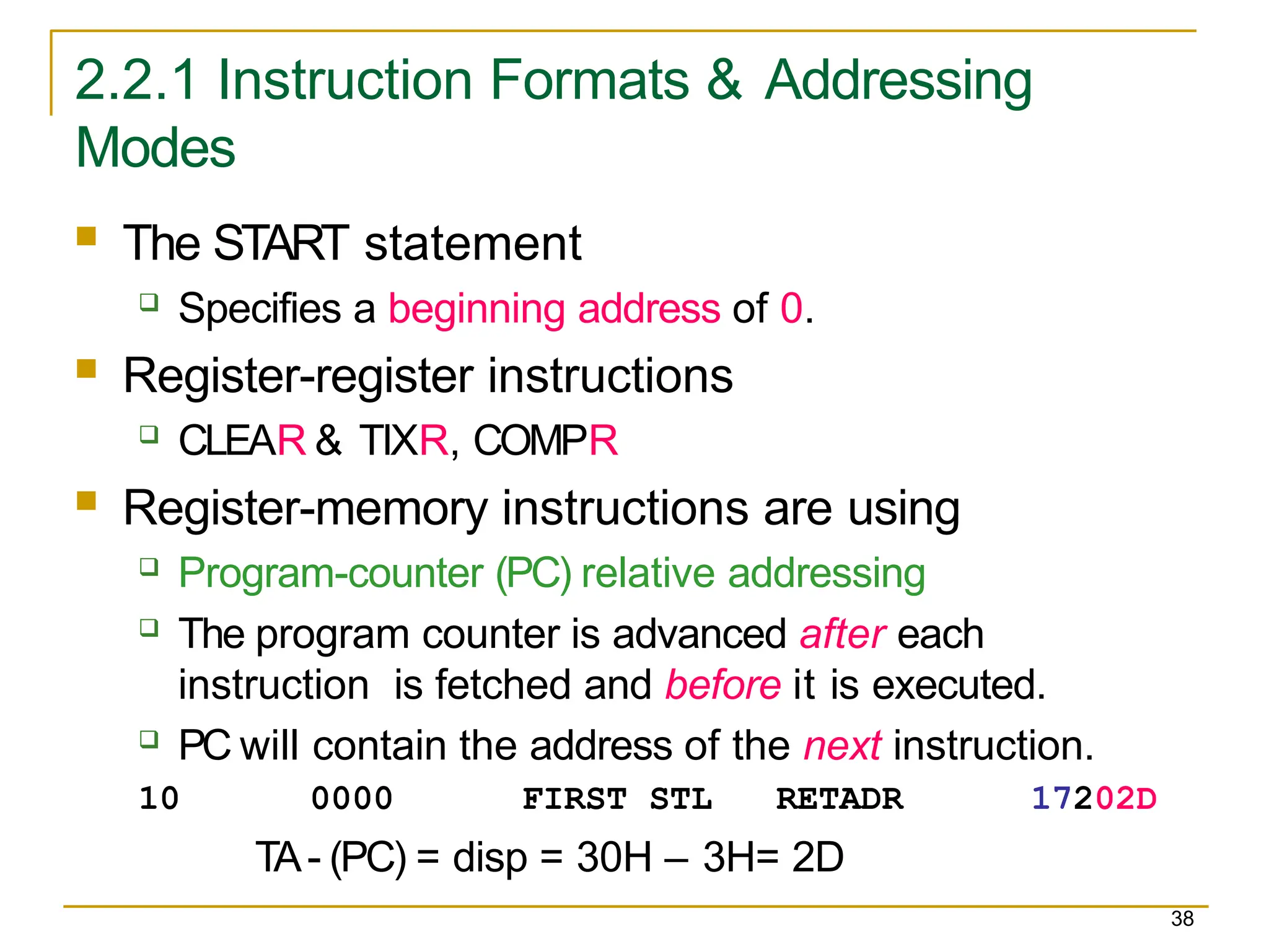
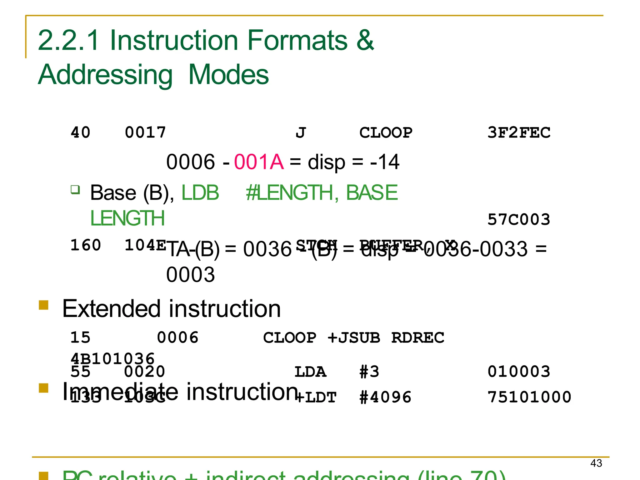
2.2.1 Instruction Formats& Addressing
Modes
38
The START statement
Specifies a beginning address of 0.
Register-register instructions
CLEAR & TIXR, COMPR
Register-memory instructions are using
Program-counter (PC) relative addressing
The program counter is advanced after each
instruction is fetched and before it is executed.
PC will contain the address of the next instruction.
10 0000 FIRST STL RETADR 17202D
TA- (PC) = disp = 30H – 3H= 2D
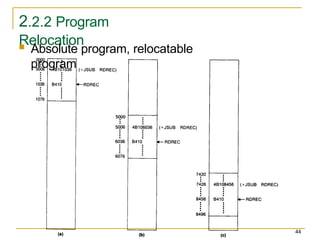
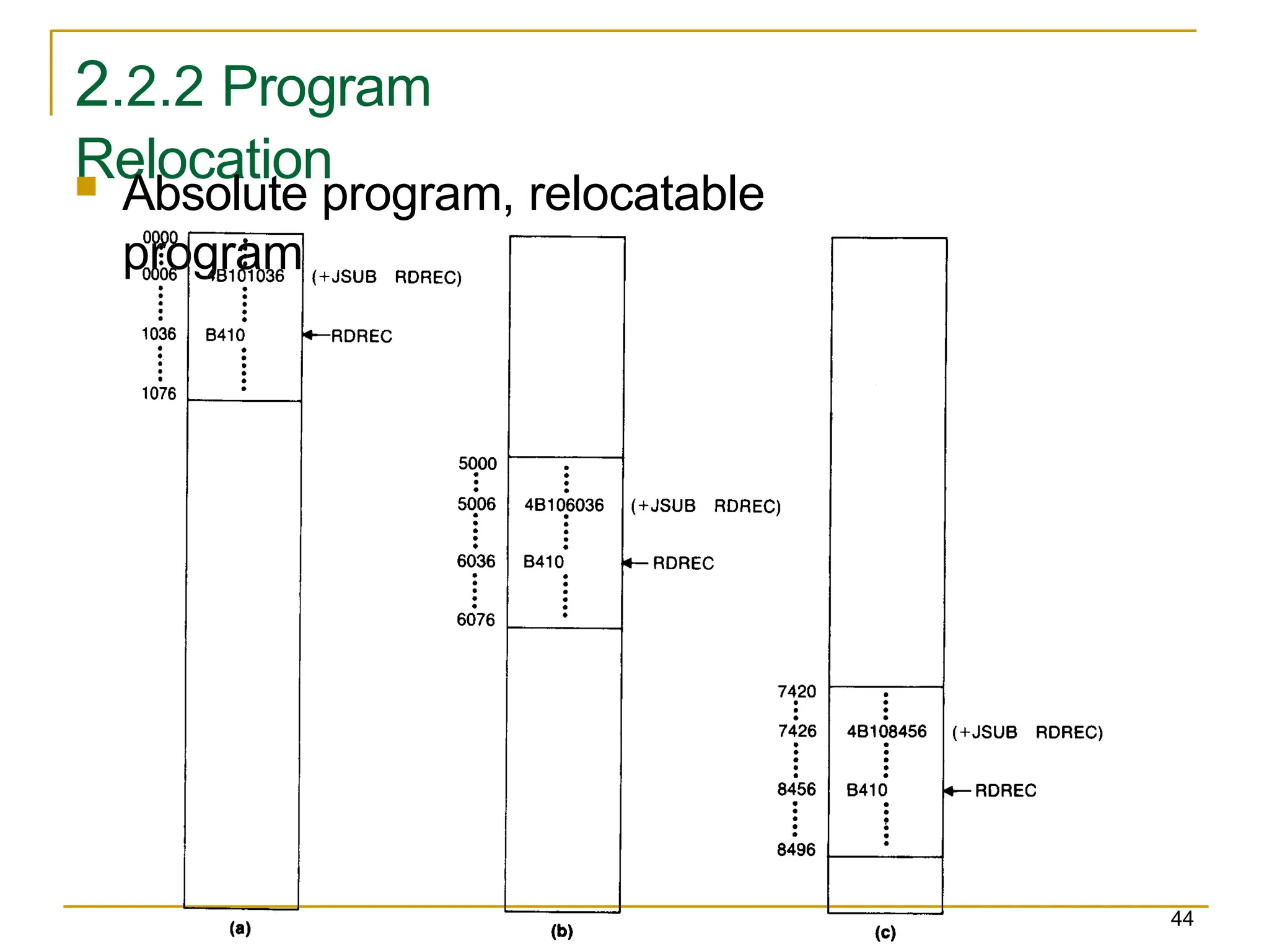
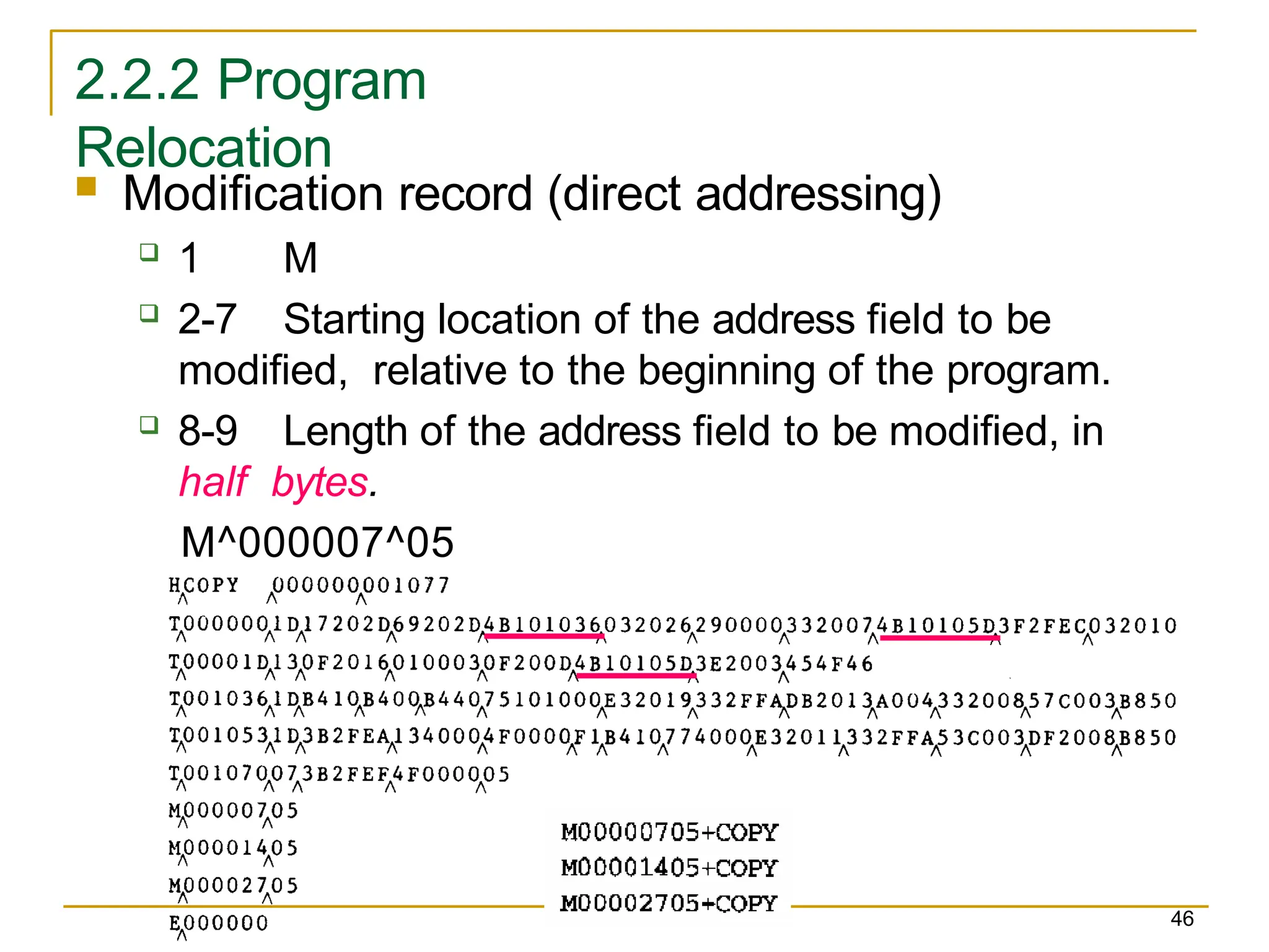
2.2.2 Program
Relocation
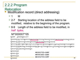
Modificationrecord (direct addressing)
1 M
2-7 Starting location of the address field to be
modified, relative to the beginning of the program.
8-9 Length of the address field to be modified, in
half bytes.
M^000007^05
46
![2.1.2 Assembler Tables and Logic
27
Pass 1 usually writes an intermediate file.
Contain source statement together with its
assigned address, error indicators.
This file is used as input to Pass 2.
Figure 2.4 shows the two passes of assembler.
Format with fields LABEL, OPCODE, and
OPERAND.
Denote numeric value with the prefix
#. #[OPERAND]](https://image.slidesharecdn.com/assembler-250510150014-78c1c8ff/85/basic-assembler-functions-in-system-software-pptx-27-320.jpg)


![2.1.2 Assembler Tables and Logic
27
Pass 1 usually writes an intermediate file.
Contain source statement together with its
assigned address, error indicators.
This file is used as input to Pass 2.
Figure 2.4 shows the two passes of assembler.
Format with fields LABEL, OPCODE, and
OPERAND.
Denote numeric value with the prefix
#. #[OPERAND]](https://image.slidesharecdn.com/assembler-250510150014-78c1c8ff/75/basic-assembler-functions-in-system-software-pptx-27-2048.jpg)


![Chap03[1]](https://cdn.slidesharecdn.com/ss_thumbnails/chap031-140914002717-phpapp01-thumbnail.jpg?width=600ounds&width=560&fit=bounds)


