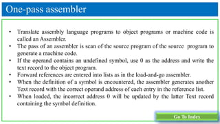
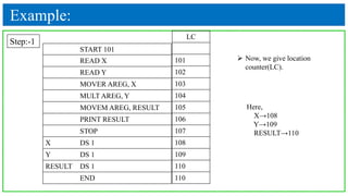
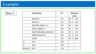
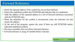
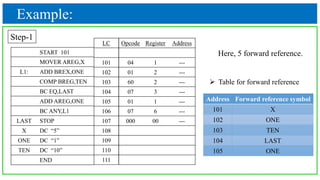
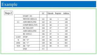
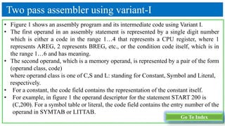
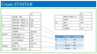
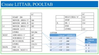
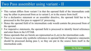
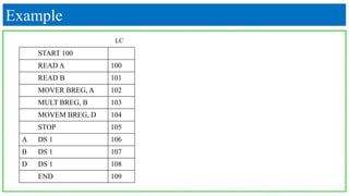
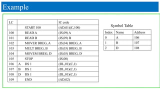
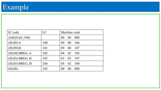
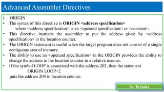
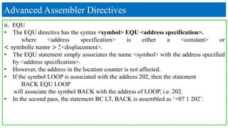
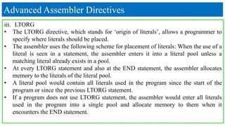
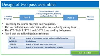
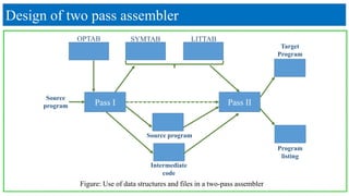
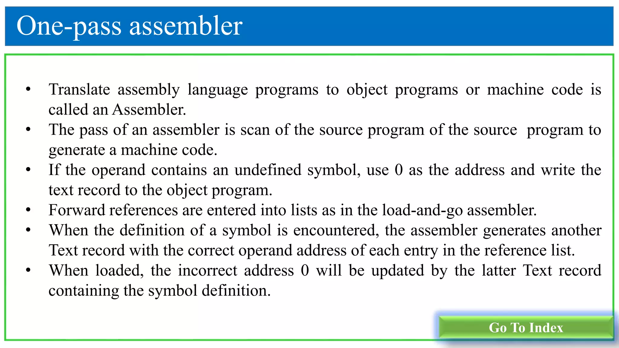
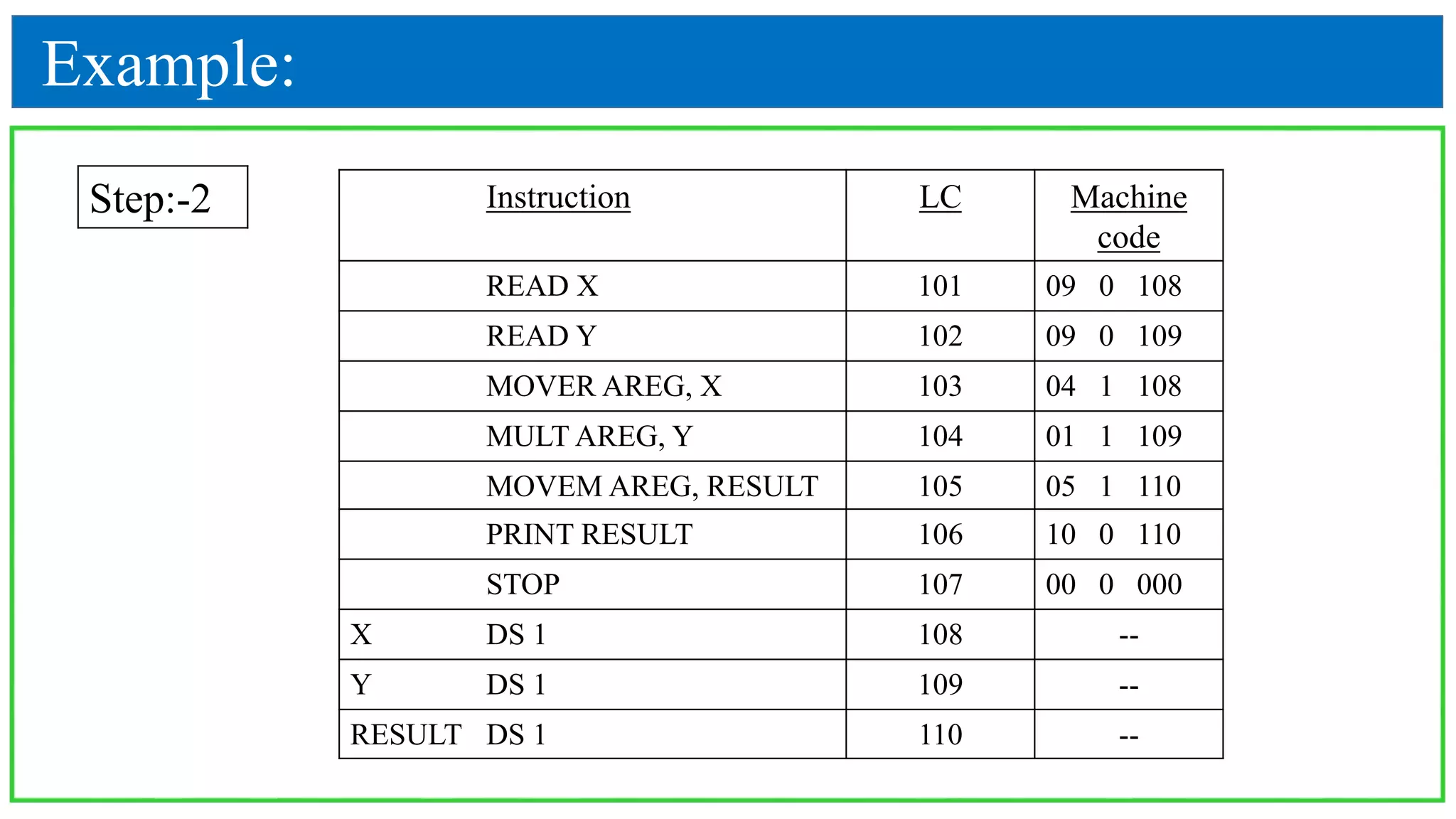
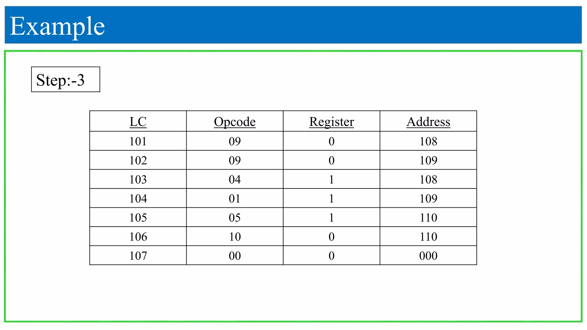
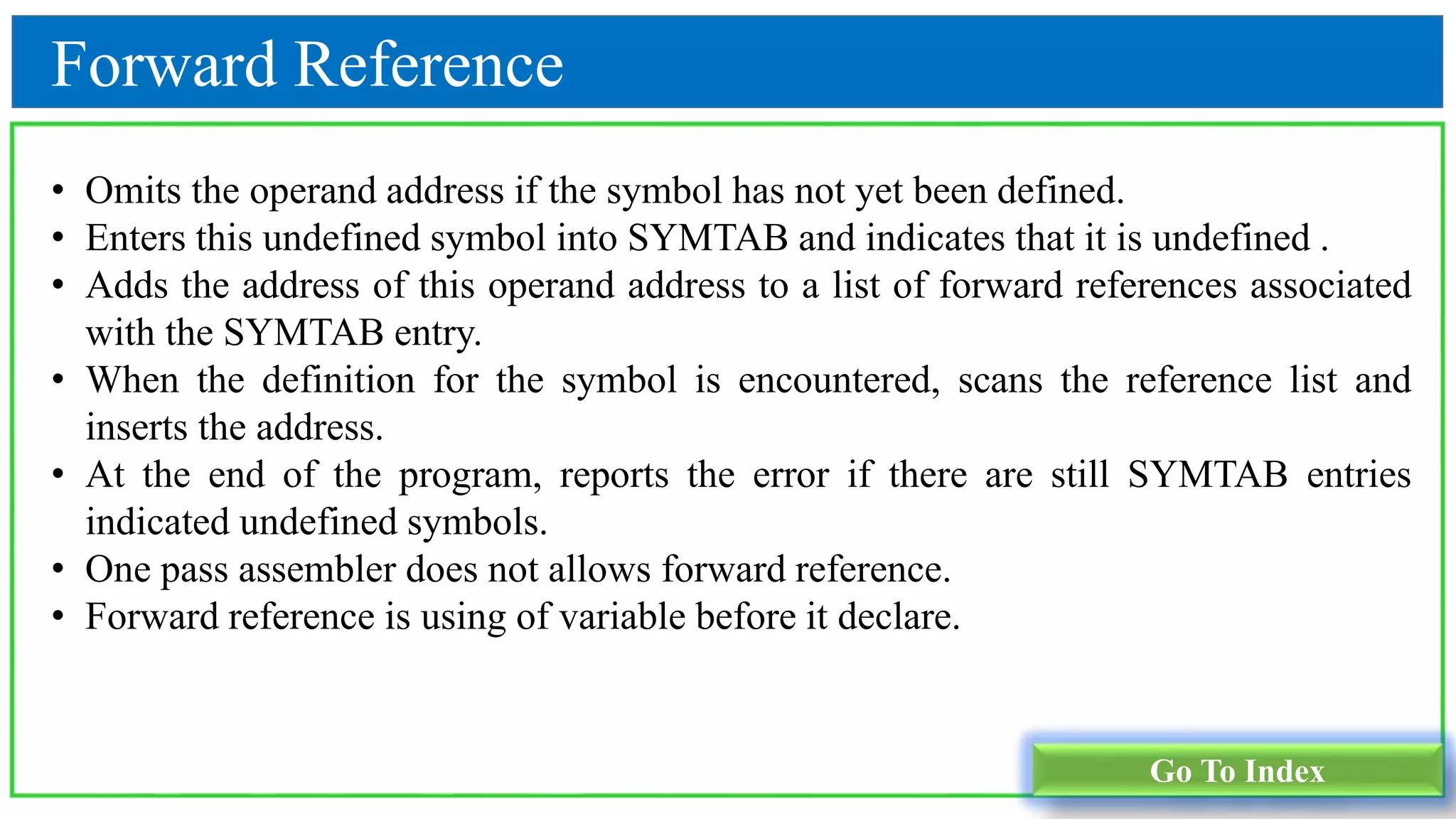
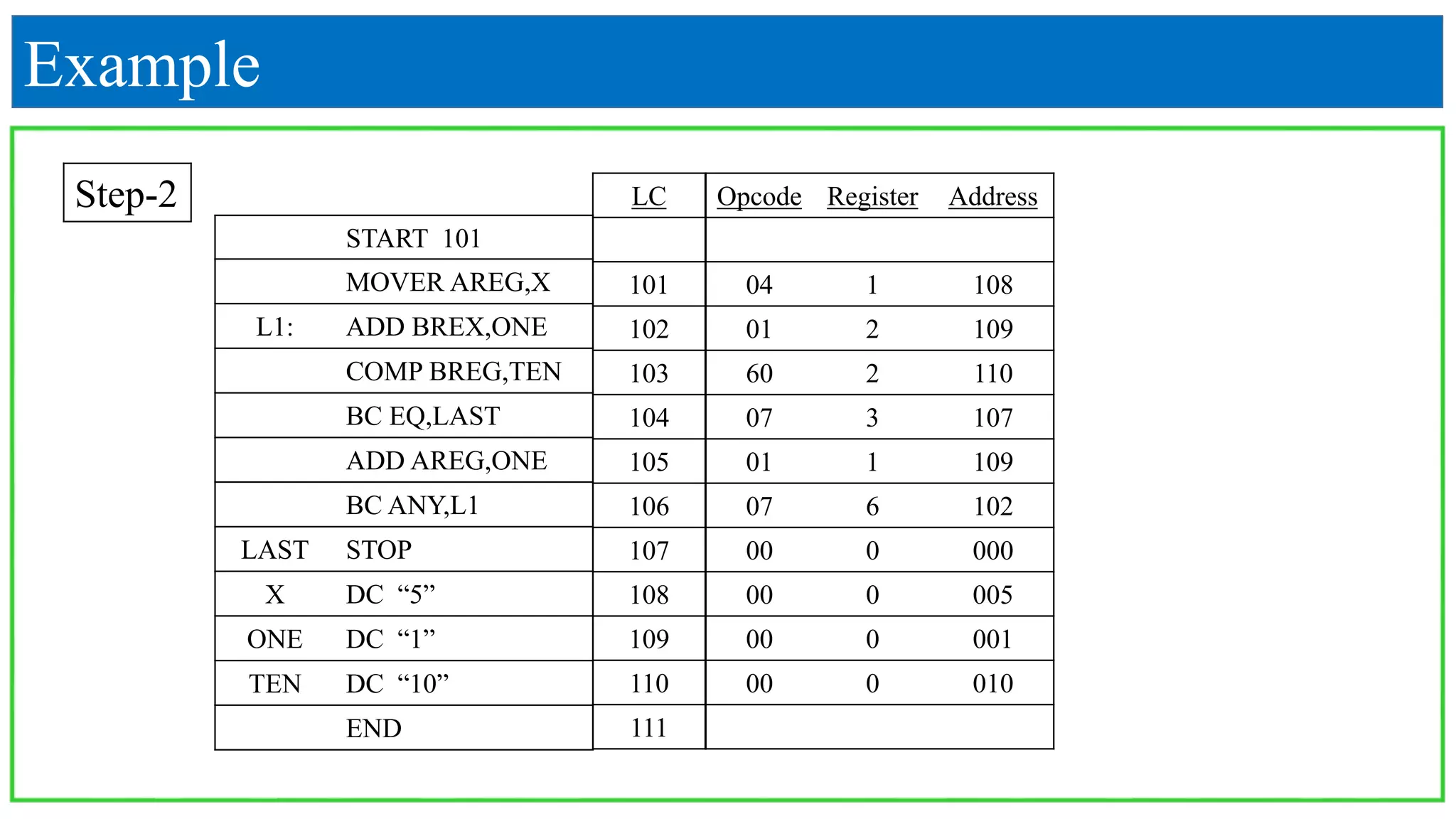
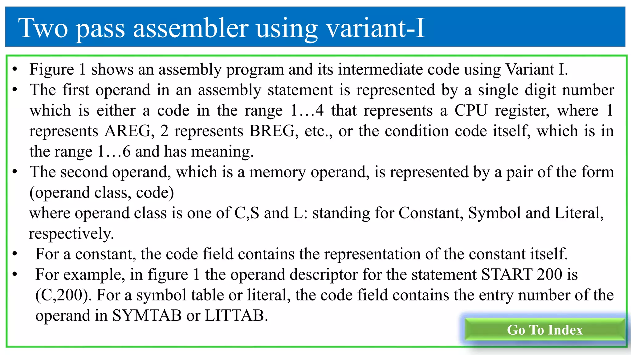
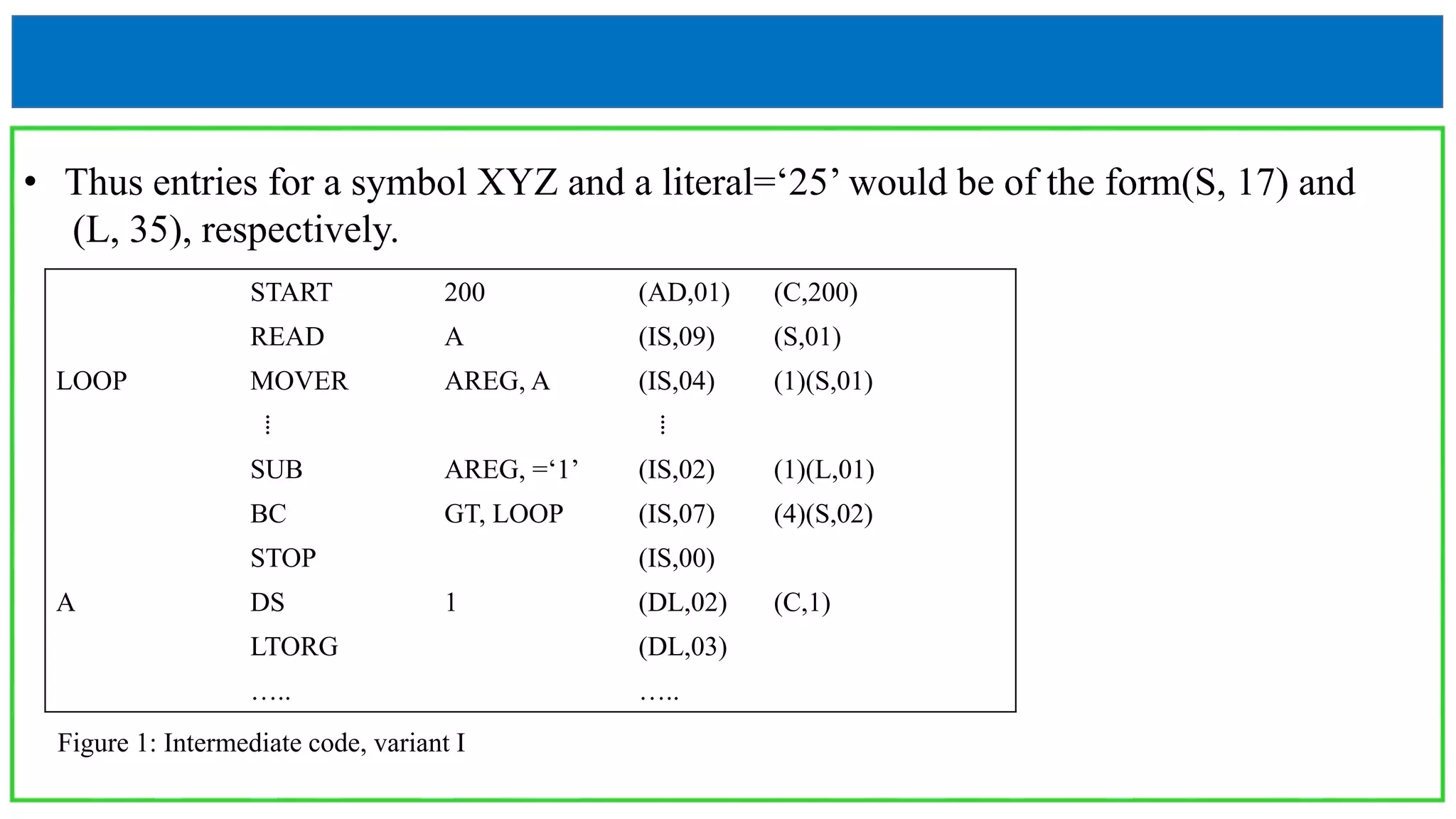
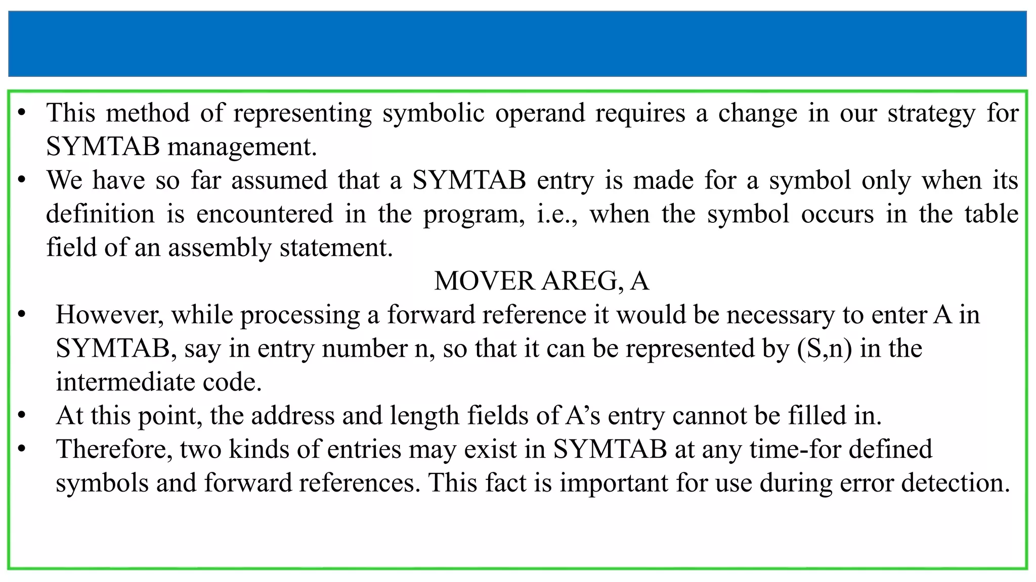
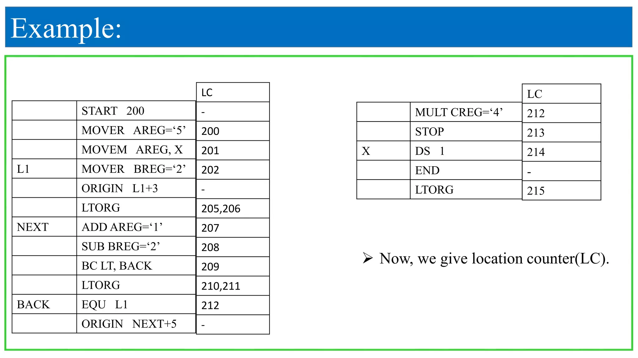
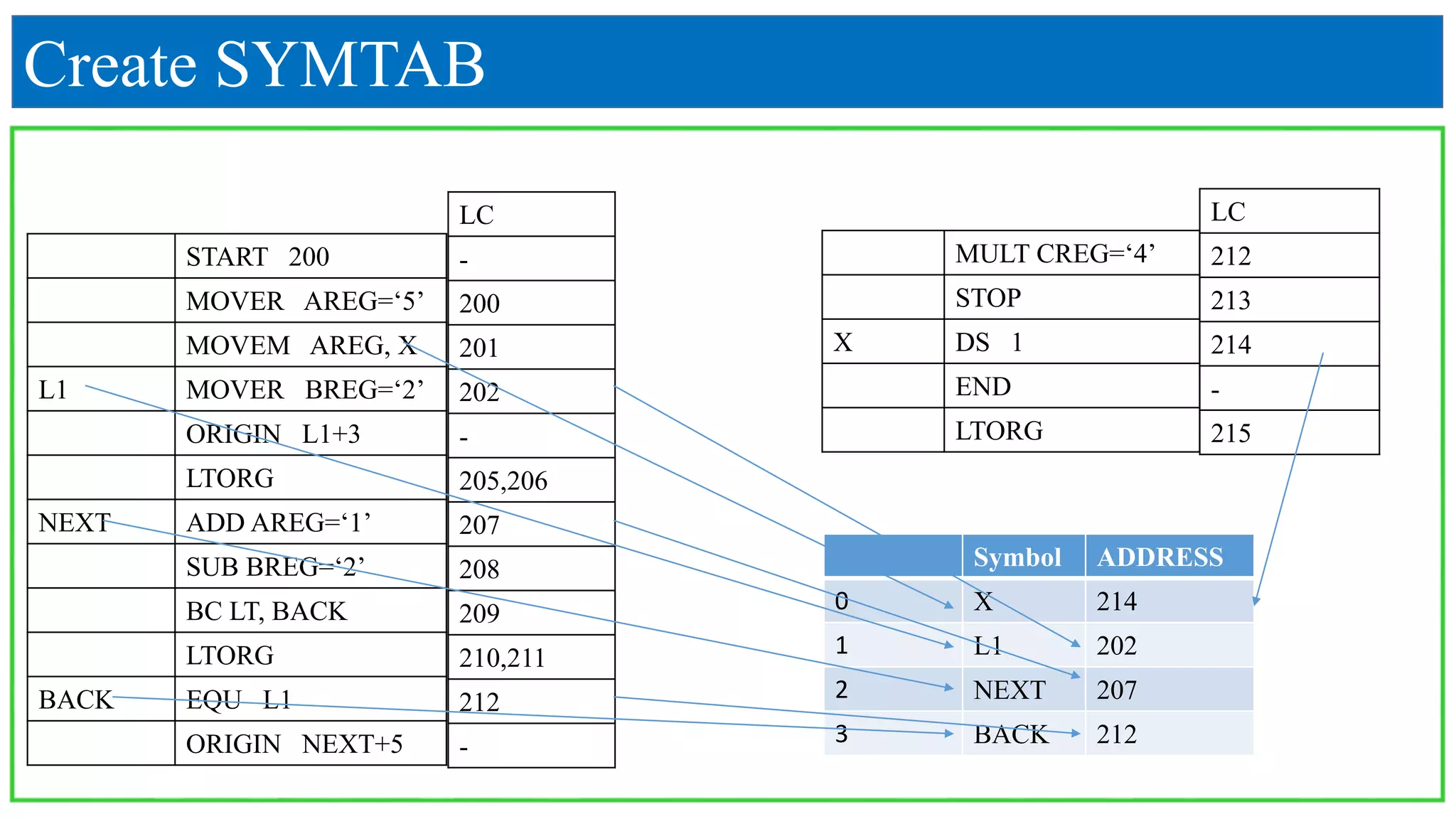
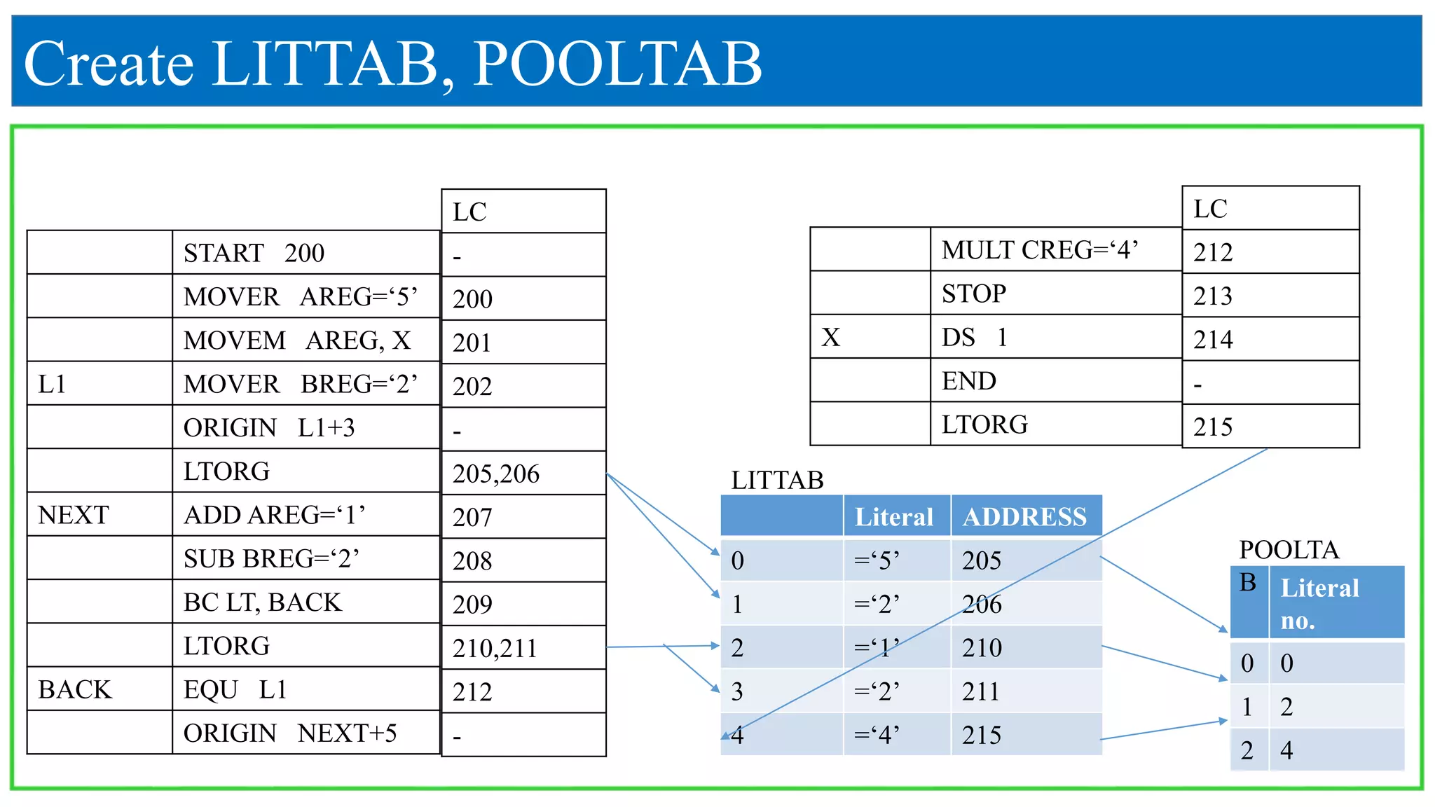
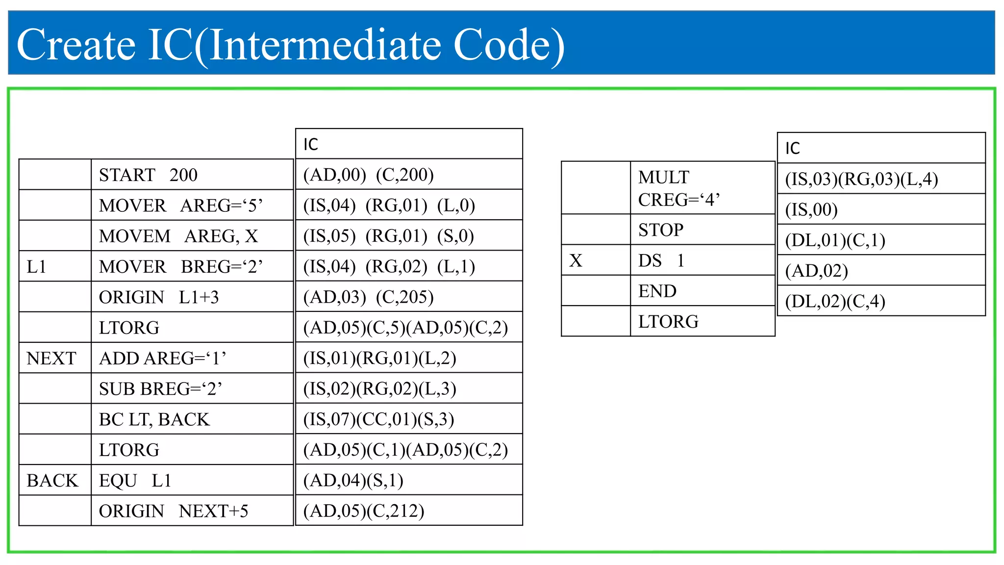
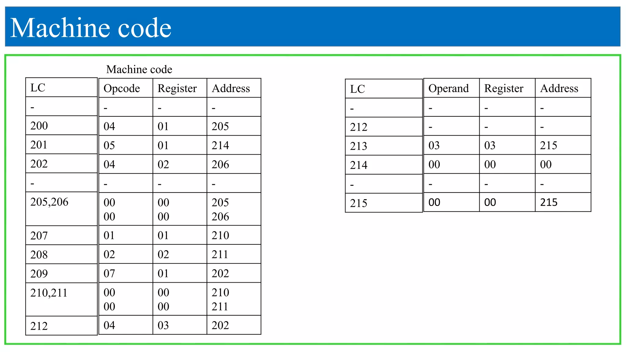
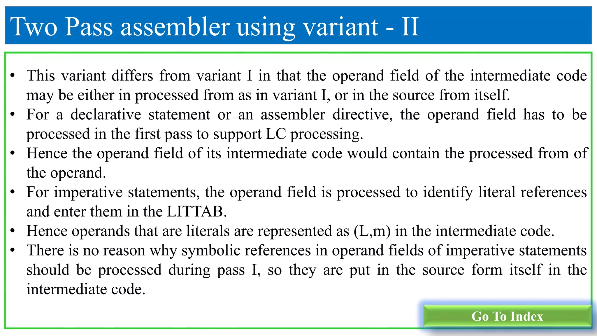
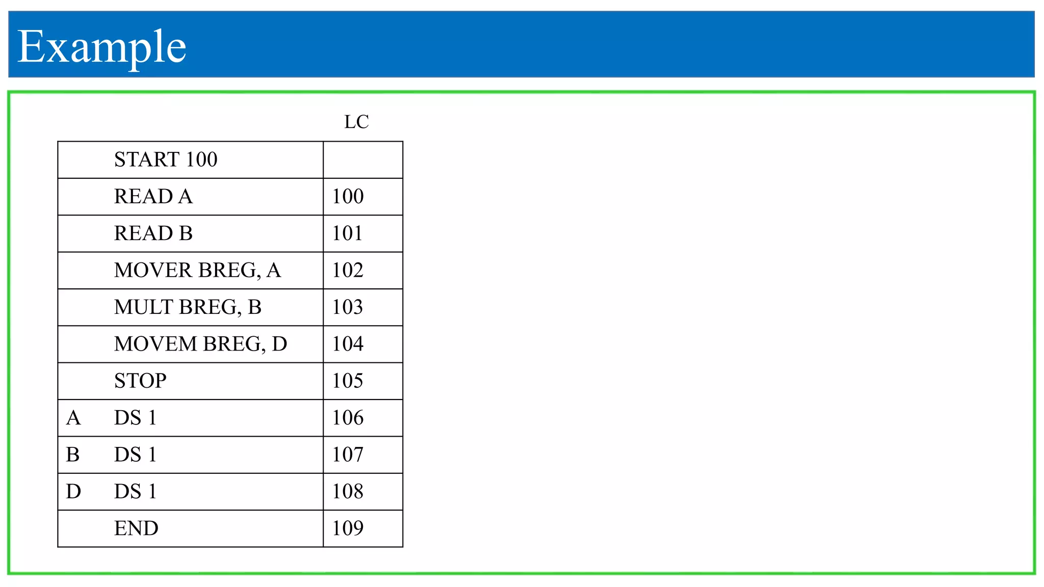
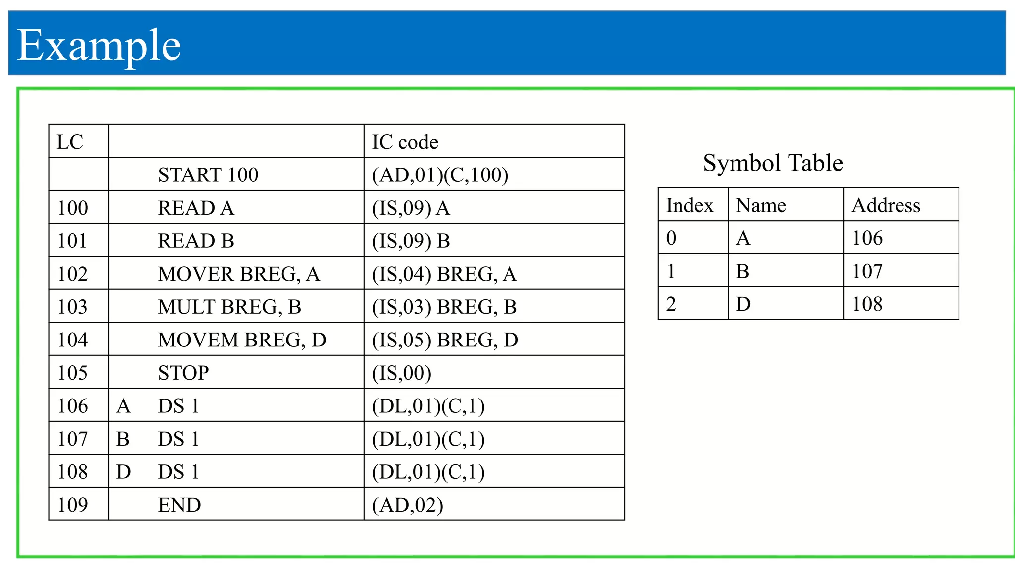
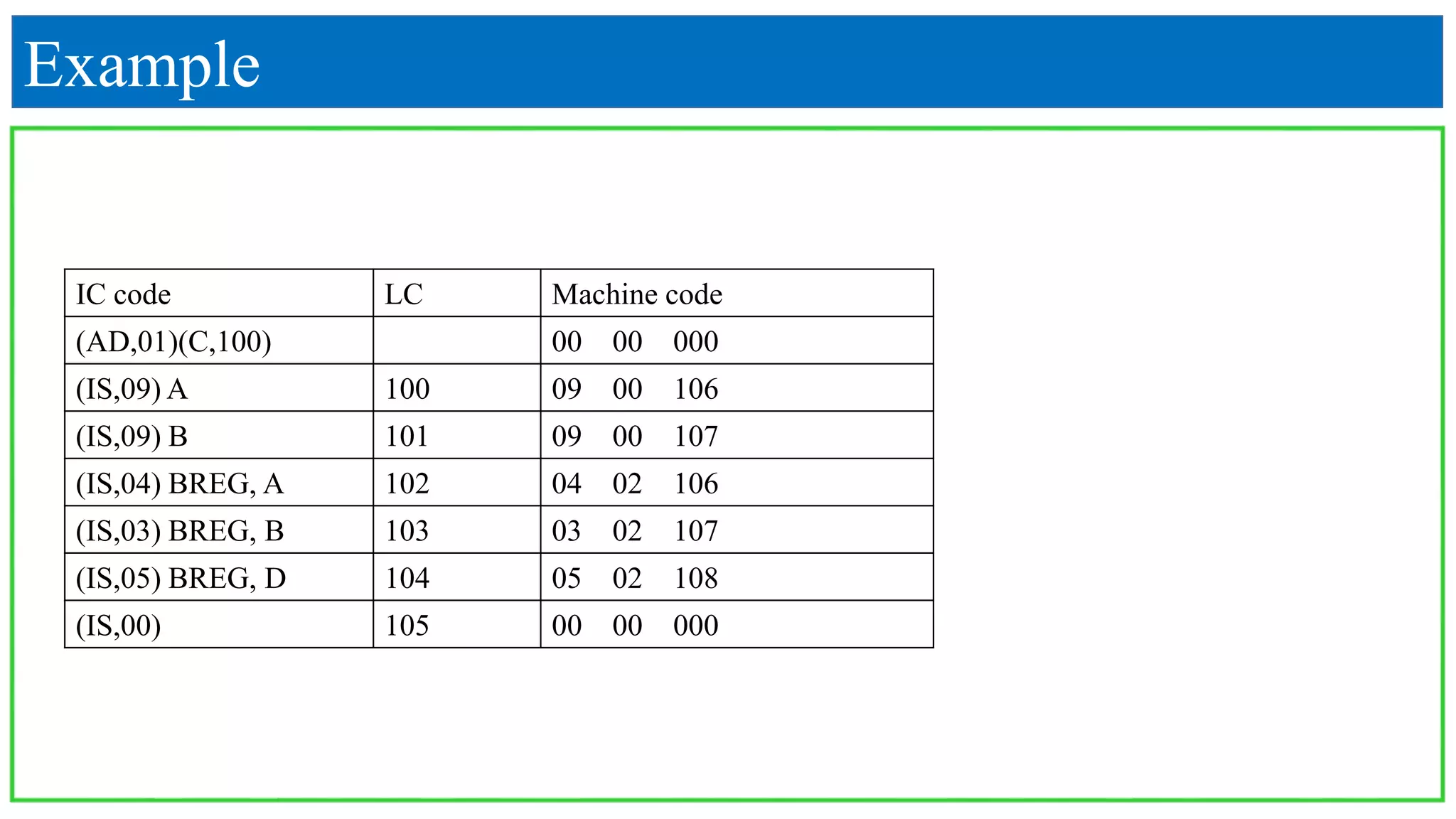
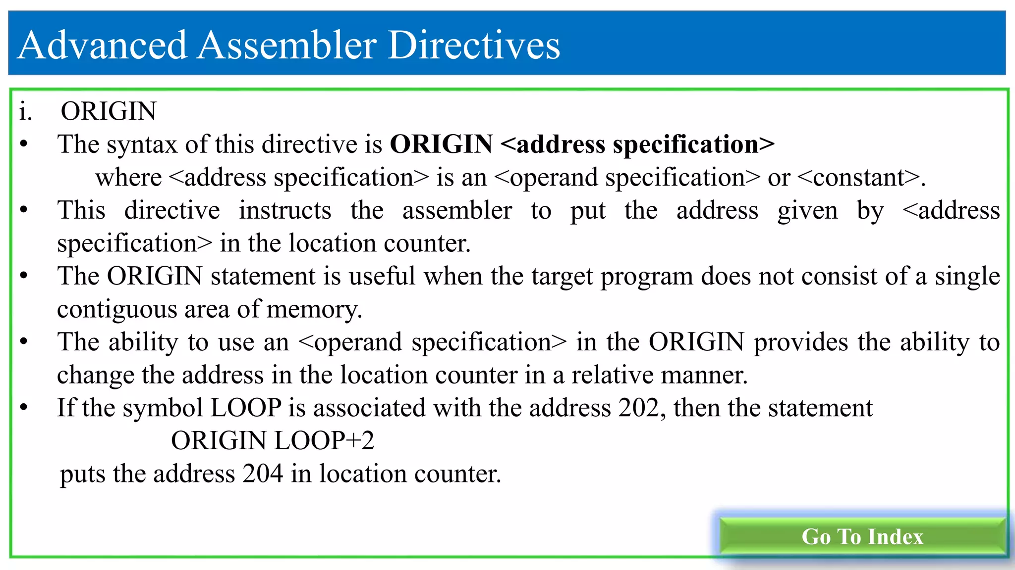
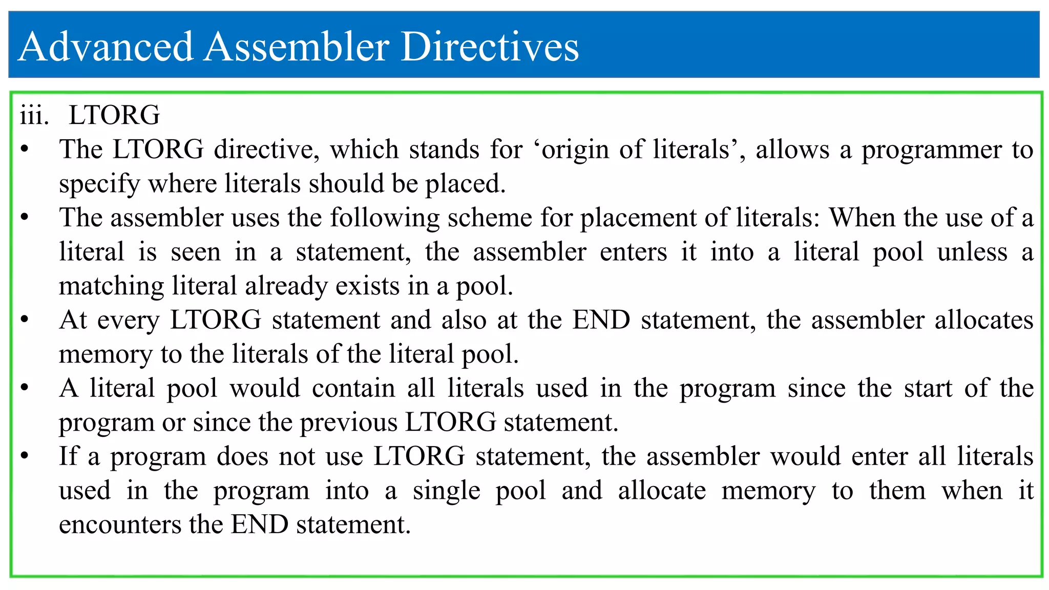
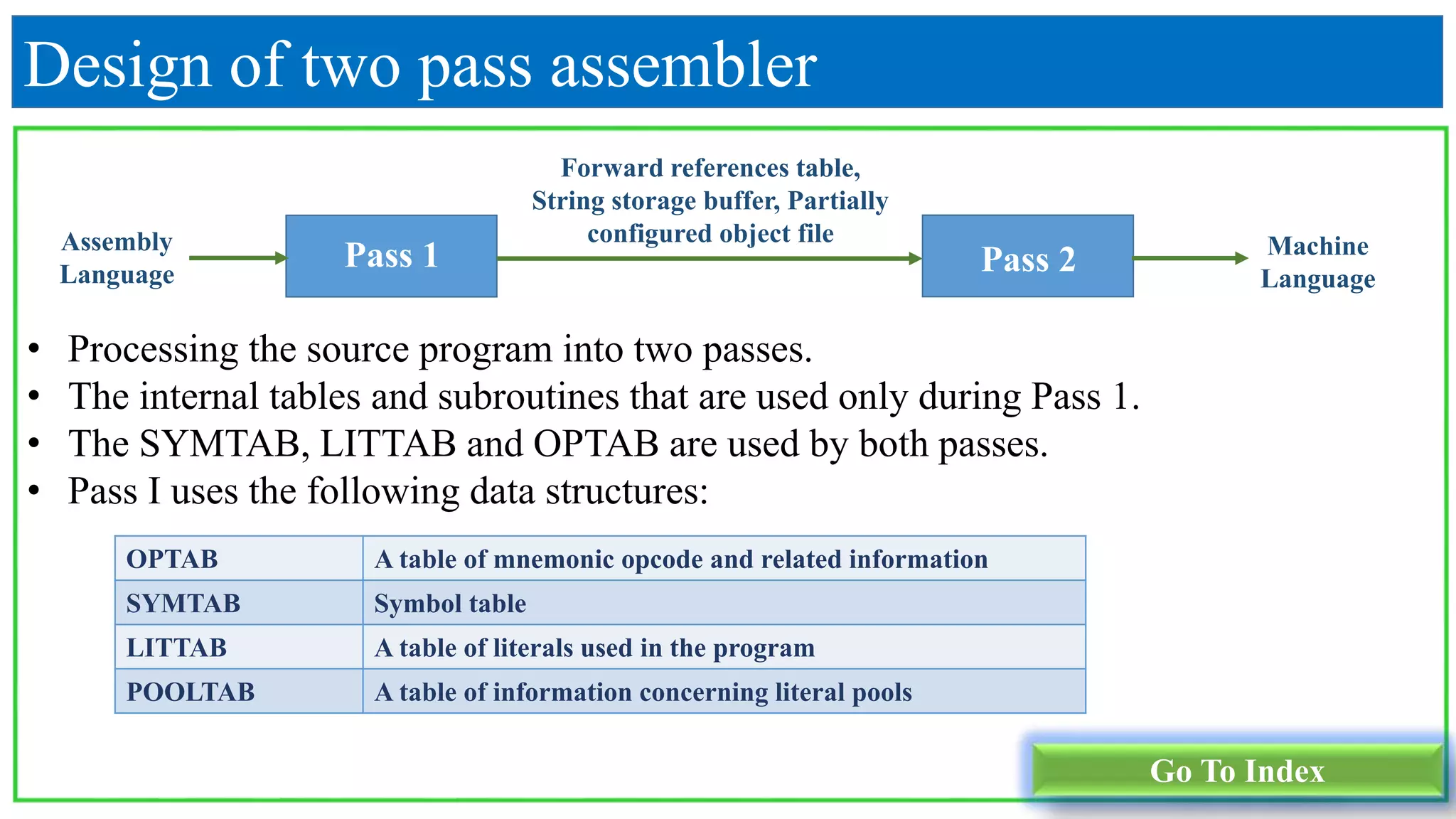
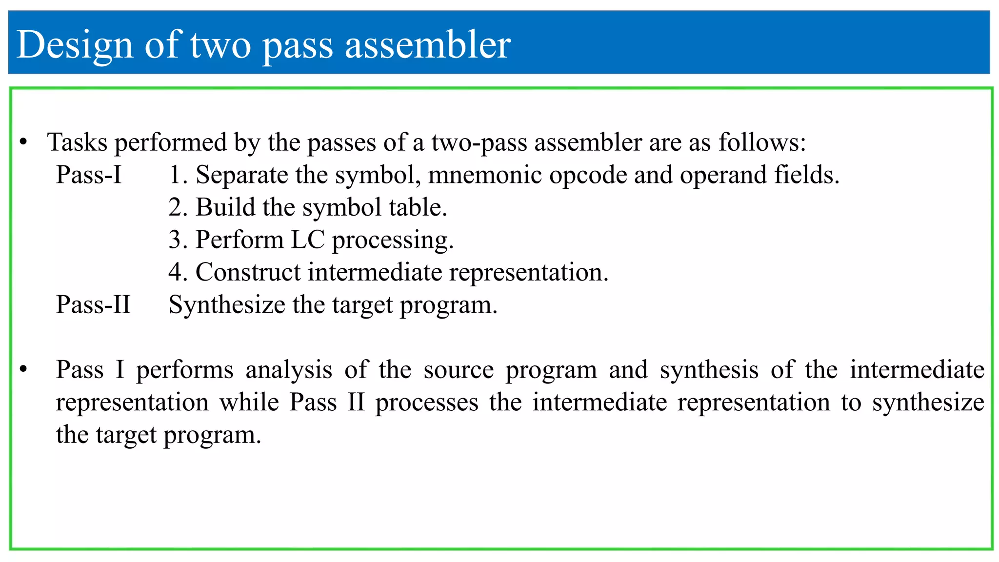
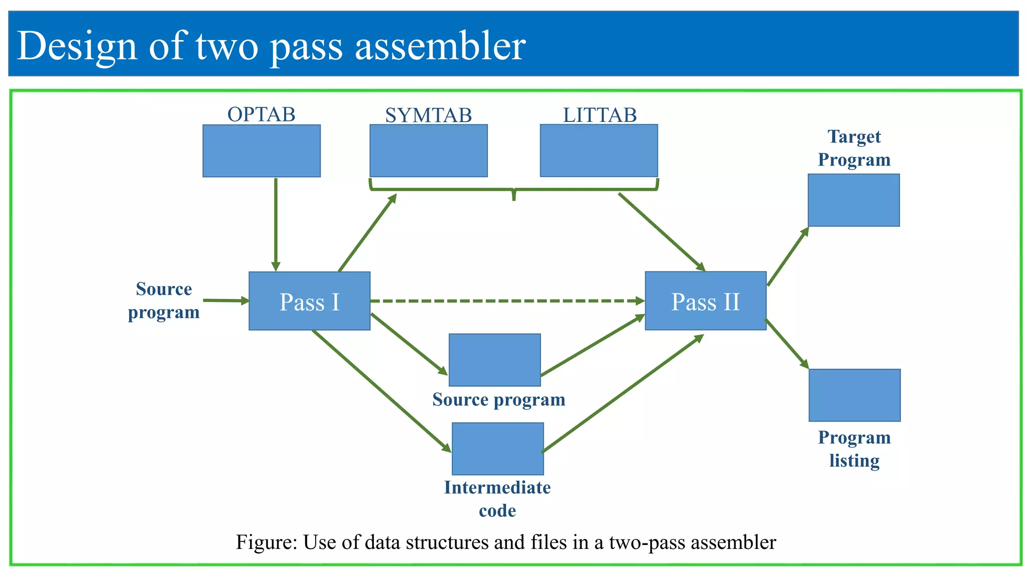
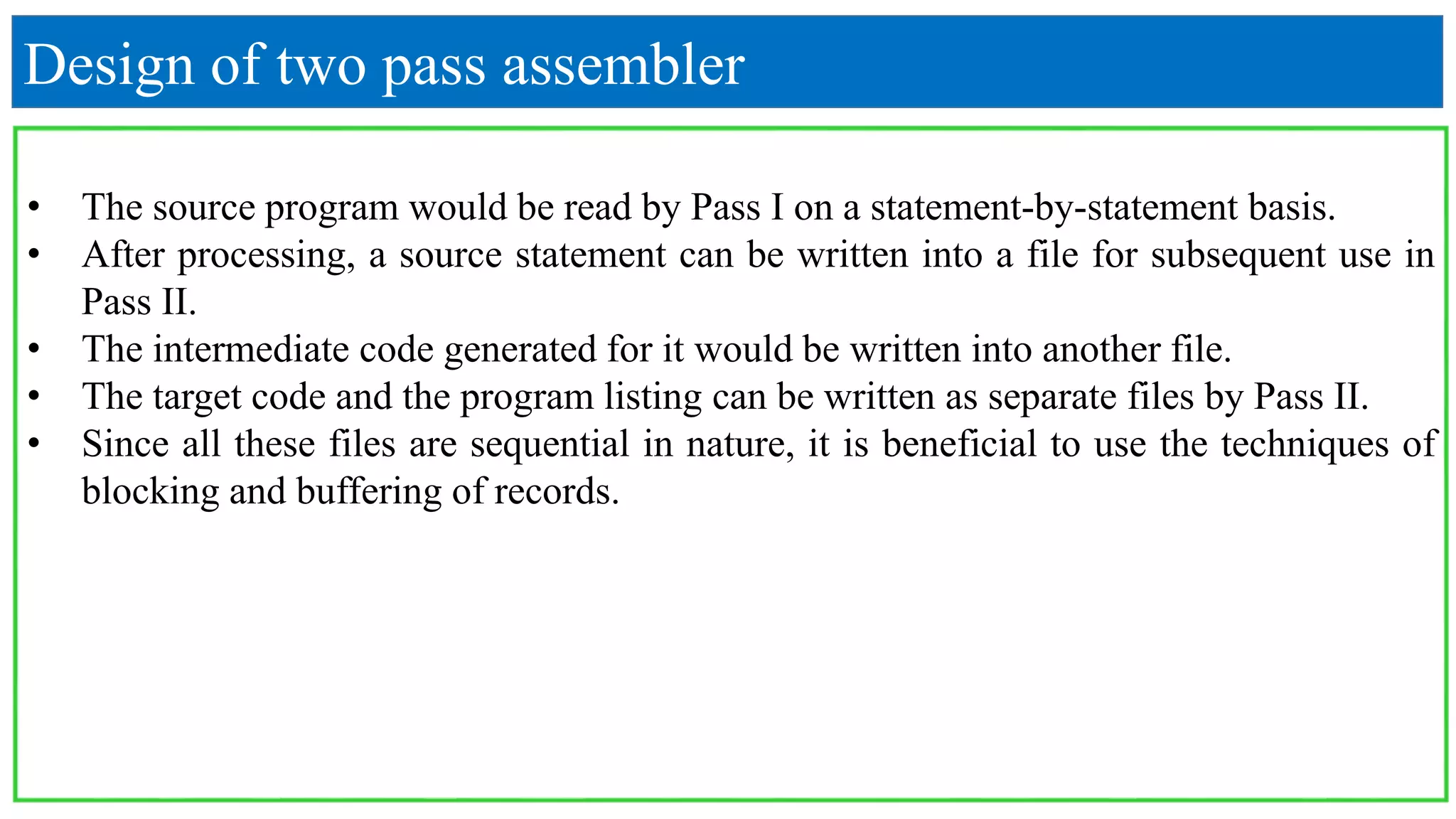
KEMBAR78
Assembler - System Programming | PPTX
SHREE SWAMI ATMANAND SARASWATI INSTITUTE
OF TECHNOLOGY
System Programming (2150708)
PREPARED BY: (Group:2)
Bhumi Aghera(130760107001)
Monika Dudhat(130760107007)
Radhika Talaviya(130760107029)
Rajvi Vaghasiya(130760107031)
GUIDED BY:
Prof. Dharmendra Singh
Prof. Maitry Noticewala
One pass assembler, Two pass assembler,
Advanced Assembler Directives
INDEX
1. One-pass assembler
2. Forward Reference
3. Two-pass assembler using variant-I
4. Two-pass assembler using variant-II
5. Advanced Assembler Directives
6. Design of two pass assembler
One-pass assembler
• Translate assembly language programs to object programs or machine code is
called an Assembler.
• The pass of an assembler is scan of the source program of the source program to
generate a machine code.
• If the operand contains an undefined symbol, use 0 as the address and write the
text record to the object program.
• Forward references are entered into lists as in the load-and-go assembler.
• When the definition of a symbol is encountered, the assembler generates another
Text record with the correct operand address of each entry in the reference list.
• When loaded, the incorrect address 0 will be updated by the latter Text record
containing the symbol definition.
Go To Index
Example:
START 101
READ X
READ Y
MOVER AREG, X
MULT AREG, Y
MOVEM AREG, RESULT
PRINT RESULT
STOP
X DS 1
Y DS 1
RESULT DS 1
END
Here,
X→108
Y→109
RESULT→110
Step:-1
 Now, we give location
counter(LC).
LC
101
102
103
104
105
106
107
108
109
110
110
Example:
Instruction LC Machine
code
READ X 101 09 0 108
READ Y 102 09 0 109
MOVER AREG, X 103 04 1 108
MULT AREG, Y 104 01 1 109
MOVEM AREG, RESULT 105 05 1 110
PRINT RESULT 106 10 0 110
STOP 107 00 0 000
X DS 1 108 --
Y DS 1 109 --
RESULT DS 1 110 --
Step:-2
LC Opcode Register Address
101 09 0 108
102 09 0 109
103 04 1 108
104 01 1 109
105 05 1 110
106 10 0 110
107 00 0 000
Step:-3
Example
Forward Reference
Go To Index
• Omits the operand address if the symbol has not yet been defined.
• Enters this undefined symbol into SYMTAB and indicates that it is undefined .
• Adds the address of this operand address to a list of forward references associated
with the SYMTAB entry.
• When the definition for the symbol is encountered, scans the reference list and
inserts the address.
• At the end of the program, reports the error if there are still SYMTAB entries
indicated undefined symbols.
• One pass assembler does not allows forward reference.
• Forward reference is using of variable before it declare.
x
Example:
START 101
MOVER AREG,X
L1: ADD BREX,ONE
COMP BREG,TEN
BC EQ,LAST
ADD AREG,ONE
BC ANY,L1
LAST STOP
X DC “5”
ONE DC “1”
TEN DC “10”
END
LC
101
102
103
104
105
106
107
108
109
110
111
Opcode Register Address
04 1 ---
01 2 ---
60 2 ---
07 3 ---
01 1 ---
07 6 ---
000 00 ---
Here, 5 forward reference.
 Table for forward reference
Address Forward reference symbol
101 X
102 ONE
103 TEN
104 LAST
105 ONE
Step-1
START 101
MOVER AREG,X
L1: ADD BREX,ONE
COMP BREG,TEN
BC EQ,LAST
ADD AREG,ONE
BC ANY,L1
LAST STOP
X DC “5”
ONE DC “1”
TEN DC “10”
END
LC
101
102
103
104
105
106
107
108
109
110
111
Opcode Register Address
04 1 108
01 2 109
60 2 110
07 3 107
01 1 109
07 6 102
00 0 000
00 0 005
00 0 001
00 0 010
Example
Step-2
Go To Index
• Figure 1 shows an assembly program and its intermediate code using Variant I.
• The first operand in an assembly statement is represented by a single digit number
which is either a code in the range 1…4 that represents a CPU register, where 1
represents AREG, 2 represents BREG, etc., or the condition code itself, which is in
the range 1…6 and has meaning.
• The second operand, which is a memory operand, is represented by a pair of the form
(operand class, code)
where operand class is one of C,S and L: standing for Constant, Symbol and Literal,
respectively.
• For a constant, the code field contains the representation of the constant itself.
• For example, in figure 1 the operand descriptor for the statement START 200 is
(C,200). For a symbol table or literal, the code field contains the entry number of the
operand in SYMTAB or LITTAB.
Two pass assembler using variant-I
• Thus entries for a symbol XYZ and a literal=‘25’ would be of the form(S, 17) and
(L, 35), respectively.
START 200 (AD,01) (C,200)
READ A (IS,09) (S,01)
LOOP MOVER AREG, A (IS,04) (1)(S,01)
⁞ ⁞
SUB AREG, =‘1’ (IS,02) (1)(L,01)
BC GT, LOOP (IS,07) (4)(S,02)
STOP (IS,00)
A DS 1 (DL,02) (C,1)
LTORG (DL,03)
….. …..
Figure 1: Intermediate code, variant I
• This method of representing symbolic operand requires a change in our strategy for
SYMTAB management.
• We have so far assumed that a SYMTAB entry is made for a symbol only when its
definition is encountered in the program, i.e., when the symbol occurs in the table
field of an assembly statement.
MOVER AREG, A
• However, while processing a forward reference it would be necessary to enter A in
SYMTAB, say in entry number n, so that it can be represented by (S,n) in the
intermediate code.
• At this point, the address and length fields of A’s entry cannot be filled in.
• Therefore, two kinds of entries may exist in SYMTAB at any time-for defined
symbols and forward references. This fact is important for use during error detection.
Example:
START 200
MOVER AREG=‘5’
MOVEM AREG, X
L1 MOVER BREG=‘2’
ORIGIN L1+3
LTORG
NEXT ADD AREG=‘1’
SUB BREG=‘2’
BC LT, BACK
LTORG
BACK EQU L1
ORIGIN NEXT+5
MULT CREG=‘4’
STOP
X DS 1
END
LTORG
 Now, we give location counter(LC).
LC
-
200
201
202
-
205,206
207
208
209
210,211
212
-
LC
212
213
214
-
215
Create SYMTAB
START 200
MOVER AREG=‘5’
MOVEM AREG, X
L1 MOVER BREG=‘2’
ORIGIN L1+3
LTORG
NEXT ADD AREG=‘1’
SUB BREG=‘2’
BC LT, BACK
LTORG
BACK EQU L1
ORIGIN NEXT+5
MULT CREG=‘4’
STOP
X DS 1
END
LTORG
LC
-
200
201
202
-
205,206
207
208
209
210,211
212
-
LC
212
213
214
-
215
Symbol ADDRESS
0 X 214
1 L1 202
2 NEXT 207
3 BACK 212
Create LITTAB, POOLTAB
START 200
MOVER AREG=‘5’
MOVEM AREG, X
L1 MOVER BREG=‘2’
ORIGIN L1+3
LTORG
NEXT ADD AREG=‘1’
SUB BREG=‘2’
BC LT, BACK
LTORG
BACK EQU L1
ORIGIN NEXT+5
MULT CREG=‘4’
STOP
X DS 1
END
LTORG
LC
-
200
201
202
-
205,206
207
208
209
210,211
212
-
LC
212
213
214
-
215
Literal ADDRESS
0 =‘5’ 205
1 =‘2’ 206
2 =‘1’ 210
3 =‘2’ 211
4 =‘4’ 215
Literal
no.
0 0
1 2
2 4
LITTAB
POOLTA
B
Create IC(Intermediate Code)
START 200
MOVER AREG=‘5’
MOVEM AREG, X
L1 MOVER BREG=‘2’
ORIGIN L1+3
LTORG
NEXT ADD AREG=‘1’
SUB BREG=‘2’
BC LT, BACK
LTORG
BACK EQU L1
ORIGIN NEXT+5
MULT
CREG=‘4’
STOP
X DS 1
END
LTORG
IC
(AD,00) (C,200)
(IS,04) (RG,01) (L,0)
(IS,05) (RG,01) (S,0)
(IS,04) (RG,02) (L,1)
(AD,03) (C,205)
(AD,05)(C,5)(AD,05)(C,2)
(IS,01)(RG,01)(L,2)
(IS,02)(RG,02)(L,3)
(IS,07)(CC,01)(S,3)
(AD,05)(C,1)(AD,05)(C,2)
(AD,04)(S,1)
(AD,05)(C,212)
IC
(IS,03)(RG,03)(L,4)
(IS,00)
(DL,01)(C,1)
(AD,02)
(DL,02)(C,4)
Machine code
LC
-
200
201
202
-
205,206
207
208
209
210,211
212
LC
-
212
213
214
-
215
Opcode Register Address
- - -
04 01 205
05 01 214
04 02 206
- - -
00
00
00
00
205
206
01 01 210
02 02 211
07 01 202
00
00
00
00
210
211
04 03 202
Machine code
Operand Register Address
- - -
- - -
03 03 215
00 00 00
- - -
00 00 215
Two Pass assembler using variant - II
• This variant differs from variant I in that the operand field of the intermediate code
may be either in processed from as in variant I, or in the source from itself.
• For a declarative statement or an assembler directive, the operand field has to be
processed in the first pass to support LC processing.
• Hence the operand field of its intermediate code would contain the processed from of
the operand.
• For imperative statements, the operand field is processed to identify literal references
and enter them in the LITTAB.
• Hence operands that are literals are represented as (L,m) in the intermediate code.
• There is no reason why symbolic references in operand fields of imperative statements
should be processed during pass I, so they are put in the source form itself in the
intermediate code.
Go To Index
Example
LC
START 100
READ A 100
READ B 101
MOVER BREG, A 102
MULT BREG, B 103
MOVEM BREG, D 104
STOP 105
A DS 1 106
B DS 1 107
D DS 1 108
END 109
Example
LC IC code
START 100 (AD,01)(C,100)
100 READ A (IS,09) A
101 READ B (IS,09) B
102 MOVER BREG, A (IS,04) BREG, A
103 MULT BREG, B (IS,03) BREG, B
104 MOVEM BREG, D (IS,05) BREG, D
105 STOP (IS,00)
106 A DS 1 (DL,01)(C,1)
107 B DS 1 (DL,01)(C,1)
108 D DS 1 (DL,01)(C,1)
109 END (AD,02)
Index Name Address
0 A 106
1 B 107
2 D 108
Symbol Table
Example
IC code LC Machine code
(AD,01)(C,100) 00 00 000
(IS,09) A 100 09 00 106
(IS,09) B 101 09 00 107
(IS,04) BREG, A 102 04 02 106
(IS,03) BREG, B 103 03 02 107
(IS,05) BREG, D 104 05 02 108
(IS,00) 105 00 00 000
Advanced Assembler Directives
i. ORIGIN
• The syntax of this directive is ORIGIN <address specification>
where <address specification> is an <operand specification> or <constant>.
• This directive instructs the assembler to put the address given by <address
specification> in the location counter.
• The ORIGIN statement is useful when the target program does not consist of a single
contiguous area of memory.
• The ability to use an <operand specification> in the ORIGIN provides the ability to
change the address in the location counter in a relative manner.
• If the symbol LOOP is associated with the address 202, then the statement
ORIGIN LOOP+2
puts the address 204 in location counter.
Go To Index
Advanced Assembler Directives
ii. EQU
• The EQU directive has the syntax <symbol> EQU <address specification>.
where <address specification> is either a <constant> or
< symbolic name > −
+
<displacement>.
• The EQU statement simply associates the name <symbol> with the address specified
by <address specification>.
• However, the address in the location counter is not affected.
• If the symbol LOOP is associated with the address 202, then the statement
BACK EQU LOOP
will associate the symbol BACK with the address of LOOP, i.e. 202.
• In the second pass, the statement BC LT, BACK is assembled as ‘+07 1 202’.
Advanced Assembler Directives
iii. LTORG
• The LTORG directive, which stands for ‘origin of literals’, allows a programmer to
specify where literals should be placed.
• The assembler uses the following scheme for placement of literals: When the use of a
literal is seen in a statement, the assembler enters it into a literal pool unless a
matching literal already exists in a pool.
• At every LTORG statement and also at the END statement, the assembler allocates
memory to the literals of the literal pool.
• A literal pool would contain all literals used in the program since the start of the
program or since the previous LTORG statement.
• If a program does not use LTORG statement, the assembler would enter all literals
used in the program into a single pool and allocate memory to them when it
encounters the END statement.
Design of two pass assembler
• Processing the source program into two passes.
• The internal tables and subroutines that are used only during Pass 1.
• The SYMTAB, LITTAB and OPTAB are used by both passes.
• Pass I uses the following data structures:
Pass 1 Pass 2
Assembly
Language
Machine
Language
Forward references table,
String storage buffer, Partially
configured object file
OPTAB A table of mnemonic opcode and related information
SYMTAB Symbol table
LITTAB A table of literals used in the program
POOLTAB A table of information concerning literal pools
Go To Index
Design of two pass assembler
• Tasks performed by the passes of a two-pass assembler are as follows:
Pass-I 1. Separate the symbol, mnemonic opcode and operand fields.
2. Build the symbol table.
3. Perform LC processing.
4. Construct intermediate representation.
Pass-II Synthesize the target program.
• Pass I performs analysis of the source program and synthesis of the intermediate
representation while Pass II processes the intermediate representation to synthesize
the target program.
Pass I Pass II
OPTAB SYMTAB LITTAB
Source
program
Source program
Intermediate
code
Program
listing
Design of two pass assembler
Target
Program
Figure: Use of data structures and files in a two-pass assembler
Design of two pass assembler
• The source program would be read by Pass I on a statement-by-statement basis.
• After processing, a source statement can be written into a file for subsequent use in
Pass II.
• The intermediate code generated for it would be written into another file.
• The target code and the program listing can be written as separate files by Pass II.
• Since all these files are sequential in nature, it is beneficial to use the techniques of
blocking and buffering of records.
Go To Index

Assembler - System Programming

  • 1.
    SHREE SWAMI ATMANANDSARASWATI INSTITUTE OF TECHNOLOGY System Programming (2150708) PREPARED BY: (Group:2) Bhumi Aghera(130760107001) Monika Dudhat(130760107007) Radhika Talaviya(130760107029) Rajvi Vaghasiya(130760107031) GUIDED BY: Prof. Dharmendra Singh Prof. Maitry Noticewala One pass assembler, Two pass assembler, Advanced Assembler Directives
  • 2.
    INDEX 1. One-pass assembler 2.Forward Reference 3. Two-pass assembler using variant-I 4. Two-pass assembler using variant-II 5. Advanced Assembler Directives 6. Design of two pass assembler
  • 3.
    One-pass assembler • Translateassembly language programs to object programs or machine code is called an Assembler. • The pass of an assembler is scan of the source program of the source program to generate a machine code. • If the operand contains an undefined symbol, use 0 as the address and write the text record to the object program. • Forward references are entered into lists as in the load-and-go assembler. • When the definition of a symbol is encountered, the assembler generates another Text record with the correct operand address of each entry in the reference list. • When loaded, the incorrect address 0 will be updated by the latter Text record containing the symbol definition. Go To Index
  • 4.
    Example: START 101 READ X READY MOVER AREG, X MULT AREG, Y MOVEM AREG, RESULT PRINT RESULT STOP X DS 1 Y DS 1 RESULT DS 1 END Here, X→108 Y→109 RESULT→110 Step:-1  Now, we give location counter(LC). LC 101 102 103 104 105 106 107 108 109 110 110
  • 5.
    Example: Instruction LC Machine code READX 101 09 0 108 READ Y 102 09 0 109 MOVER AREG, X 103 04 1 108 MULT AREG, Y 104 01 1 109 MOVEM AREG, RESULT 105 05 1 110 PRINT RESULT 106 10 0 110 STOP 107 00 0 000 X DS 1 108 -- Y DS 1 109 -- RESULT DS 1 110 -- Step:-2
  • 6.
    LC Opcode RegisterAddress 101 09 0 108 102 09 0 109 103 04 1 108 104 01 1 109 105 05 1 110 106 10 0 110 107 00 0 000 Step:-3 Example
  • 7.
    Forward Reference Go ToIndex • Omits the operand address if the symbol has not yet been defined. • Enters this undefined symbol into SYMTAB and indicates that it is undefined . • Adds the address of this operand address to a list of forward references associated with the SYMTAB entry. • When the definition for the symbol is encountered, scans the reference list and inserts the address. • At the end of the program, reports the error if there are still SYMTAB entries indicated undefined symbols. • One pass assembler does not allows forward reference. • Forward reference is using of variable before it declare.
  • 8.
    x Example: START 101 MOVER AREG,X L1:ADD BREX,ONE COMP BREG,TEN BC EQ,LAST ADD AREG,ONE BC ANY,L1 LAST STOP X DC “5” ONE DC “1” TEN DC “10” END LC 101 102 103 104 105 106 107 108 109 110 111 Opcode Register Address 04 1 --- 01 2 --- 60 2 --- 07 3 --- 01 1 --- 07 6 --- 000 00 --- Here, 5 forward reference.  Table for forward reference Address Forward reference symbol 101 X 102 ONE 103 TEN 104 LAST 105 ONE Step-1
  • 9.
    START 101 MOVER AREG,X L1:ADD BREX,ONE COMP BREG,TEN BC EQ,LAST ADD AREG,ONE BC ANY,L1 LAST STOP X DC “5” ONE DC “1” TEN DC “10” END LC 101 102 103 104 105 106 107 108 109 110 111 Opcode Register Address 04 1 108 01 2 109 60 2 110 07 3 107 01 1 109 07 6 102 00 0 000 00 0 005 00 0 001 00 0 010 Example Step-2
  • 10.
    Go To Index •Figure 1 shows an assembly program and its intermediate code using Variant I. • The first operand in an assembly statement is represented by a single digit number which is either a code in the range 1…4 that represents a CPU register, where 1 represents AREG, 2 represents BREG, etc., or the condition code itself, which is in the range 1…6 and has meaning. • The second operand, which is a memory operand, is represented by a pair of the form (operand class, code) where operand class is one of C,S and L: standing for Constant, Symbol and Literal, respectively. • For a constant, the code field contains the representation of the constant itself. • For example, in figure 1 the operand descriptor for the statement START 200 is (C,200). For a symbol table or literal, the code field contains the entry number of the operand in SYMTAB or LITTAB. Two pass assembler using variant-I
  • 11.
    • Thus entriesfor a symbol XYZ and a literal=‘25’ would be of the form(S, 17) and (L, 35), respectively. START 200 (AD,01) (C,200) READ A (IS,09) (S,01) LOOP MOVER AREG, A (IS,04) (1)(S,01) ⁞ ⁞ SUB AREG, =‘1’ (IS,02) (1)(L,01) BC GT, LOOP (IS,07) (4)(S,02) STOP (IS,00) A DS 1 (DL,02) (C,1) LTORG (DL,03) ….. ….. Figure 1: Intermediate code, variant I
  • 12.
    • This methodof representing symbolic operand requires a change in our strategy for SYMTAB management. • We have so far assumed that a SYMTAB entry is made for a symbol only when its definition is encountered in the program, i.e., when the symbol occurs in the table field of an assembly statement. MOVER AREG, A • However, while processing a forward reference it would be necessary to enter A in SYMTAB, say in entry number n, so that it can be represented by (S,n) in the intermediate code. • At this point, the address and length fields of A’s entry cannot be filled in. • Therefore, two kinds of entries may exist in SYMTAB at any time-for defined symbols and forward references. This fact is important for use during error detection.
  • 13.
    Example: START 200 MOVER AREG=‘5’ MOVEMAREG, X L1 MOVER BREG=‘2’ ORIGIN L1+3 LTORG NEXT ADD AREG=‘1’ SUB BREG=‘2’ BC LT, BACK LTORG BACK EQU L1 ORIGIN NEXT+5 MULT CREG=‘4’ STOP X DS 1 END LTORG  Now, we give location counter(LC). LC - 200 201 202 - 205,206 207 208 209 210,211 212 - LC 212 213 214 - 215
  • 14.
    Create SYMTAB START 200 MOVERAREG=‘5’ MOVEM AREG, X L1 MOVER BREG=‘2’ ORIGIN L1+3 LTORG NEXT ADD AREG=‘1’ SUB BREG=‘2’ BC LT, BACK LTORG BACK EQU L1 ORIGIN NEXT+5 MULT CREG=‘4’ STOP X DS 1 END LTORG LC - 200 201 202 - 205,206 207 208 209 210,211 212 - LC 212 213 214 - 215 Symbol ADDRESS 0 X 214 1 L1 202 2 NEXT 207 3 BACK 212
  • 15.
    Create LITTAB, POOLTAB START200 MOVER AREG=‘5’ MOVEM AREG, X L1 MOVER BREG=‘2’ ORIGIN L1+3 LTORG NEXT ADD AREG=‘1’ SUB BREG=‘2’ BC LT, BACK LTORG BACK EQU L1 ORIGIN NEXT+5 MULT CREG=‘4’ STOP X DS 1 END LTORG LC - 200 201 202 - 205,206 207 208 209 210,211 212 - LC 212 213 214 - 215 Literal ADDRESS 0 =‘5’ 205 1 =‘2’ 206 2 =‘1’ 210 3 =‘2’ 211 4 =‘4’ 215 Literal no. 0 0 1 2 2 4 LITTAB POOLTA B
  • 16.
    Create IC(Intermediate Code) START200 MOVER AREG=‘5’ MOVEM AREG, X L1 MOVER BREG=‘2’ ORIGIN L1+3 LTORG NEXT ADD AREG=‘1’ SUB BREG=‘2’ BC LT, BACK LTORG BACK EQU L1 ORIGIN NEXT+5 MULT CREG=‘4’ STOP X DS 1 END LTORG IC (AD,00) (C,200) (IS,04) (RG,01) (L,0) (IS,05) (RG,01) (S,0) (IS,04) (RG,02) (L,1) (AD,03) (C,205) (AD,05)(C,5)(AD,05)(C,2) (IS,01)(RG,01)(L,2) (IS,02)(RG,02)(L,3) (IS,07)(CC,01)(S,3) (AD,05)(C,1)(AD,05)(C,2) (AD,04)(S,1) (AD,05)(C,212) IC (IS,03)(RG,03)(L,4) (IS,00) (DL,01)(C,1) (AD,02) (DL,02)(C,4)
  • 17.
    Machine code LC - 200 201 202 - 205,206 207 208 209 210,211 212 LC - 212 213 214 - 215 Opcode RegisterAddress - - - 04 01 205 05 01 214 04 02 206 - - - 00 00 00 00 205 206 01 01 210 02 02 211 07 01 202 00 00 00 00 210 211 04 03 202 Machine code Operand Register Address - - - - - - 03 03 215 00 00 00 - - - 00 00 215
  • 18.
    Two Pass assemblerusing variant - II • This variant differs from variant I in that the operand field of the intermediate code may be either in processed from as in variant I, or in the source from itself. • For a declarative statement or an assembler directive, the operand field has to be processed in the first pass to support LC processing. • Hence the operand field of its intermediate code would contain the processed from of the operand. • For imperative statements, the operand field is processed to identify literal references and enter them in the LITTAB. • Hence operands that are literals are represented as (L,m) in the intermediate code. • There is no reason why symbolic references in operand fields of imperative statements should be processed during pass I, so they are put in the source form itself in the intermediate code. Go To Index
  • 19.
    Example LC START 100 READ A100 READ B 101 MOVER BREG, A 102 MULT BREG, B 103 MOVEM BREG, D 104 STOP 105 A DS 1 106 B DS 1 107 D DS 1 108 END 109
  • 20.
    Example LC IC code START100 (AD,01)(C,100) 100 READ A (IS,09) A 101 READ B (IS,09) B 102 MOVER BREG, A (IS,04) BREG, A 103 MULT BREG, B (IS,03) BREG, B 104 MOVEM BREG, D (IS,05) BREG, D 105 STOP (IS,00) 106 A DS 1 (DL,01)(C,1) 107 B DS 1 (DL,01)(C,1) 108 D DS 1 (DL,01)(C,1) 109 END (AD,02) Index Name Address 0 A 106 1 B 107 2 D 108 Symbol Table
  • 21.
    Example IC code LCMachine code (AD,01)(C,100) 00 00 000 (IS,09) A 100 09 00 106 (IS,09) B 101 09 00 107 (IS,04) BREG, A 102 04 02 106 (IS,03) BREG, B 103 03 02 107 (IS,05) BREG, D 104 05 02 108 (IS,00) 105 00 00 000
  • 22.
    Advanced Assembler Directives i.ORIGIN • The syntax of this directive is ORIGIN <address specification> where <address specification> is an <operand specification> or <constant>. • This directive instructs the assembler to put the address given by <address specification> in the location counter. • The ORIGIN statement is useful when the target program does not consist of a single contiguous area of memory. • The ability to use an <operand specification> in the ORIGIN provides the ability to change the address in the location counter in a relative manner. • If the symbol LOOP is associated with the address 202, then the statement ORIGIN LOOP+2 puts the address 204 in location counter. Go To Index
  • 23.
    Advanced Assembler Directives ii.EQU • The EQU directive has the syntax <symbol> EQU <address specification>. where <address specification> is either a <constant> or < symbolic name > − + <displacement>. • The EQU statement simply associates the name <symbol> with the address specified by <address specification>. • However, the address in the location counter is not affected. • If the symbol LOOP is associated with the address 202, then the statement BACK EQU LOOP will associate the symbol BACK with the address of LOOP, i.e. 202. • In the second pass, the statement BC LT, BACK is assembled as ‘+07 1 202’.
  • 24.
    Advanced Assembler Directives iii.LTORG • The LTORG directive, which stands for ‘origin of literals’, allows a programmer to specify where literals should be placed. • The assembler uses the following scheme for placement of literals: When the use of a literal is seen in a statement, the assembler enters it into a literal pool unless a matching literal already exists in a pool. • At every LTORG statement and also at the END statement, the assembler allocates memory to the literals of the literal pool. • A literal pool would contain all literals used in the program since the start of the program or since the previous LTORG statement. • If a program does not use LTORG statement, the assembler would enter all literals used in the program into a single pool and allocate memory to them when it encounters the END statement.
  • 25.
    Design of twopass assembler • Processing the source program into two passes. • The internal tables and subroutines that are used only during Pass 1. • The SYMTAB, LITTAB and OPTAB are used by both passes. • Pass I uses the following data structures: Pass 1 Pass 2 Assembly Language Machine Language Forward references table, String storage buffer, Partially configured object file OPTAB A table of mnemonic opcode and related information SYMTAB Symbol table LITTAB A table of literals used in the program POOLTAB A table of information concerning literal pools Go To Index
  • 26.
    Design of twopass assembler • Tasks performed by the passes of a two-pass assembler are as follows: Pass-I 1. Separate the symbol, mnemonic opcode and operand fields. 2. Build the symbol table. 3. Perform LC processing. 4. Construct intermediate representation. Pass-II Synthesize the target program. • Pass I performs analysis of the source program and synthesis of the intermediate representation while Pass II processes the intermediate representation to synthesize the target program.
  • 27.
    Pass I PassII OPTAB SYMTAB LITTAB Source program Source program Intermediate code Program listing Design of two pass assembler Target Program Figure: Use of data structures and files in a two-pass assembler
  • 28.
    Design of twopass assembler • The source program would be read by Pass I on a statement-by-statement basis. • After processing, a source statement can be written into a file for subsequent use in Pass II. • The intermediate code generated for it would be written into another file. • The target code and the program listing can be written as separate files by Pass II. • Since all these files are sequential in nature, it is beneficial to use the techniques of blocking and buffering of records.
  • 29.