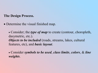
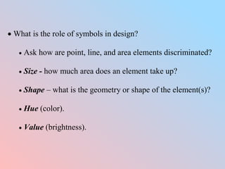
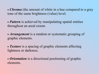
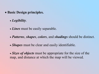
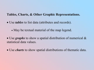
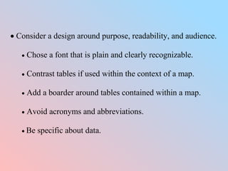
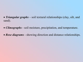
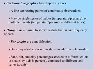
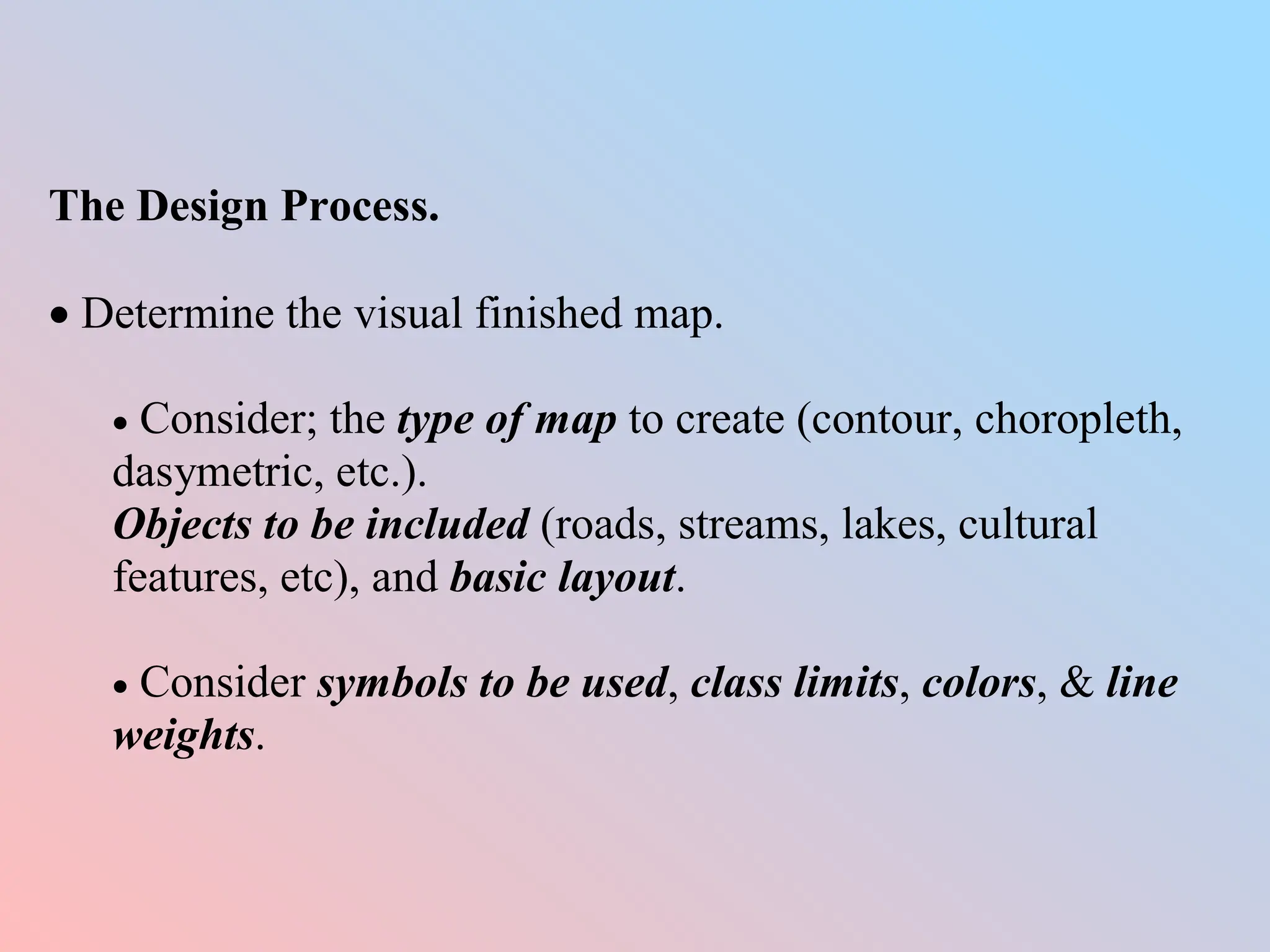
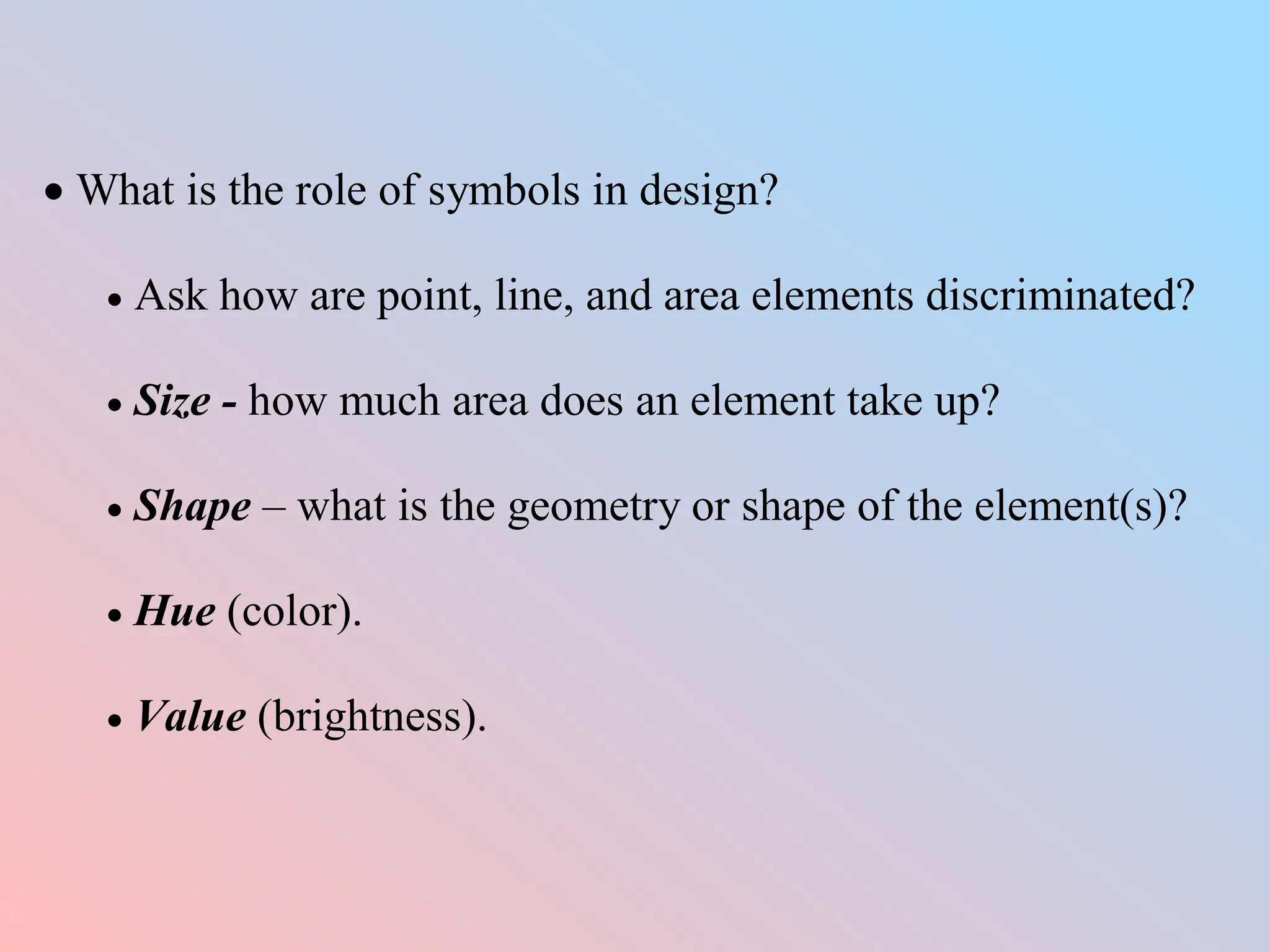
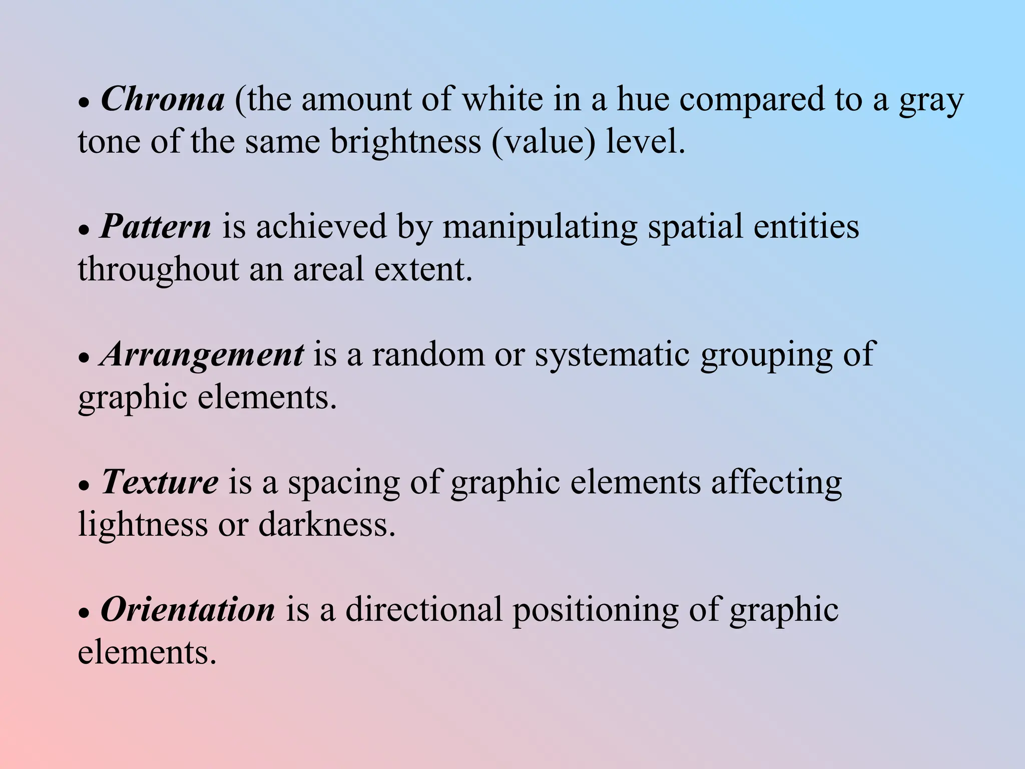
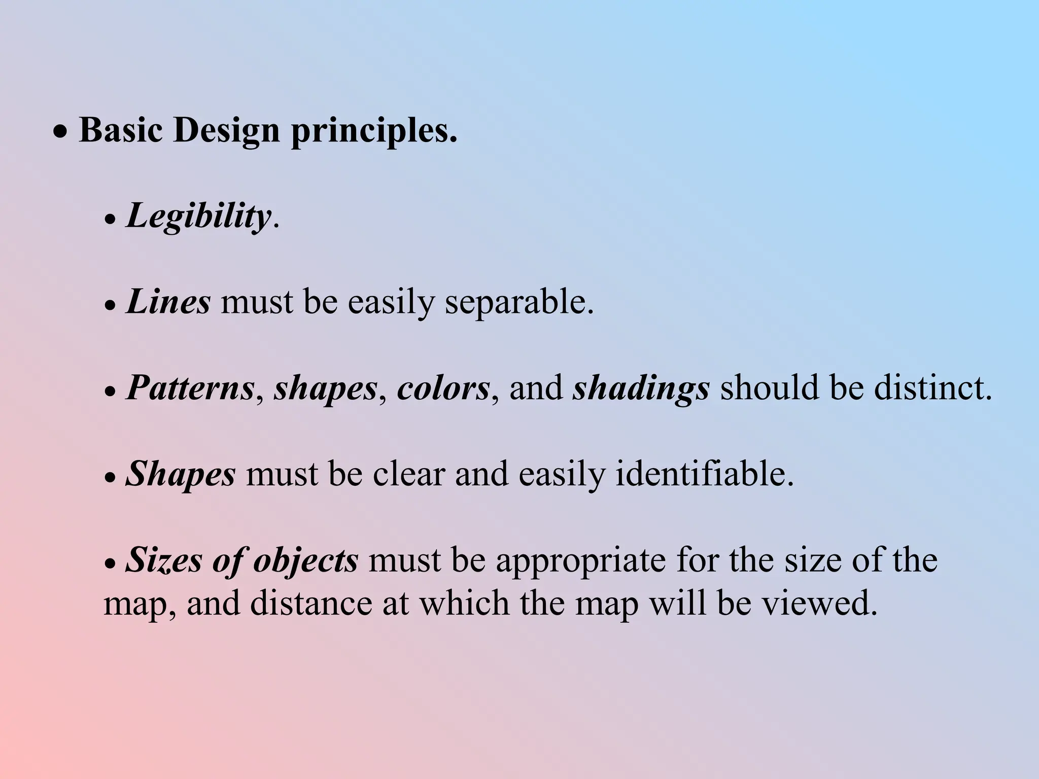
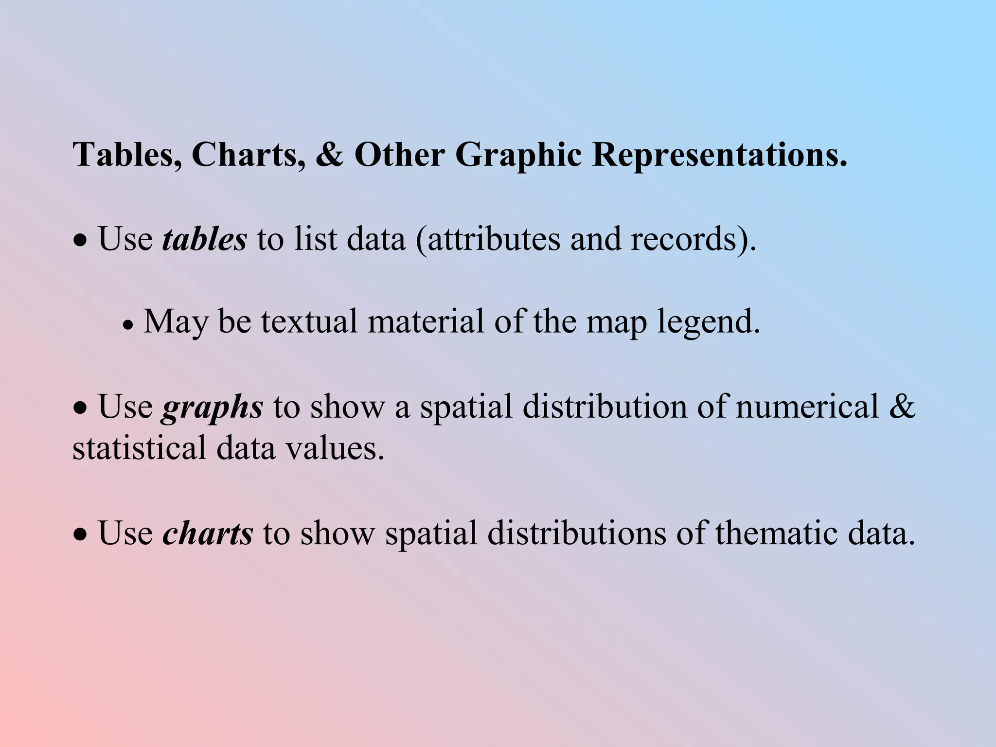
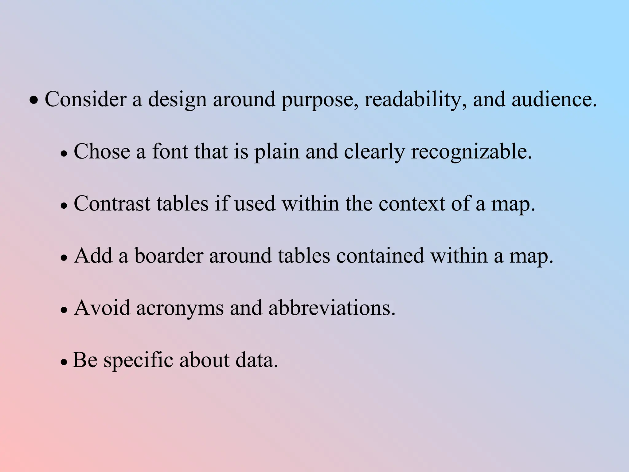
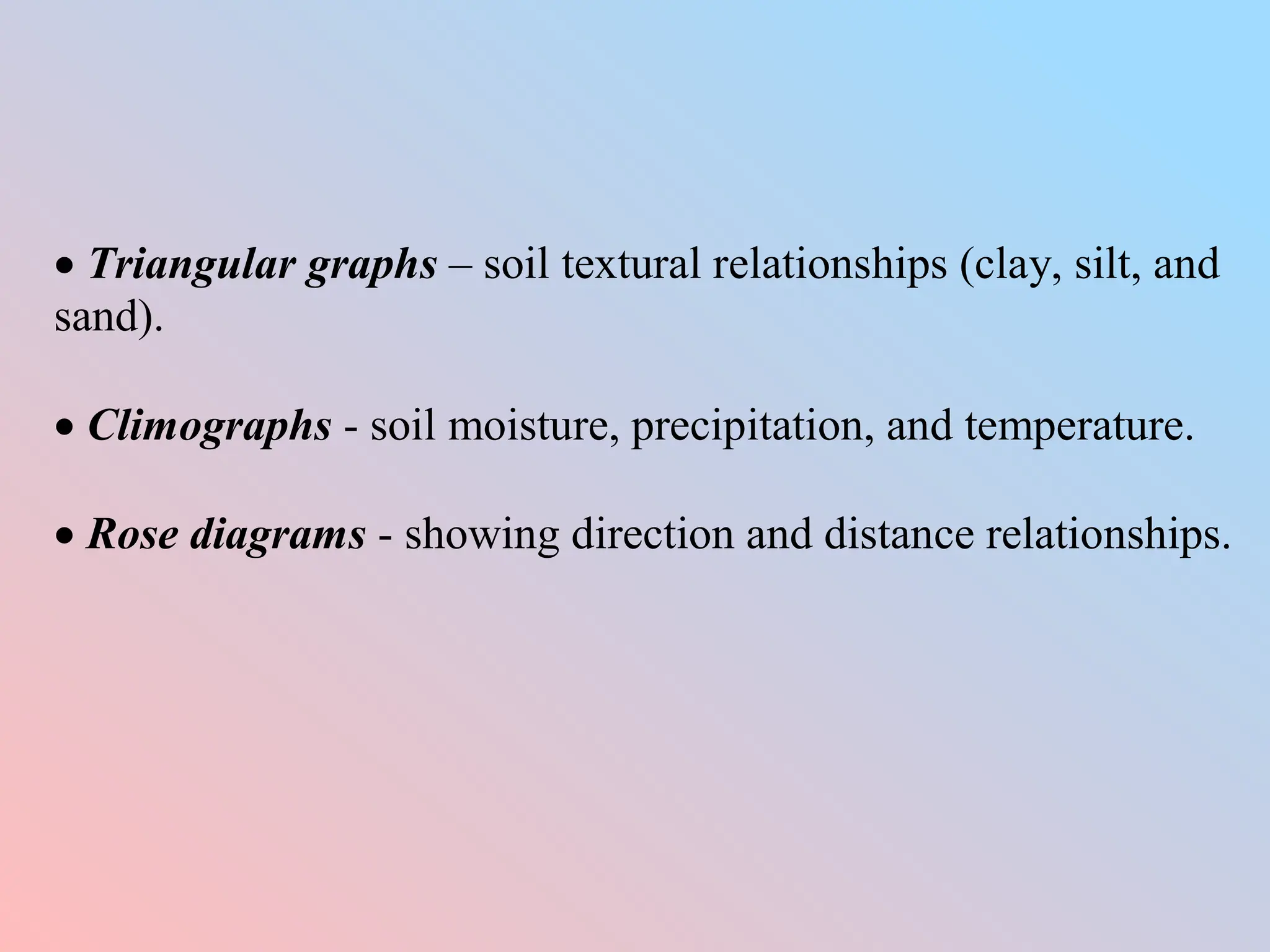
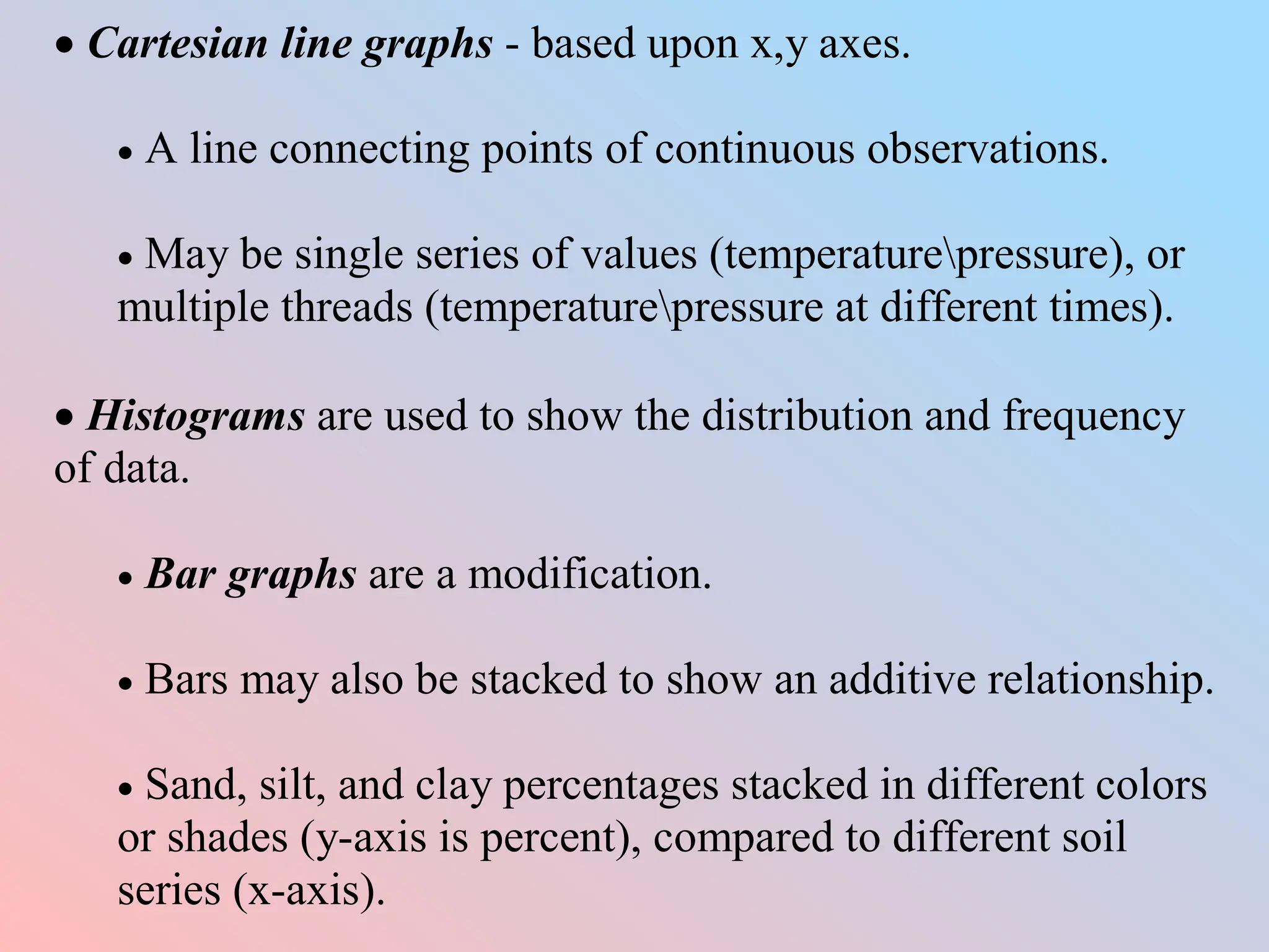
KEMBAR78
CARTOGRAPHIC_OUTPUT.ppt
CARTOGRAPHIC OUTPUT
Display of Analysis
 A GIS is a means for analyzing spatial data. Cartographic
output is the means for communicating this information.
 Permanent output – printed, plotted, or stored on magnetic
tape, laser disk, etc.
 Ephemeral output - text or images that are viewed on a
CRT, overhead screen, etc.
Cartographic Output
 The principal objective of mapping.
 To create a visual image of spatial elements representing
entities interacting within some areal extent.
 General reference maps display a wide variation of spatial
information.
 Topographic map, e.g. contours of elevations, streets,
cultural divisions, waterways, grids, etc.
 Thematic maps display and represent a selected theme
(solution) or subject.
 To select, create, and place symbols and graphic
entities over a spatially defined area.
 A map is designed to be read, analyzed, and
interpreted.
 Objects displayed on a map should be necessary.
Map Conventions.
 Conflicts in map design that requires a number of
standardized decisions.
 The location of naturally-occurring physical features (a
stream or lake) takes precedence over typographical objects
(house symbols) that may not be precisely located.
The Design Process.
 Determine the visual finished map.
 Consider; the type of map to create (contour, choropleth,
dasymetric, etc.).
Objects to be included (roads, streams, lakes, cultural
features, etc), and basic layout.
 Consider symbols to be used, class limits, colors, & line
weights.
 What is the role of symbols in design?
 Ask how are point, line, and area elements discriminated?
 Size - how much area does an element take up?
 Shape – what is the geometry or shape of the element(s)?
 Hue (color).
 Value (brightness).
 Chroma (the amount of white in a hue compared to a gray
tone of the same brightness (value) level.
 Pattern is achieved by manipulating spatial entities
throughout an areal extent.
 Arrangement is a random or systematic grouping of
graphic elements.
 Texture is a spacing of graphic elements affecting
lightness or darkness.
 Orientation is a directional positioning of graphic
elements.
 Basic Design principles.
 Legibility.
 Lines must be easily separable.
 Patterns, shapes, colors, and shadings should be distinct.
 Shapes must be clear and easily identifiable.
 Sizes of objects must be appropriate for the size of the
map, and distance at which the map will be viewed.
 Visual contrast.
 Variances in brightness, colors, and shape of graphic
elements with regard to background.
 Establish a difference between the symbols themselves.
 Establish a difference between the symbols and the
background over which they are drawn.
 Figure-background.
 The ratio of figures to background.
 Balance background area with spatial entities of the map.
 Include shading, value differences, or color to establish
landwater contrast.
 Labels aid in easily identifying significant features.
 Use familiar shapes (state or county boundaries) to isolate
a study area.
 Establish good contour in which the map elements
represent a logical impression of what is on the map.
 Establish a hierarchical structure.
 Organize the graphic elements so that the important features
stand out.
 Stereogrammic method rendering graphic elements to appear
physically higher on the map.
 Changes in line width, color, shading, or size.
 Depth perception is achieved by placing objects on top of
each other.
 Extensional method (hierarchy based upon ordinal data).
 To force the important elements to stand out.
 Varying line symbols for roads, streams, etc.
 Subdivisional method (hierarchy based upon nominal data).
 Creating smaller classes.
 Using varying line widths or color and stippling to
discriminate class features.
Map Design Controls
 What is the purpose for which a map is created?
 Substantive objective, the nature of the data and information
displayed.
 Simplicity.
 Focus.
 Affective objective, or how the data are presented?
 Form of presentation.
 How to convey a message by focusing on a specific
thematic content.
 Reality, how well the limits of each mapped entity represent
itself in the map design?
 Available data.
 Select specific data germane to the analysis (thinning
excessive data).
 Variances in degree of detail, temporal variances, etc.
Operate on the “weakest link” theory.
 Scale variances.
 Smaller scale maps yield less detail per unit area.
 If using varied scaled maps in a GIS, again operate on the
“weakest link” theory.
 Audience.
 Consider the level of sophistication of the map compared to
the background of the intended audience.
 Age and ability to visually see the mapped features.
 Conditions of use - Military/field conditions, on a wall, or in a
published report.
 Technical limits.
 Hardware limits.
 Resolution, minimum mapping unit, color variance, etc.
 Nontraditional Cartographic Output
 Fishnet maps, block diagrams, and wire-frame diagrams.
 Good for visual understanding, but limited in analytical
application.
 May control the angle of view, viewing azimuth, and
viewing distance.
 Animation, coupling multiple scenes over a temporal range,
and spatially registered.
 Atmospheric conditions taken from GOES satellites.
 Fly through over terrain.
 Shaded relief maps.
 Shaded to mimic shadows.
 Good for showing relief changes and topographic
variances.
 Digital orthophotographs.
 Photogrammetrically corrected for relief displacement and
lateral shift of locations due to earth curvature, longitudinal
convergence, etc.
 Cartograms.
Graphic output with the appearance of maps, but distances,
directions, and other spatial arrangements have been modified
to illuminate specific applications.
 Route-line types, e.g. mass transit graphics or road atlases
generalizing networks using straight lines to indicate
distance and travel time between locations.
 Central-point linear types, used to modify output from a
functional (weighted) distance model.
 Distance model by difficulty.
 Frictional surface.
 Area type, in which sizes of each mapped study area are
varied.
 Contiguous, all areas are touching, although e.g. total
discharge of identified springs would result in some
locational entities (springs) being larger than others.
 Noncontiguous (exploded), areas are not touching, e.g.
conterminous U.S., and Alaska or Hawaii.
Noncartographic Output
 Maps may not provide –
 A well-understood output for its audience.
 A map is not the appropriate (desired) output medium.
Interactive Output.
 Using a GIS to determine locations of fires, and routing
scenarios for emergency (medical) routes to hospitals.
 May have both mapped and tabular output, e.g. a routing map
from point a to b, and table assigning distances and times
between ancillary locations (towns).
Tables, Charts, & Other Graphic Representations.
 Use tables to list data (attributes and records).
 May be textual material of the map legend.
 Use graphs to show a spatial distribution of numerical &
statistical data values.
 Use charts to show spatial distributions of thematic data.
 Consider a design around purpose, readability, and audience.
 Chose a font that is plain and clearly recognizable.
 Contrast tables if used within the context of a map.
 Add a boarder around tables contained within a map.
 Avoid acronyms and abbreviations.
 Be specific about data.
 Triangular graphs – soil textural relationships (clay, silt, and
sand).
 Climographs - soil moisture, precipitation, and temperature.
 Rose diagrams - showing direction and distance relationships.
 Cartesian line graphs - based upon x,y axes.
 A line connecting points of continuous observations.
 May be single series of values (temperaturepressure), or
multiple threads (temperaturepressure at different times).
 Histograms are used to show the distribution and frequency
of data.
 Bar graphs are a modification.
 Bars may also be stacked to show an additive relationship.
 Sand, silt, and clay percentages stacked in different colors
or shades (y-axis is percent), compared to different soil
series (x-axis).
Design Considerations.
 Do not use stippled patterns that are radically different
(produces eye strain and unappealing results).
 Use clear, simple symbols.
 Avoid fancy, overly stylish graphic options.
 Keep grid lines to a minimum and draw them lightly.
Technology and GIS Output.
Ephemeral output
 CRT (Cathode Ray Tube) - electron beams directed against
a phosphor-coated screen.
 Glowing results, but must be refreshed a minimum of 72
times per second (refresh rate).
 Noninterlaced CRT’s, every line is refreshed.
 Interlaced CRT’s, every other line is refreshed.
 Changes in beam intensity change gray levels or color.
 Spatial resolution is dependent on dots per inch.
 A 20” diagonal screen with a capability of displaying
1024x768 dots would require an ability to store 786,432
pixels in graphic memory per 172th second just to avoid
screen flicker.
Other Display Devices
 LCD (Liquid Crystal Display.
 LED (Light-Emitting Diode).
Permanent Output
 Ink-jet printers and plotters.
 Electrostatic printers and plotters.

CARTOGRAPHIC_OUTPUT.ppt

  • 1.
    CARTOGRAPHIC OUTPUT Display ofAnalysis  A GIS is a means for analyzing spatial data. Cartographic output is the means for communicating this information.  Permanent output – printed, plotted, or stored on magnetic tape, laser disk, etc.  Ephemeral output - text or images that are viewed on a CRT, overhead screen, etc.
  • 2.
    Cartographic Output  Theprincipal objective of mapping.  To create a visual image of spatial elements representing entities interacting within some areal extent.  General reference maps display a wide variation of spatial information.  Topographic map, e.g. contours of elevations, streets, cultural divisions, waterways, grids, etc.
  • 3.
     Thematic mapsdisplay and represent a selected theme (solution) or subject.  To select, create, and place symbols and graphic entities over a spatially defined area.  A map is designed to be read, analyzed, and interpreted.  Objects displayed on a map should be necessary.
  • 4.
    Map Conventions.  Conflictsin map design that requires a number of standardized decisions.  The location of naturally-occurring physical features (a stream or lake) takes precedence over typographical objects (house symbols) that may not be precisely located.
  • 5.
    The Design Process. Determine the visual finished map.  Consider; the type of map to create (contour, choropleth, dasymetric, etc.). Objects to be included (roads, streams, lakes, cultural features, etc), and basic layout.  Consider symbols to be used, class limits, colors, & line weights.
  • 6.
     What isthe role of symbols in design?  Ask how are point, line, and area elements discriminated?  Size - how much area does an element take up?  Shape – what is the geometry or shape of the element(s)?  Hue (color).  Value (brightness).
  • 7.
     Chroma (theamount of white in a hue compared to a gray tone of the same brightness (value) level.  Pattern is achieved by manipulating spatial entities throughout an areal extent.  Arrangement is a random or systematic grouping of graphic elements.  Texture is a spacing of graphic elements affecting lightness or darkness.  Orientation is a directional positioning of graphic elements.
  • 8.
     Basic Designprinciples.  Legibility.  Lines must be easily separable.  Patterns, shapes, colors, and shadings should be distinct.  Shapes must be clear and easily identifiable.  Sizes of objects must be appropriate for the size of the map, and distance at which the map will be viewed.
  • 9.
     Visual contrast. Variances in brightness, colors, and shape of graphic elements with regard to background.  Establish a difference between the symbols themselves.  Establish a difference between the symbols and the background over which they are drawn.
  • 10.
     Figure-background.  Theratio of figures to background.  Balance background area with spatial entities of the map.  Include shading, value differences, or color to establish landwater contrast.  Labels aid in easily identifying significant features.  Use familiar shapes (state or county boundaries) to isolate a study area.  Establish good contour in which the map elements represent a logical impression of what is on the map.
  • 11.
     Establish ahierarchical structure.  Organize the graphic elements so that the important features stand out.  Stereogrammic method rendering graphic elements to appear physically higher on the map.  Changes in line width, color, shading, or size.  Depth perception is achieved by placing objects on top of each other.
  • 12.
     Extensional method(hierarchy based upon ordinal data).  To force the important elements to stand out.  Varying line symbols for roads, streams, etc.  Subdivisional method (hierarchy based upon nominal data).  Creating smaller classes.  Using varying line widths or color and stippling to discriminate class features.
  • 13.
    Map Design Controls What is the purpose for which a map is created?  Substantive objective, the nature of the data and information displayed.  Simplicity.  Focus.  Affective objective, or how the data are presented?  Form of presentation.  How to convey a message by focusing on a specific thematic content.
  • 14.
     Reality, howwell the limits of each mapped entity represent itself in the map design?  Available data.  Select specific data germane to the analysis (thinning excessive data).  Variances in degree of detail, temporal variances, etc. Operate on the “weakest link” theory.  Scale variances.  Smaller scale maps yield less detail per unit area.  If using varied scaled maps in a GIS, again operate on the “weakest link” theory.
  • 15.
     Audience.  Considerthe level of sophistication of the map compared to the background of the intended audience.  Age and ability to visually see the mapped features.  Conditions of use - Military/field conditions, on a wall, or in a published report.  Technical limits.  Hardware limits.  Resolution, minimum mapping unit, color variance, etc.
  • 16.
     Nontraditional CartographicOutput  Fishnet maps, block diagrams, and wire-frame diagrams.  Good for visual understanding, but limited in analytical application.  May control the angle of view, viewing azimuth, and viewing distance.  Animation, coupling multiple scenes over a temporal range, and spatially registered.  Atmospheric conditions taken from GOES satellites.  Fly through over terrain.
  • 17.
     Shaded reliefmaps.  Shaded to mimic shadows.  Good for showing relief changes and topographic variances.  Digital orthophotographs.  Photogrammetrically corrected for relief displacement and lateral shift of locations due to earth curvature, longitudinal convergence, etc.
  • 18.
     Cartograms. Graphic outputwith the appearance of maps, but distances, directions, and other spatial arrangements have been modified to illuminate specific applications.  Route-line types, e.g. mass transit graphics or road atlases generalizing networks using straight lines to indicate distance and travel time between locations.  Central-point linear types, used to modify output from a functional (weighted) distance model.  Distance model by difficulty.  Frictional surface.
  • 19.
     Area type,in which sizes of each mapped study area are varied.  Contiguous, all areas are touching, although e.g. total discharge of identified springs would result in some locational entities (springs) being larger than others.  Noncontiguous (exploded), areas are not touching, e.g. conterminous U.S., and Alaska or Hawaii.
  • 20.
    Noncartographic Output  Mapsmay not provide –  A well-understood output for its audience.  A map is not the appropriate (desired) output medium.
  • 21.
    Interactive Output.  Usinga GIS to determine locations of fires, and routing scenarios for emergency (medical) routes to hospitals.  May have both mapped and tabular output, e.g. a routing map from point a to b, and table assigning distances and times between ancillary locations (towns).
  • 22.
    Tables, Charts, &Other Graphic Representations.  Use tables to list data (attributes and records).  May be textual material of the map legend.  Use graphs to show a spatial distribution of numerical & statistical data values.  Use charts to show spatial distributions of thematic data.
  • 23.
     Consider adesign around purpose, readability, and audience.  Chose a font that is plain and clearly recognizable.  Contrast tables if used within the context of a map.  Add a boarder around tables contained within a map.  Avoid acronyms and abbreviations.  Be specific about data.
  • 24.
     Triangular graphs– soil textural relationships (clay, silt, and sand).  Climographs - soil moisture, precipitation, and temperature.  Rose diagrams - showing direction and distance relationships.
  • 25.
     Cartesian linegraphs - based upon x,y axes.  A line connecting points of continuous observations.  May be single series of values (temperaturepressure), or multiple threads (temperaturepressure at different times).  Histograms are used to show the distribution and frequency of data.  Bar graphs are a modification.  Bars may also be stacked to show an additive relationship.  Sand, silt, and clay percentages stacked in different colors or shades (y-axis is percent), compared to different soil series (x-axis).
  • 26.
    Design Considerations.  Donot use stippled patterns that are radically different (produces eye strain and unappealing results).  Use clear, simple symbols.  Avoid fancy, overly stylish graphic options.  Keep grid lines to a minimum and draw them lightly.
  • 27.
    Technology and GISOutput. Ephemeral output  CRT (Cathode Ray Tube) - electron beams directed against a phosphor-coated screen.
  • 28.
     Glowing results,but must be refreshed a minimum of 72 times per second (refresh rate).  Noninterlaced CRT’s, every line is refreshed.  Interlaced CRT’s, every other line is refreshed.  Changes in beam intensity change gray levels or color.  Spatial resolution is dependent on dots per inch.  A 20” diagonal screen with a capability of displaying 1024x768 dots would require an ability to store 786,432 pixels in graphic memory per 172th second just to avoid screen flicker.
  • 29.
    Other Display Devices LCD (Liquid Crystal Display.  LED (Light-Emitting Diode). Permanent Output  Ink-jet printers and plotters.  Electrostatic printers and plotters.