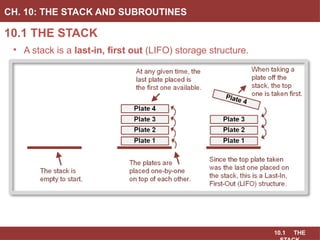
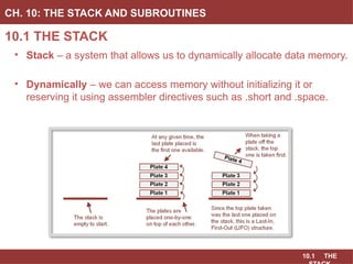
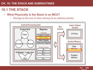
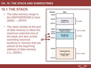
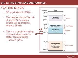
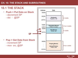
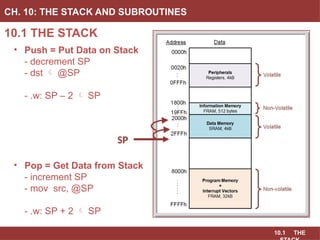
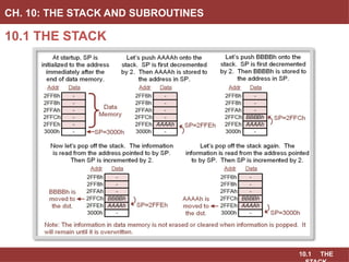
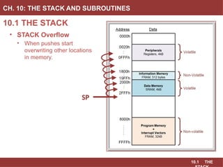
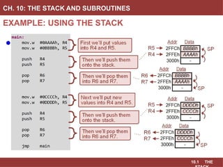
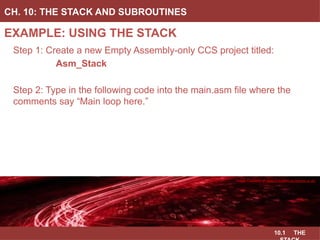
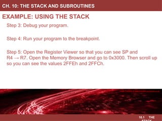
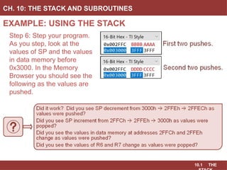
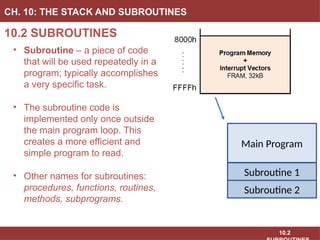
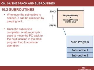
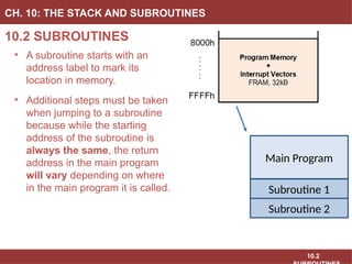
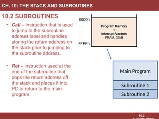
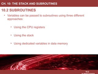
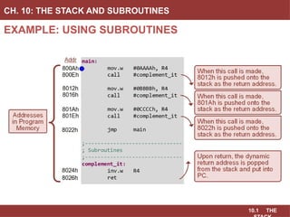
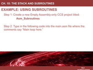
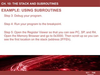
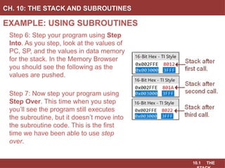
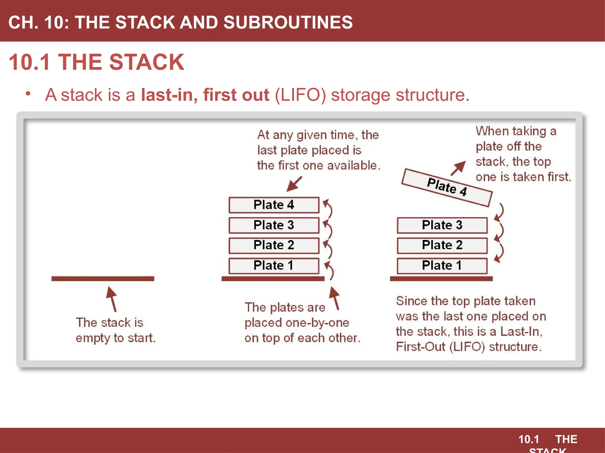
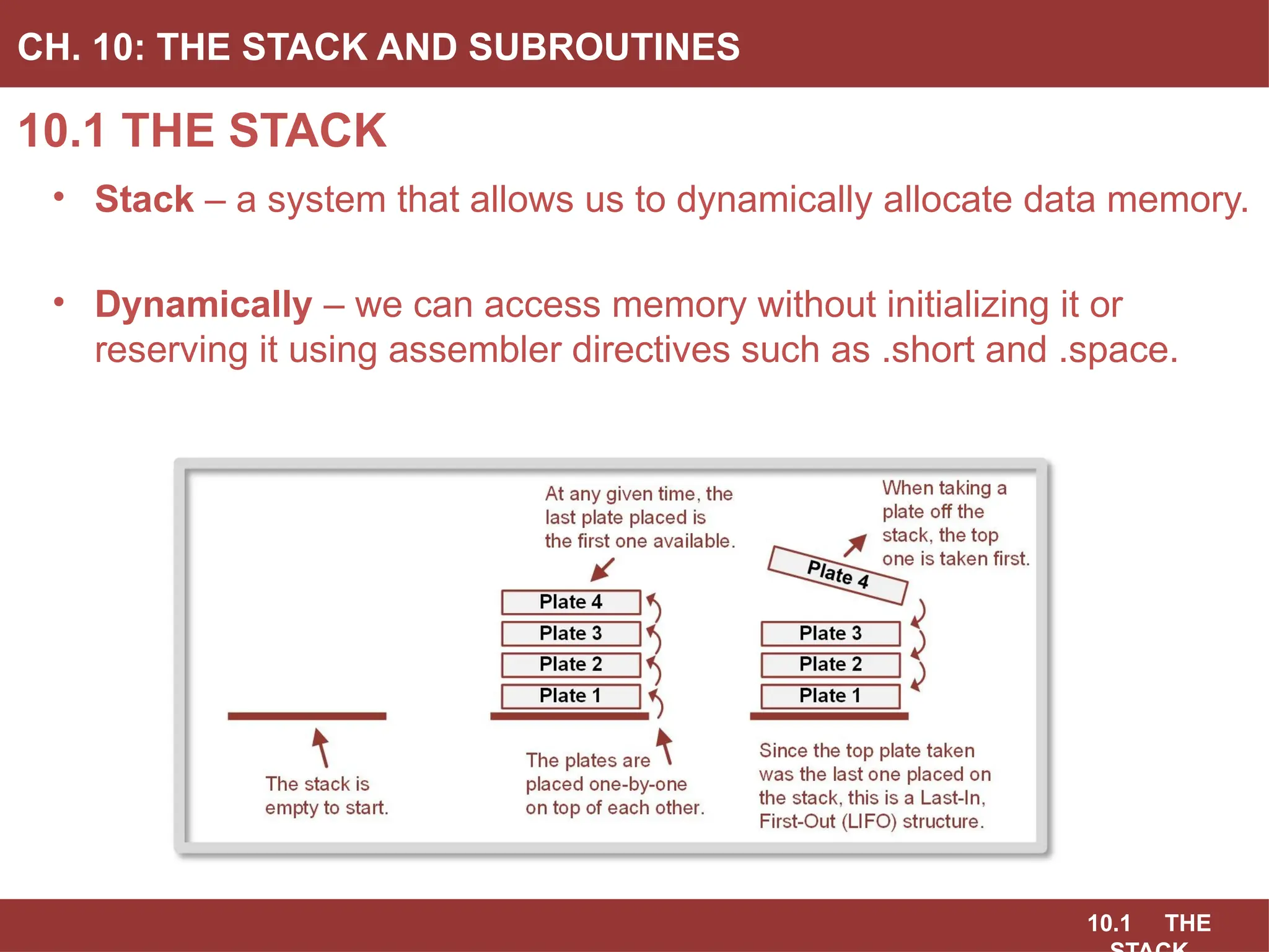
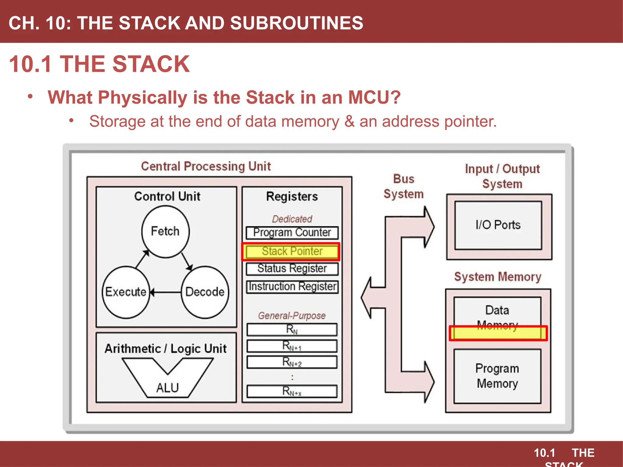
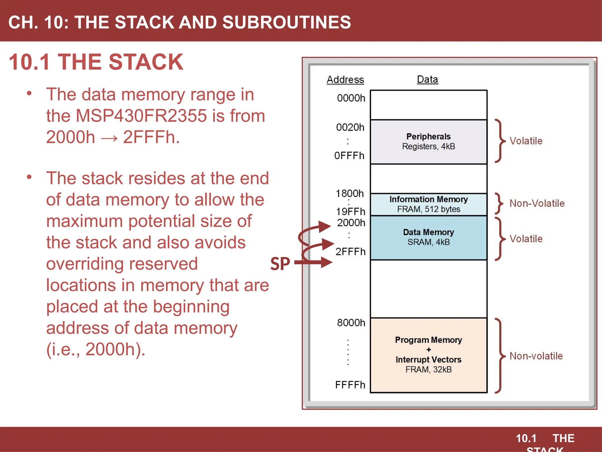
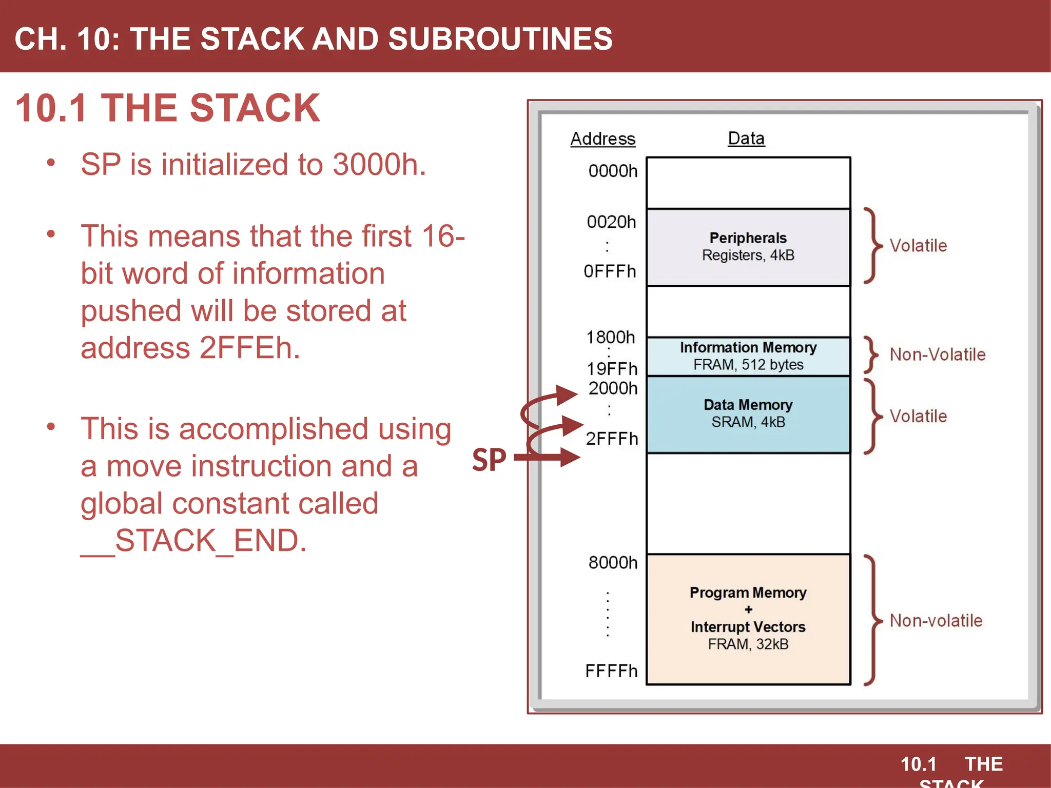
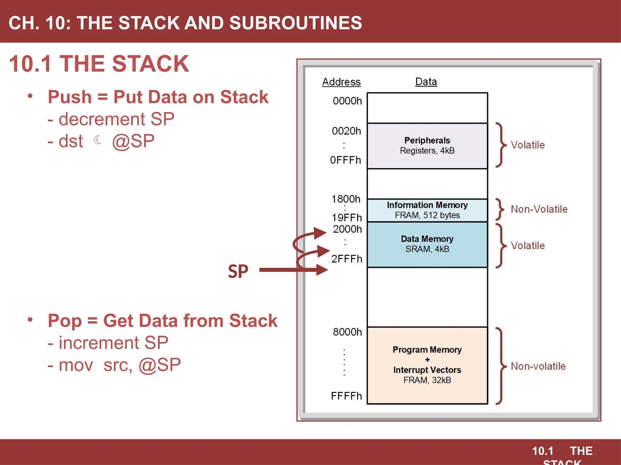
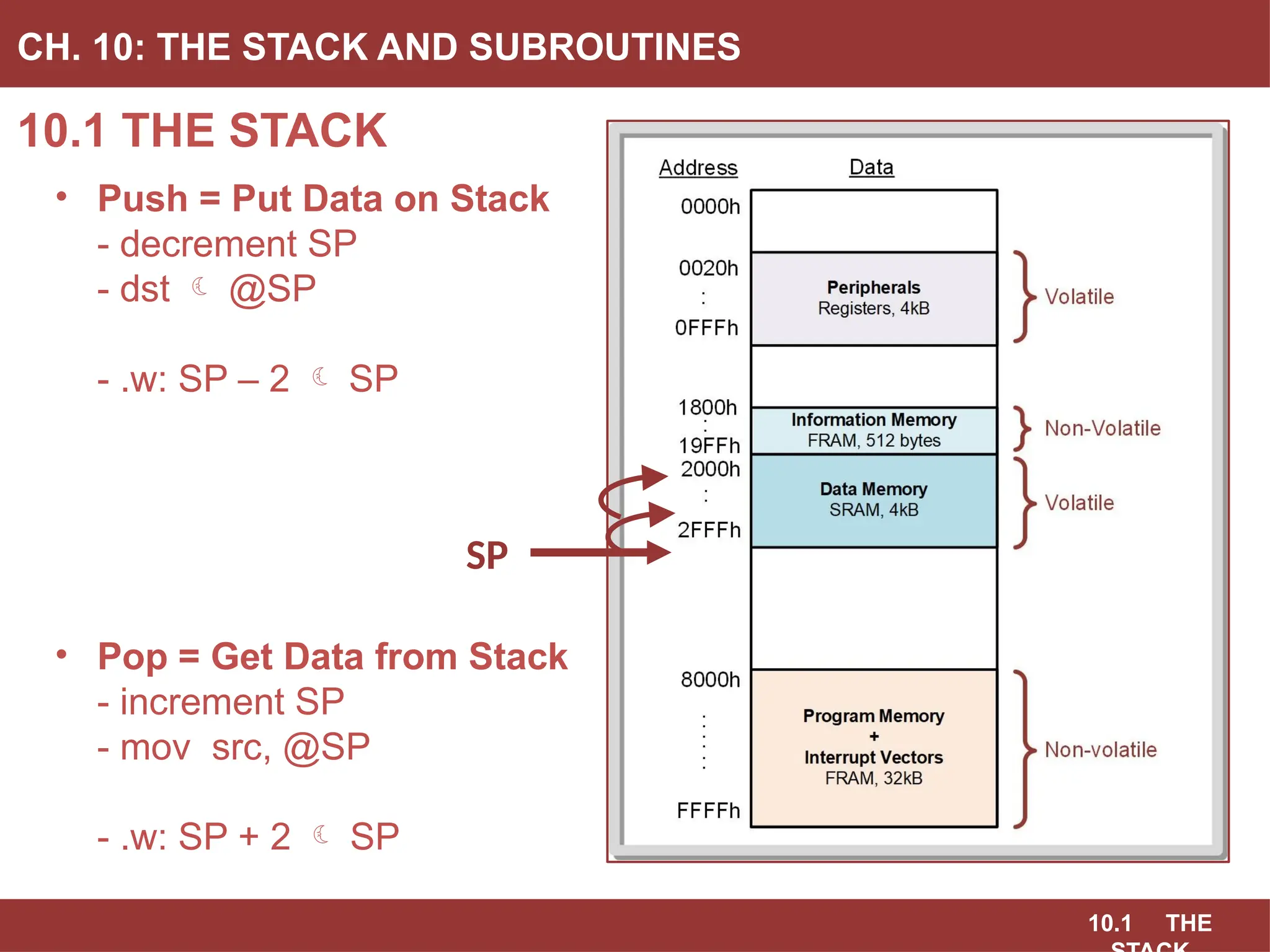
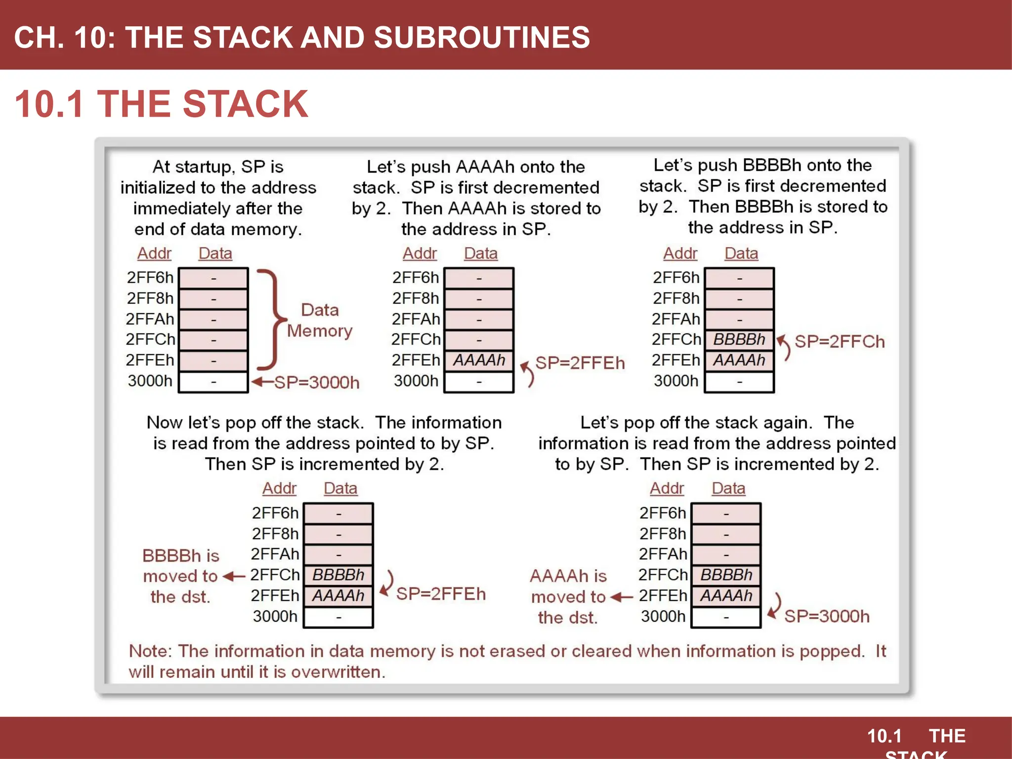
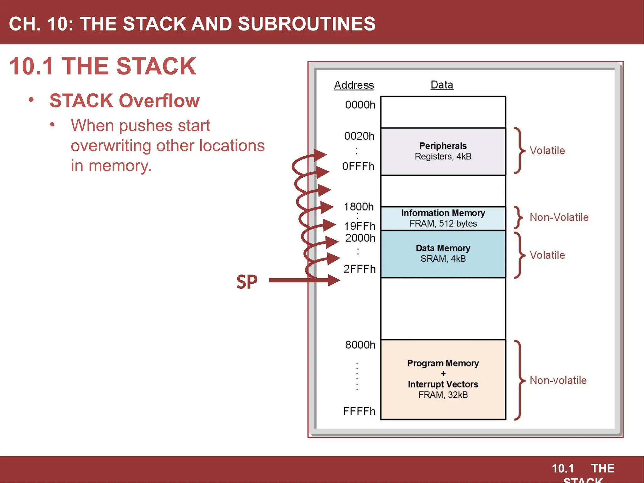
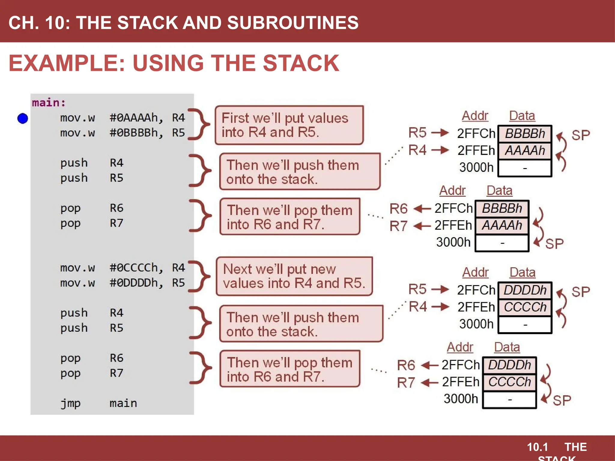
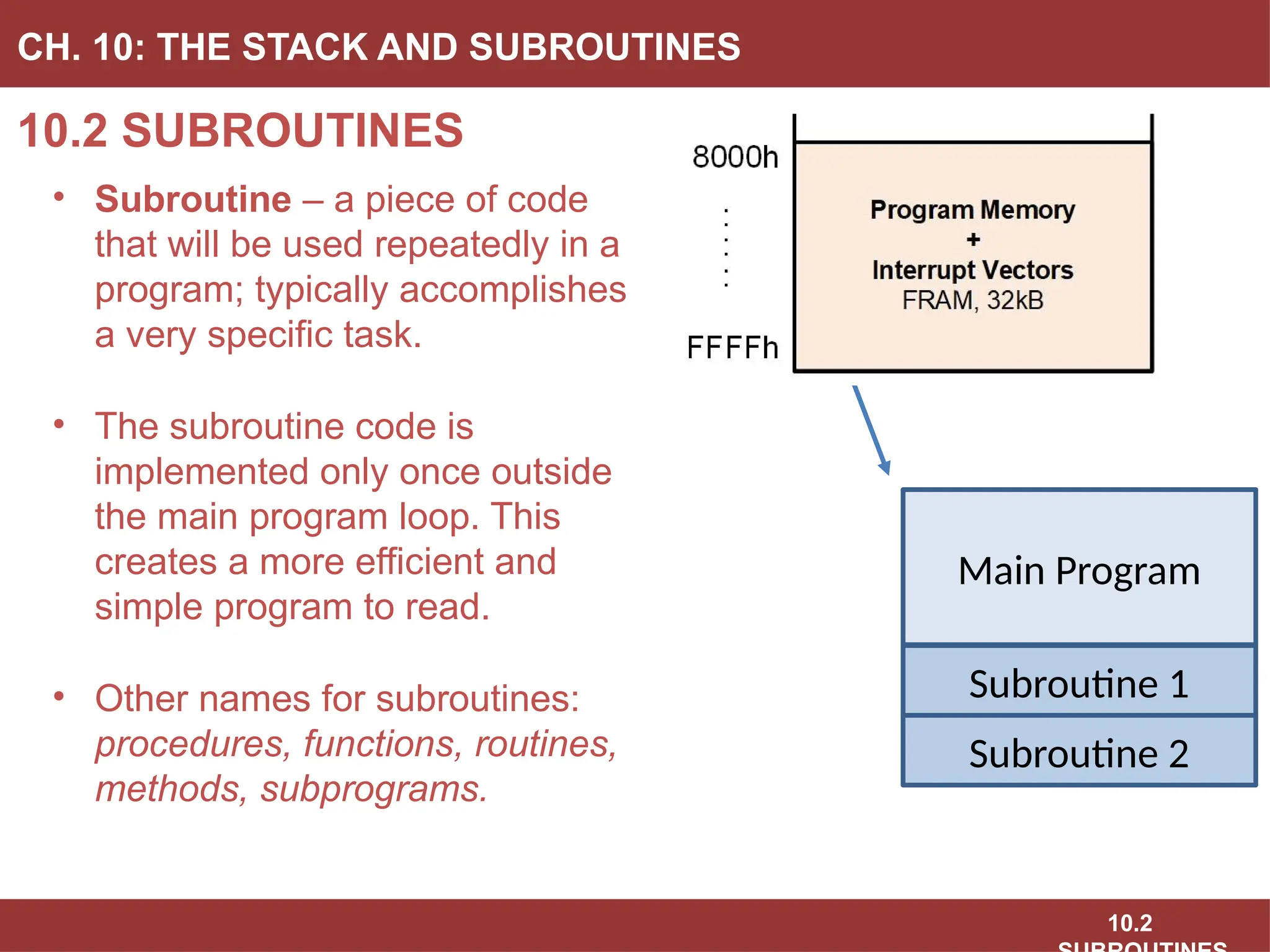
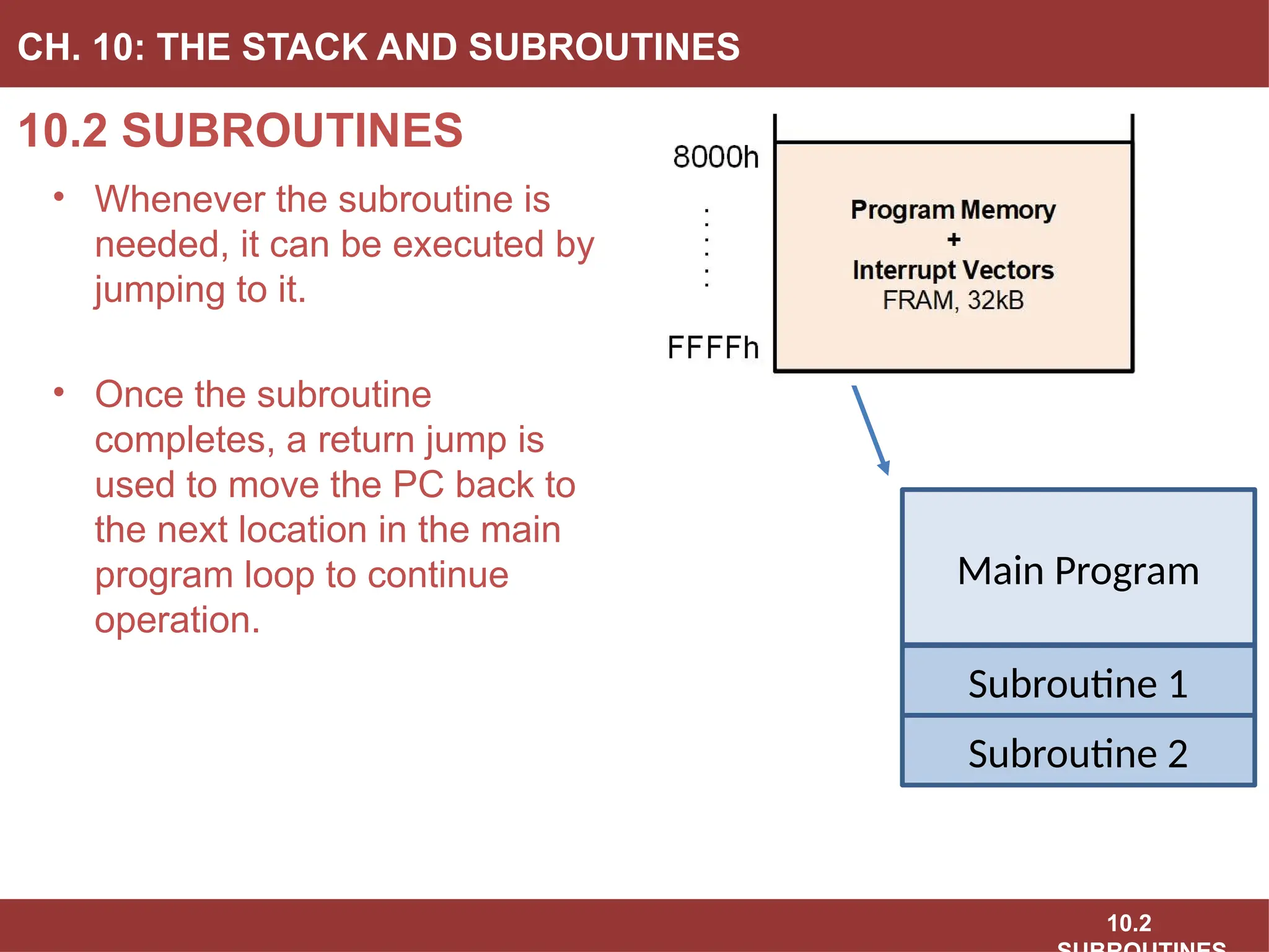
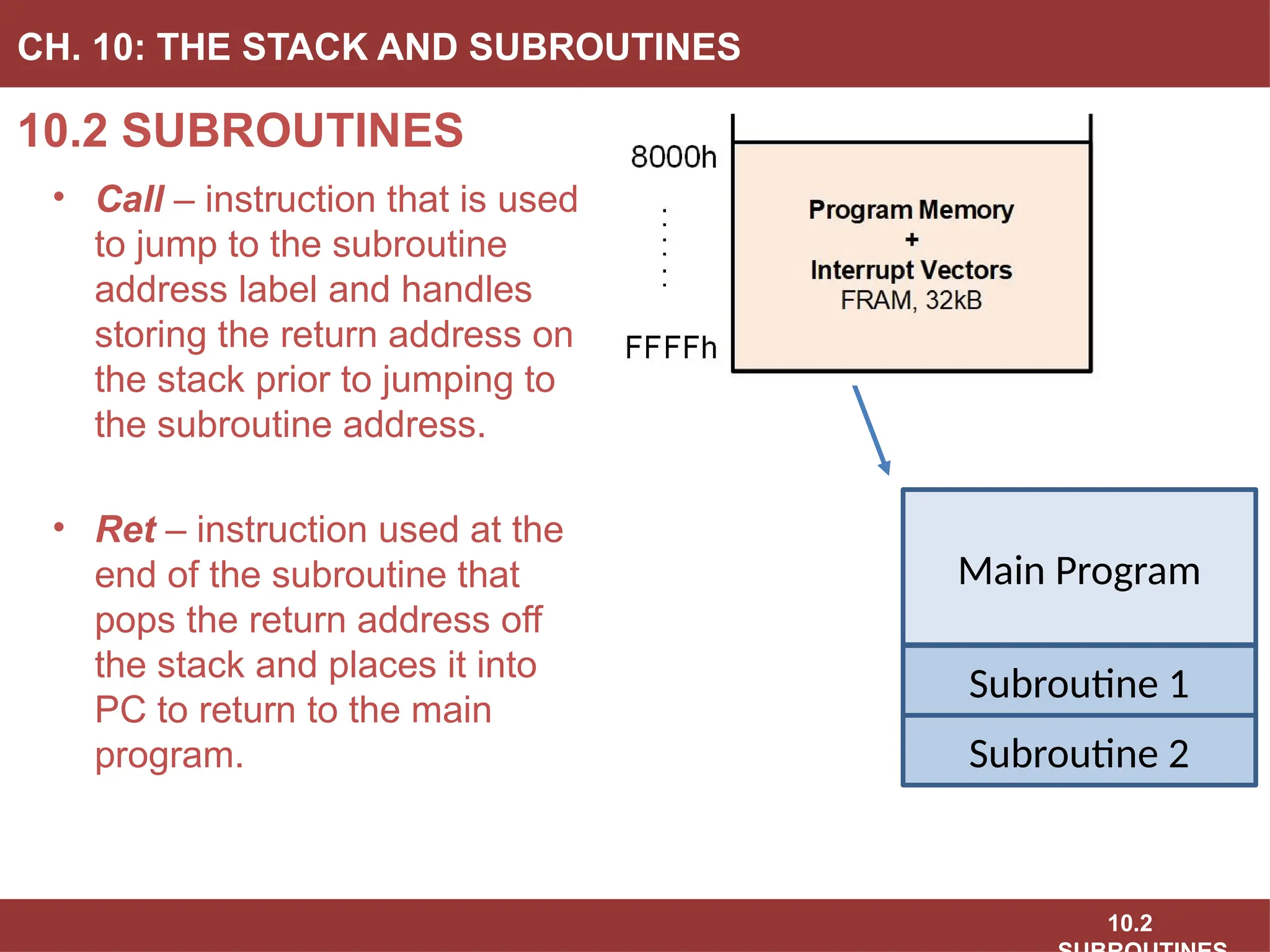
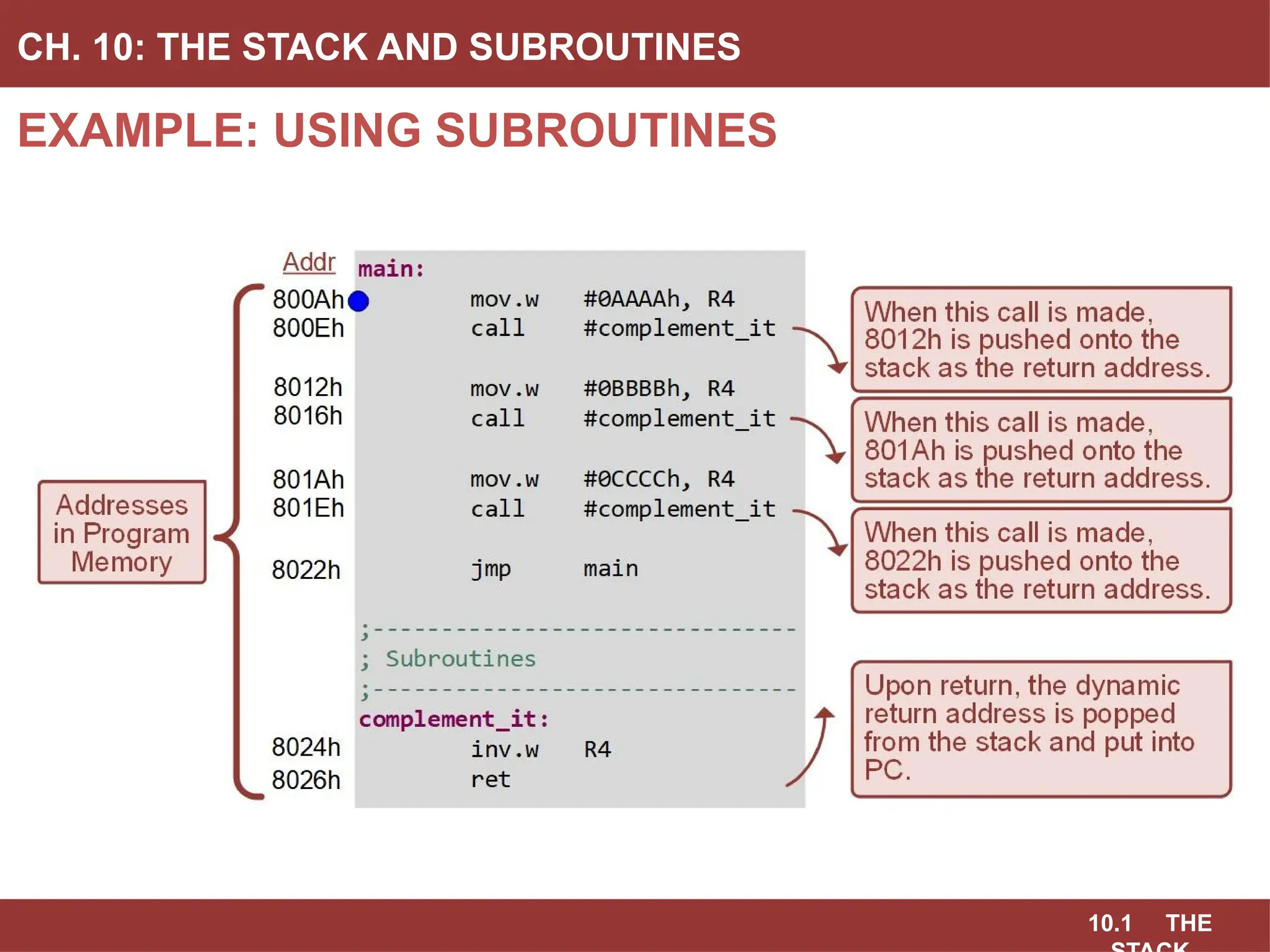
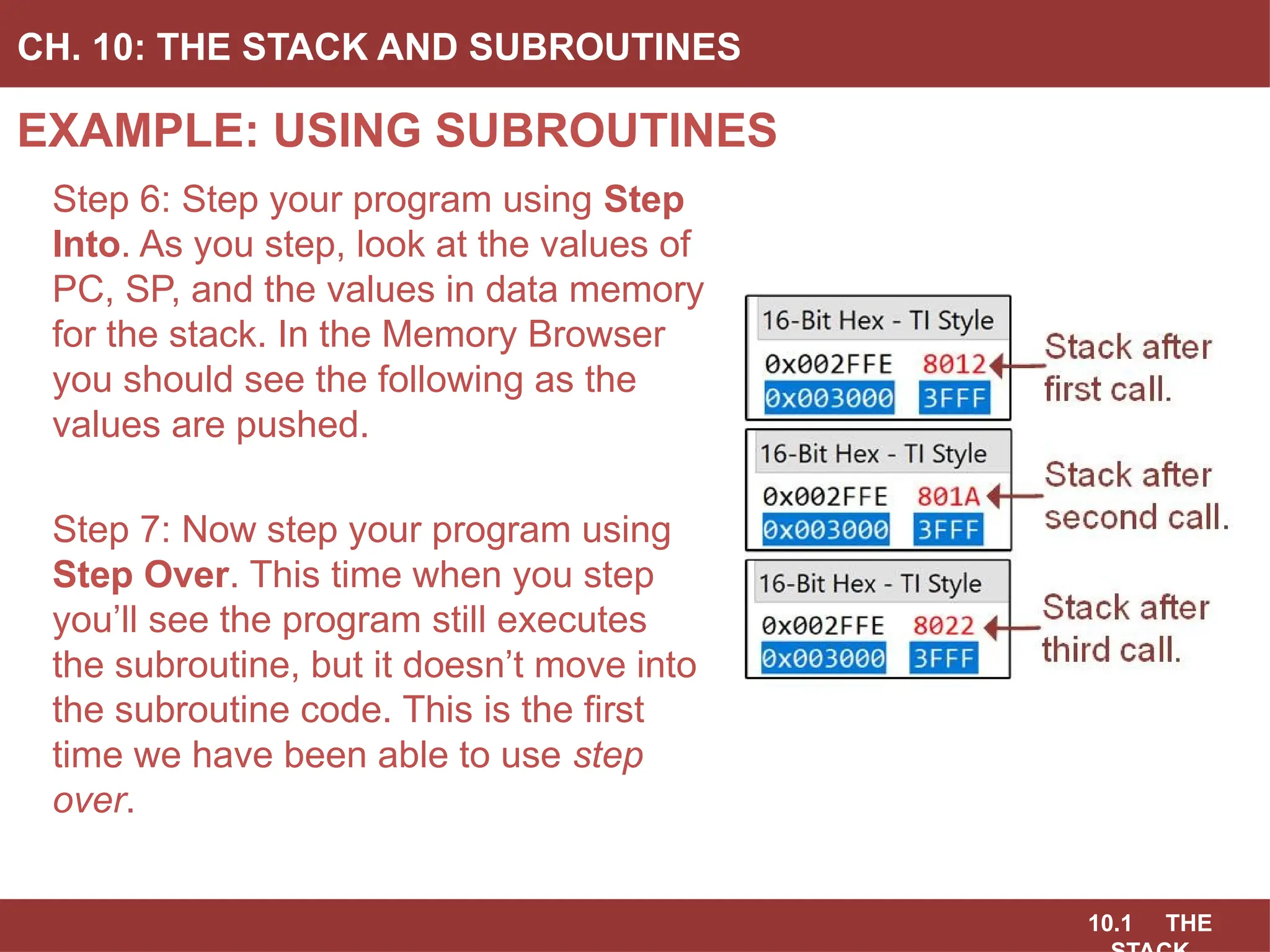
KEMBAR78
Ch10_The_STACK_and_Subroutines_Slides.pptx
BROCK J. LAMERES, PH.D.
CHAPTER 10: THE STACK AND SUBROUTINES
EMBEDDED SYSTEMS DESIGN
10.1 THE STACK
10.1 THE
10.1 THE STACK
CH. 10: THE STACK AND SUBROUTINES
• A stack is a last-in, first out (LIFO) storage structure.
10.1 THE
10.1 THE STACK
CH. 10: THE STACK AND SUBROUTINES
• Stack – a system that allows us to dynamically allocate data memory.
• Dynamically – we can access memory without initializing it or
reserving it using assembler directives such as .short and .space.
10.1 THE
10.1 THE STACK
CH. 10: THE STACK AND SUBROUTINES
• What Physically is the Stack in an MCU?
• Storage at the end of data memory & an address pointer.
10.1 THE
10.1 THE STACK
CH. 10: THE STACK AND SUBROUTINES
• The data memory range in
the MSP430FR2355 is from
2000h → 2FFFh.
• The stack resides at the end
of data memory to allow the
maximum potential size of
the stack and also avoids
overriding reserved
locations in memory that are
placed at the beginning
address of data memory
(i.e., 2000h).
SP
10.1 THE
10.1 THE STACK
CH. 10: THE STACK AND SUBROUTINES
• SP is initialized to 3000h.
• This means that the first 16-
bit word of information
pushed will be stored at
address 2FFEh.
• This is accomplished using
a move instruction and a
global constant called
__STACK_END.
SP
10.1 THE
10.1 THE STACK
CH. 10: THE STACK AND SUBROUTINES
• Push = Put Data on Stack
- decrement SP
- dst  @SP
• Pop = Get Data from Stack
- increment SP
- mov src, @SP
SP
10.1 THE
10.1 THE STACK
CH. 10: THE STACK AND SUBROUTINES
• Push = Put Data on Stack
- decrement SP
- dst  @SP
- .w: SP – 2  SP
• Pop = Get Data from Stack
- increment SP
- mov src, @SP
- .w: SP + 2  SP
SP
10.1 THE
10.1 THE STACK
CH. 10: THE STACK AND SUBROUTINES
10.1 THE
10.1 THE STACK
CH. 10: THE STACK AND SUBROUTINES
• STACK Overflow
• When pushes start
overwriting other locations
in memory.
SP
10.1 THE
EXAMPLE: USING THE STACK
CH. 10: THE STACK AND SUBROUTINES
10.1 THE
EXAMPLE: USING THE STACK
CH. 10: THE STACK AND SUBROUTINES
Image Courtesy of
Recording Connection of Canada
Step 1: Create a new Empty Assembly-only CCS project titled:
Asm_Stack
Step 2: Type in the following code into the main.asm file where the
comments say “Main loop here.”
Image Courtesy of
Recording Connection of Canada
Image Courtesy of
Recording Connection of Canada
Image Courtesy of
Recording Connection of Canada
Image Courtesy of https://neodem.wp.horizon.ac.uk/
10.1 THE
EXAMPLE: USING THE STACK
CH. 10: THE STACK AND SUBROUTINES
Image Courtesy of
Recording Connection of Canada
Step 3: Debug your program.
Step 4: Run your program to the breakpoint.
Step 5: Open the Register Viewer so that you can see SP and
R4 → R7. Open the Memory Browser and go to 0x3000. Then scroll up
so you can see the values 2FFEh and 2FFCh.
Image Courtesy of
Recording Connection of Canada
Image Courtesy of
Recording Connection of Canada
Image Courtesy of
Recording Connection of Canada
Image Courtesy of https://neodem.wp.horizon.ac.uk/
10.1 THE
EXAMPLE: USING THE STACK
CH. 10: THE STACK AND SUBROUTINES
Step 6: Step your program.
As you step, look at the
values of SP and the values
in data memory before
0x3000. In the Memory
Browser you should see the
following as the values are
pushed.
BROCK J. LAMERES, PH.D.
CHAPTER 10: THE STACK AND SUBROUTINES
EMBEDDED SYSTEMS DESIGN
10.1 THE STACK
www.youtube.com/c/DigitalLogicProgramming_LaMeres
BROCK J. LAMERES, PH.D.
CHAPTER 10: THE STACK AND SUBROUTINES
EMBEDDED SYSTEMS DESIGN
10.2 SUBROUTINES
10.2
10.2 SUBROUTINES
CH. 10: THE STACK AND SUBROUTINES
• Subroutine – a piece of code
that will be used repeatedly in a
program; typically accomplishes
a very specific task.
• The subroutine code is
implemented only once outside
the main program loop. This
creates a more efficient and
simple program to read.
• Other names for subroutines:
procedures, functions, routines,
methods, subprograms.
Main Program
Subroutine 1
Subroutine 2
10.2
10.2 SUBROUTINES
CH. 10: THE STACK AND SUBROUTINES
• Whenever the subroutine is
needed, it can be executed by
jumping to it.
• Once the subroutine
completes, a return jump is
used to move the PC back to
the next location in the main
program loop to continue
operation.
Main Program
Subroutine 1
Subroutine 2
10.2
10.2 SUBROUTINES
CH. 10: THE STACK AND SUBROUTINES
• A subroutine starts with an
address label to mark its
location in memory.
• Additional steps must be taken
when jumping to a subroutine
because while the starting
address of the subroutine is
always the same, the return
address in the main program
will vary depending on where
in the main program it is called.
Main Program
Subroutine 1
Subroutine 2
10.2
10.2 SUBROUTINES
CH. 10: THE STACK AND SUBROUTINES
• Call – instruction that is used
to jump to the subroutine
address label and handles
storing the return address on
the stack prior to jumping to
the subroutine address.
• Ret – instruction used at the
end of the subroutine that
pops the return address off
the stack and places it into
PC to return to the main
program.
Main Program
Subroutine 1
Subroutine 2
10.2
10.2 SUBROUTINES
CH. 10: THE STACK AND SUBROUTINES
• Variables can be passed to subroutines using three different
approaches:
• Using the CPU registers
• Using the stack
• Using dedicated variables in data memory
Image Courtesy of
Recording Connection of Canada
Image Courtesy of
Recording Connection of Canada
Image Courtesy of
Recording Connection of Canada
Image Courtesy of
Recording Connection of Canada
Image Courtesy of https://neodem.wp.horizon.ac.uk/
10.1 THE
EXAMPLE: USING SUBROUTINES
CH. 10: THE STACK AND SUBROUTINES
10.2
EXAMPLE: USING SUBROUTINES
CH. 10: THE STACK AND SUBROUTINES
Image Courtesy of
Recording Connection of Canada
Image Courtesy of
Recording Connection of Canada
Image Courtesy of
Recording Connection of Canada
Image Courtesy of
Recording Connection of Canada
Step 1: Create a new Empty Assembly-only CCS project titled:
Asm_Subroutines
Step 2: Type in the following code into the main.asm file where the
comments say “Main loop here.”
Image Courtesy of https://neodem.wp.horizon.ac.uk/
10.1 THE
EXAMPLE: USING SUBROUTINES
CH. 10: THE STACK AND SUBROUTINES
Image Courtesy of
Recording Connection of Canada
Step 3: Debug your program.
Step 4: Run your program to the breakpoint.
Step 5: Open the Register Viewer so that you can see PC, SP, and R4.
Open the Memory Browser and go to 0x3000. Then scroll up so you can
see the first location on the stack (address 2FFEh).
Image Courtesy of
Recording Connection of Canada
Image Courtesy of
Recording Connection of Canada
Image Courtesy of
Recording Connection of Canada
Image Courtesy of https://neodem.wp.horizon.ac.uk/
10.1 THE
EXAMPLE: USING SUBROUTINES
CH. 10: THE STACK AND SUBROUTINES
Step 6: Step your program using Step
Into. As you step, look at the values of
PC, SP, and the values in data memory
for the stack. In the Memory Browser
you should see the following as the
values are pushed.
Step 7: Now step your program using
Step Over. This time when you step
you’ll see the program still executes
the subroutine, but it doesn’t move into
the subroutine code. This is the first
time we have been able to use step
over.
10.1 THE
EXAMPLE: USING SUBROUTINES
CH. 10: THE STACK AND SUBROUTINES
Image Courtesy of
Recording Connection of Canada
Image Courtesy of
Recording Connection of Canada
Image Courtesy of
Recording Connection of Canada
Image Courtesy of
Recording Connection of Canada
Image Courtesy of https://neodem.wp.horizon.ac.uk/
BROCK J. LAMERES, PH.D.
CHAPTER 10: THE STACK AND SUBROUTINES
EMBEDDED SYSTEMS DESIGN
10.2 SUBROUTINES
www.youtube.com/c/DigitalLogicProgramming_LaMeres

Ch10_The_STACK_and_Subroutines_Slides.pptx

  • 1.
    BROCK J. LAMERES,PH.D. CHAPTER 10: THE STACK AND SUBROUTINES EMBEDDED SYSTEMS DESIGN 10.1 THE STACK
  • 2.
    10.1 THE 10.1 THESTACK CH. 10: THE STACK AND SUBROUTINES • A stack is a last-in, first out (LIFO) storage structure.
  • 3.
    10.1 THE 10.1 THESTACK CH. 10: THE STACK AND SUBROUTINES • Stack – a system that allows us to dynamically allocate data memory. • Dynamically – we can access memory without initializing it or reserving it using assembler directives such as .short and .space.
  • 4.
    10.1 THE 10.1 THESTACK CH. 10: THE STACK AND SUBROUTINES • What Physically is the Stack in an MCU? • Storage at the end of data memory & an address pointer.
  • 5.
    10.1 THE 10.1 THESTACK CH. 10: THE STACK AND SUBROUTINES • The data memory range in the MSP430FR2355 is from 2000h → 2FFFh. • The stack resides at the end of data memory to allow the maximum potential size of the stack and also avoids overriding reserved locations in memory that are placed at the beginning address of data memory (i.e., 2000h). SP
  • 6.
    10.1 THE 10.1 THESTACK CH. 10: THE STACK AND SUBROUTINES • SP is initialized to 3000h. • This means that the first 16- bit word of information pushed will be stored at address 2FFEh. • This is accomplished using a move instruction and a global constant called __STACK_END. SP
  • 7.
    10.1 THE 10.1 THESTACK CH. 10: THE STACK AND SUBROUTINES • Push = Put Data on Stack - decrement SP - dst  @SP • Pop = Get Data from Stack - increment SP - mov src, @SP SP
  • 8.
    10.1 THE 10.1 THESTACK CH. 10: THE STACK AND SUBROUTINES • Push = Put Data on Stack - decrement SP - dst  @SP - .w: SP – 2  SP • Pop = Get Data from Stack - increment SP - mov src, @SP - .w: SP + 2  SP SP
  • 9.
    10.1 THE 10.1 THESTACK CH. 10: THE STACK AND SUBROUTINES
  • 10.
    10.1 THE 10.1 THESTACK CH. 10: THE STACK AND SUBROUTINES • STACK Overflow • When pushes start overwriting other locations in memory. SP
  • 11.
    10.1 THE EXAMPLE: USINGTHE STACK CH. 10: THE STACK AND SUBROUTINES
  • 12.
    10.1 THE EXAMPLE: USINGTHE STACK CH. 10: THE STACK AND SUBROUTINES Image Courtesy of Recording Connection of Canada Step 1: Create a new Empty Assembly-only CCS project titled: Asm_Stack Step 2: Type in the following code into the main.asm file where the comments say “Main loop here.” Image Courtesy of Recording Connection of Canada Image Courtesy of Recording Connection of Canada Image Courtesy of Recording Connection of Canada Image Courtesy of https://neodem.wp.horizon.ac.uk/
  • 13.
    10.1 THE EXAMPLE: USINGTHE STACK CH. 10: THE STACK AND SUBROUTINES Image Courtesy of Recording Connection of Canada Step 3: Debug your program. Step 4: Run your program to the breakpoint. Step 5: Open the Register Viewer so that you can see SP and R4 → R7. Open the Memory Browser and go to 0x3000. Then scroll up so you can see the values 2FFEh and 2FFCh. Image Courtesy of Recording Connection of Canada Image Courtesy of Recording Connection of Canada Image Courtesy of Recording Connection of Canada Image Courtesy of https://neodem.wp.horizon.ac.uk/
  • 14.
    10.1 THE EXAMPLE: USINGTHE STACK CH. 10: THE STACK AND SUBROUTINES Step 6: Step your program. As you step, look at the values of SP and the values in data memory before 0x3000. In the Memory Browser you should see the following as the values are pushed.
  • 15.
    BROCK J. LAMERES,PH.D. CHAPTER 10: THE STACK AND SUBROUTINES EMBEDDED SYSTEMS DESIGN 10.1 THE STACK www.youtube.com/c/DigitalLogicProgramming_LaMeres
  • 16.
    BROCK J. LAMERES,PH.D. CHAPTER 10: THE STACK AND SUBROUTINES EMBEDDED SYSTEMS DESIGN 10.2 SUBROUTINES
  • 17.
    10.2 10.2 SUBROUTINES CH. 10:THE STACK AND SUBROUTINES • Subroutine – a piece of code that will be used repeatedly in a program; typically accomplishes a very specific task. • The subroutine code is implemented only once outside the main program loop. This creates a more efficient and simple program to read. • Other names for subroutines: procedures, functions, routines, methods, subprograms. Main Program Subroutine 1 Subroutine 2
  • 18.
    10.2 10.2 SUBROUTINES CH. 10:THE STACK AND SUBROUTINES • Whenever the subroutine is needed, it can be executed by jumping to it. • Once the subroutine completes, a return jump is used to move the PC back to the next location in the main program loop to continue operation. Main Program Subroutine 1 Subroutine 2
  • 19.
    10.2 10.2 SUBROUTINES CH. 10:THE STACK AND SUBROUTINES • A subroutine starts with an address label to mark its location in memory. • Additional steps must be taken when jumping to a subroutine because while the starting address of the subroutine is always the same, the return address in the main program will vary depending on where in the main program it is called. Main Program Subroutine 1 Subroutine 2
  • 20.
    10.2 10.2 SUBROUTINES CH. 10:THE STACK AND SUBROUTINES • Call – instruction that is used to jump to the subroutine address label and handles storing the return address on the stack prior to jumping to the subroutine address. • Ret – instruction used at the end of the subroutine that pops the return address off the stack and places it into PC to return to the main program. Main Program Subroutine 1 Subroutine 2
  • 21.
    10.2 10.2 SUBROUTINES CH. 10:THE STACK AND SUBROUTINES • Variables can be passed to subroutines using three different approaches: • Using the CPU registers • Using the stack • Using dedicated variables in data memory Image Courtesy of Recording Connection of Canada Image Courtesy of Recording Connection of Canada Image Courtesy of Recording Connection of Canada Image Courtesy of Recording Connection of Canada Image Courtesy of https://neodem.wp.horizon.ac.uk/
  • 22.
    10.1 THE EXAMPLE: USINGSUBROUTINES CH. 10: THE STACK AND SUBROUTINES
  • 23.
    10.2 EXAMPLE: USING SUBROUTINES CH.10: THE STACK AND SUBROUTINES Image Courtesy of Recording Connection of Canada Image Courtesy of Recording Connection of Canada Image Courtesy of Recording Connection of Canada Image Courtesy of Recording Connection of Canada Step 1: Create a new Empty Assembly-only CCS project titled: Asm_Subroutines Step 2: Type in the following code into the main.asm file where the comments say “Main loop here.” Image Courtesy of https://neodem.wp.horizon.ac.uk/
  • 24.
    10.1 THE EXAMPLE: USINGSUBROUTINES CH. 10: THE STACK AND SUBROUTINES Image Courtesy of Recording Connection of Canada Step 3: Debug your program. Step 4: Run your program to the breakpoint. Step 5: Open the Register Viewer so that you can see PC, SP, and R4. Open the Memory Browser and go to 0x3000. Then scroll up so you can see the first location on the stack (address 2FFEh). Image Courtesy of Recording Connection of Canada Image Courtesy of Recording Connection of Canada Image Courtesy of Recording Connection of Canada Image Courtesy of https://neodem.wp.horizon.ac.uk/
  • 25.
    10.1 THE EXAMPLE: USINGSUBROUTINES CH. 10: THE STACK AND SUBROUTINES Step 6: Step your program using Step Into. As you step, look at the values of PC, SP, and the values in data memory for the stack. In the Memory Browser you should see the following as the values are pushed. Step 7: Now step your program using Step Over. This time when you step you’ll see the program still executes the subroutine, but it doesn’t move into the subroutine code. This is the first time we have been able to use step over.
  • 26.
    10.1 THE EXAMPLE: USINGSUBROUTINES CH. 10: THE STACK AND SUBROUTINES Image Courtesy of Recording Connection of Canada Image Courtesy of Recording Connection of Canada Image Courtesy of Recording Connection of Canada Image Courtesy of Recording Connection of Canada Image Courtesy of https://neodem.wp.horizon.ac.uk/
  • 27.
    BROCK J. LAMERES,PH.D. CHAPTER 10: THE STACK AND SUBROUTINES EMBEDDED SYSTEMS DESIGN 10.2 SUBROUTINES www.youtube.com/c/DigitalLogicProgramming_LaMeres