NALLA MALLA REDDYENGINEERING COLLEGE
CADCAM
COMPUTER AIDED PROCESS PLANNING
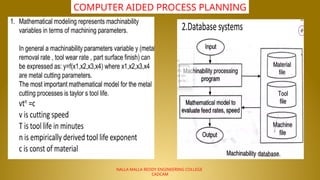
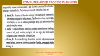
5.
NALLA MALLA REDDYENGINEERING COLLEGE
CADCAM
COMPUTER AIDED PROCESS PLANNING
6.
NALLA MALLA REDDYENGINEERING COLLEGE
CADCAM
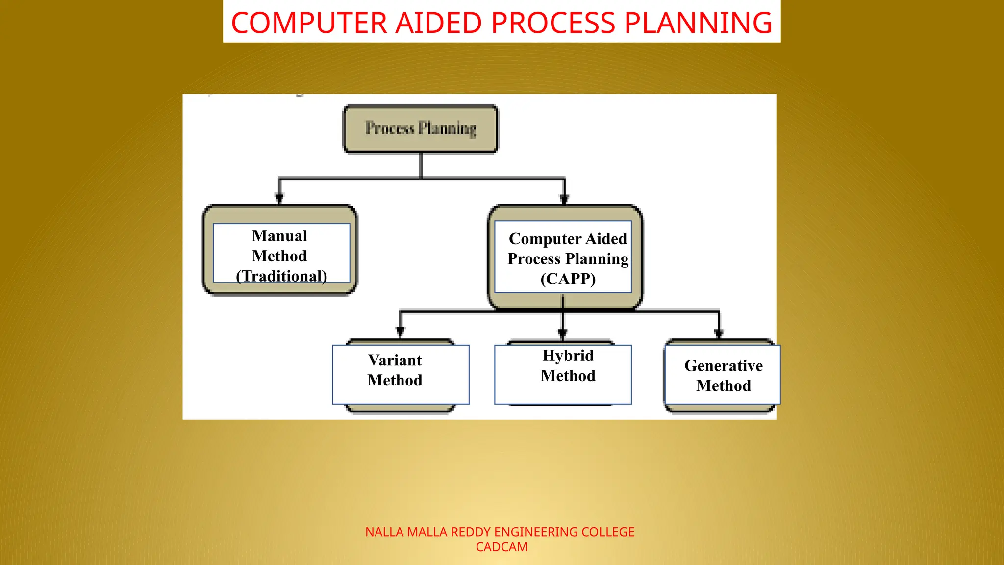
COMPUTER AIDED PROCESS PLANNING
Manual
Method
(Traditional)
Computer Aided
Process Planning
(CAPP)
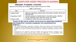
Variant
Method
Generative
Method
Hybrid
Method
7.
NALLA MALLA REDDYENGINEERING COLLEGE
CADCAM
COMPUTER AIDED PROCESS PLANNING
8.
NALLA MALLA REDDYENGINEERING COLLEGE
CADCAM
COMPUTER AIDED PROCESS PLANNING
9.
NALLA MALLA REDDYENGINEERING COLLEGE
CADCAM
COMPUTER AIDED PROCESS PLANNING
10.
NALLA MALLA REDDYENGINEERING COLLEGE
CADCAM
COMPUTER AIDED PROCESS PLANNING
11.
NALLA MALLA REDDYENGINEERING COLLEGE
CADCAM
COMPUTER AIDED PROCESS PLANNING
12.
NALLA MALLA REDDYENGINEERING COLLEGE
CADCAM
COMPUTER AIDED PROCESS PLANNING
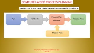
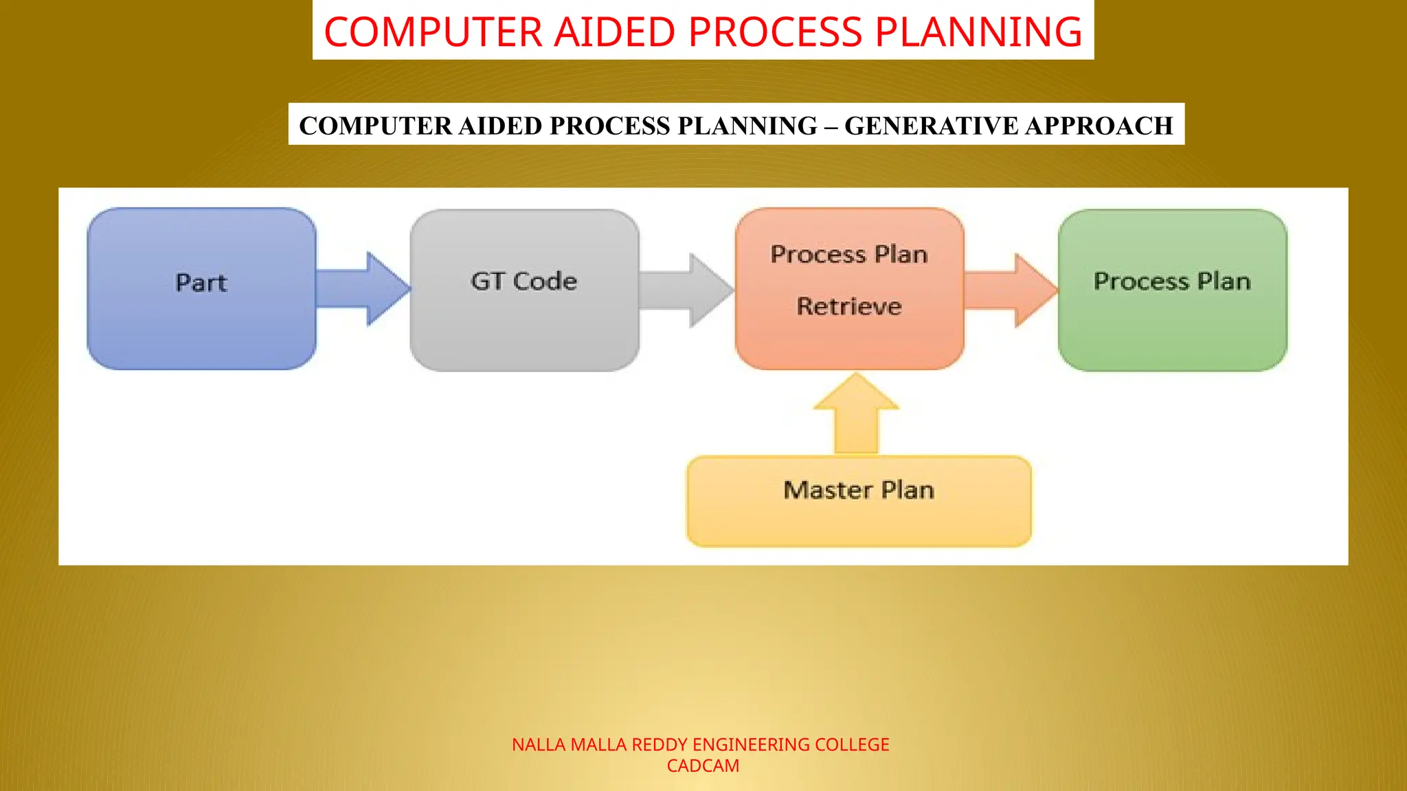
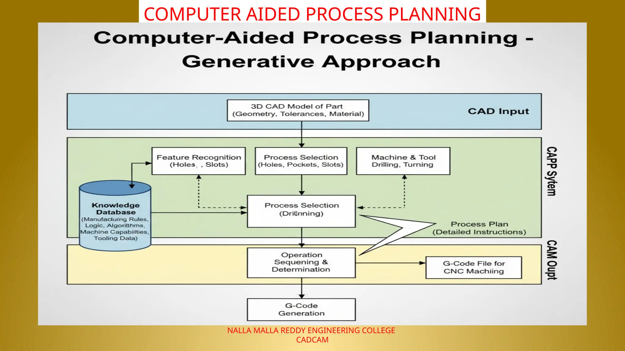
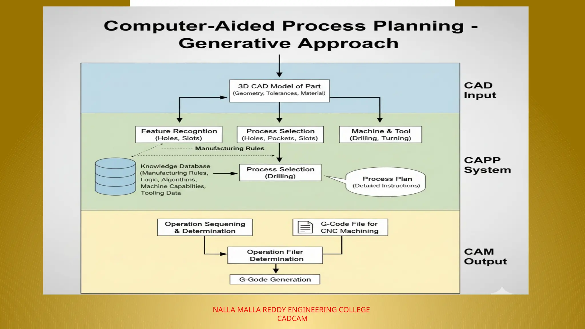
COMPUTER AIDED PROCESS PLANNING – GENERATIVE APPROACH
13.
NALLA MALLA REDDYENGINEERING COLLEGE
CADCAM
COMPUTER AIDED PROCESS PLANNING
14.
NALLA MALLA REDDYENGINEERING COLLEGE
CADCAM
COMPUTER AIDED PROCESS PLANNING
15.
NALLA MALLA REDDYENGINEERING COLLEGE
CADCAM
COMPUTER AIDED PROCESS PLANNING
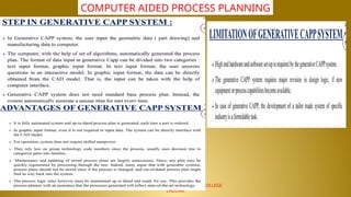
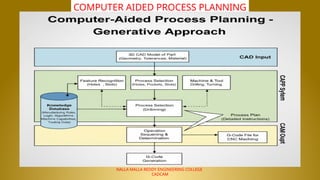
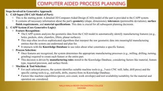
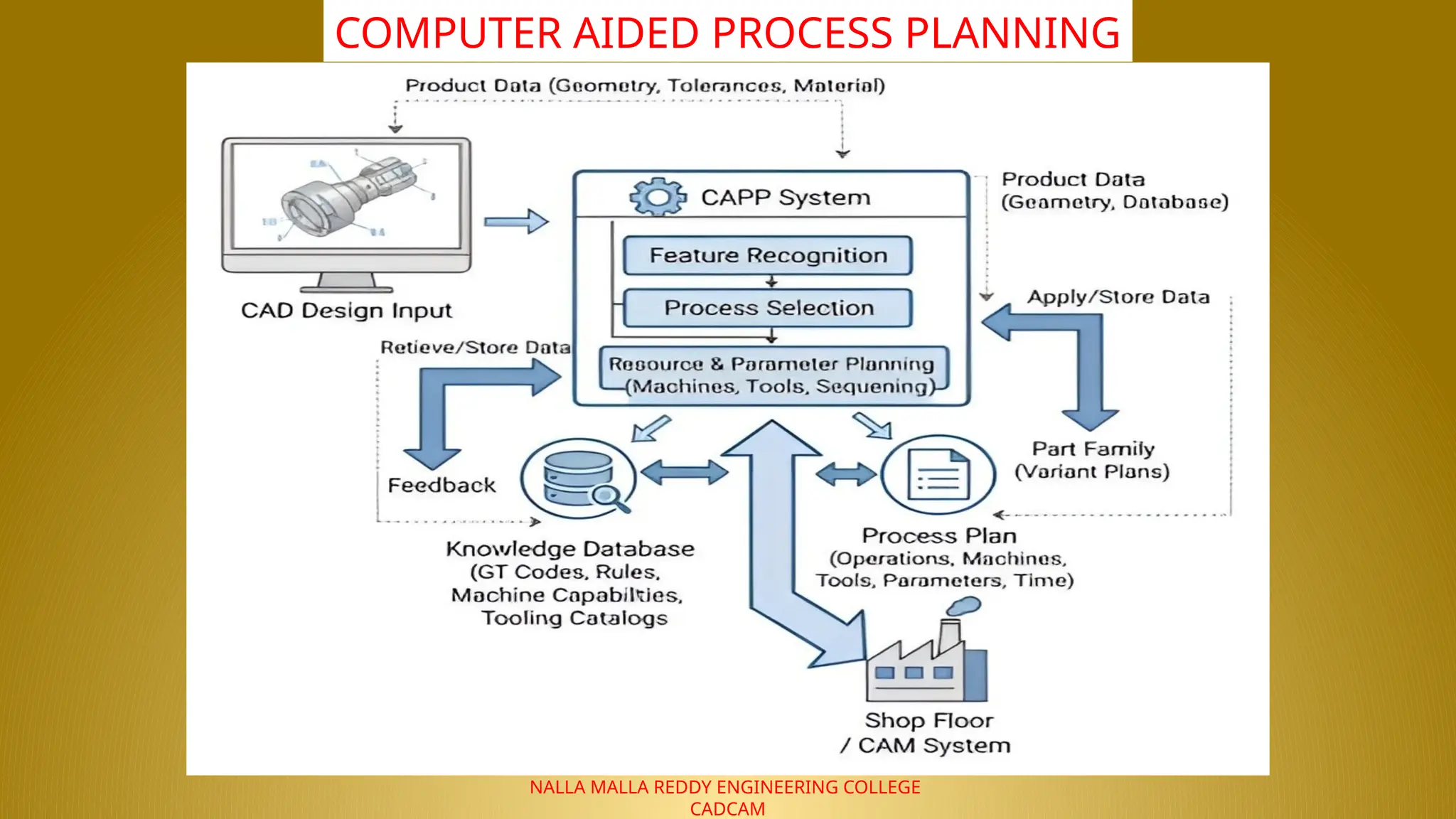
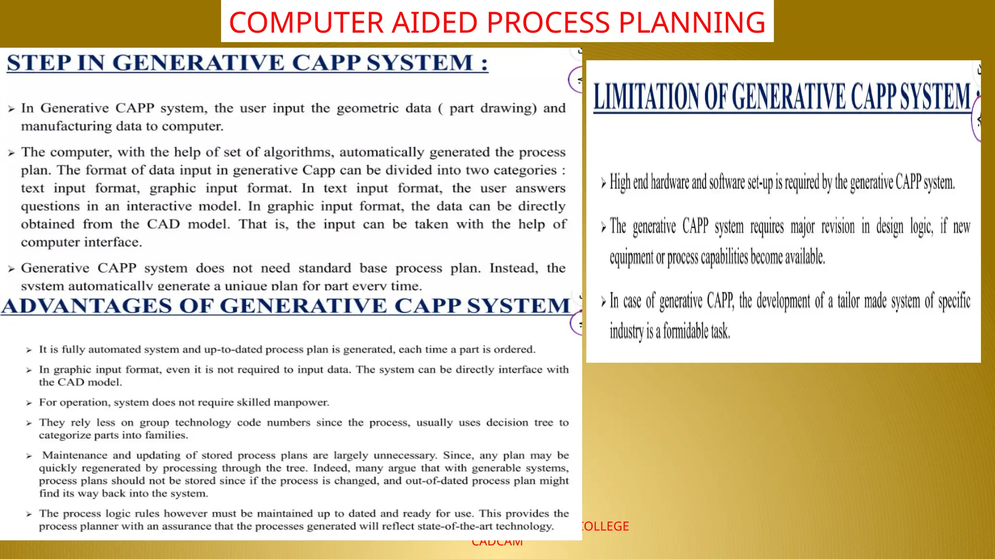
Steps Involved in Generative Approach:
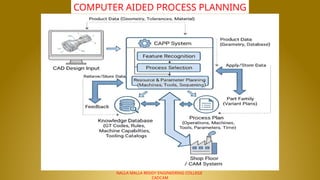
1. CAD Input (3D CAD Model of Part):
o This is the starting point. A detailed 3D Computer-Aided Design (CAD) model of the part is provided to the CAPP system.
o It contains all necessary information about the part's geometry (shape, dimensions), tolerances (permissible deviations), surface
finish requirements, and material specifications. This data is crucial for all subsequent planning decisions.
2. CAPP System (Core Generative Logic):
o Feature Recognition:
The CAPP system analyzes the geometric data from the CAD model to automatically identify manufacturing features (ee.g.,
holes, pockets, slots, chamfers, fillets, planar surfaces).
This step often involves sophisticated algorithms that interpret the raw geometric data into meaningful manufacturing
entities that the system can understand and plan for.
It interacts with the Knowledge Database to use rules about what constitutes a specific feature.
o Process Selection:
Once features are recognized, the system determines the appropriate manufacturing processes (e.g., milling, drilling, turning,
grinding) required to create each feature or the entire part.
This decision is driven by manufacturing rules stored in the Knowledge Database, considering factors like material, feature
type, required precision, and surface finish.
o Machine & Tool Selection:
For each selected process, the system identifies suitable machine tools (e.g., 3-axis CNC mill, lathe, drill press) and the
specific cutting tools (e.g., end mills, drills, inserts) from its Knowledge Database.
Factors like machine capabilities (power, axis count, work envelope) and tool availability/suitability for the material and
operation are considered.
16.
NALLA MALLA REDDYENGINEERING COLLEGE
CADCAM
COMPUTER AIDED PROCESS PLANNING
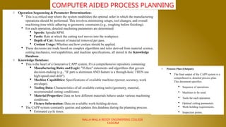
o Operation Sequencing & Parameter Determination:
This is a critical step where the system establishes the optimal order in which the manufacturing
operations should be performed. This involves minimizing setups, tool changes, and overall
machining time while adhering to geometric constraints (e.g., roughing before finishing).
For each operation, detailed machining parameters are determined:
Speeds: Spindle RPM.
Feeds: Rate at which the cutting tool moves into the workpiece.
Depth of Cut: Amount of material removed per pass.
Coolant Usage: Whether and how coolant should be applied.
These decisions are made based on complex algorithms and rules derived from material science,
cutting mechanics, tool capabilities, and machine specifications, all stored in the Knowledge
Database.
o Knowledge Database:
This is the heart of a Generative CAPP system. It's a comprehensive repository containing:
Manufacturing Rules and Logic: "If-then" statements and algorithms that govern
decision-making (e.g., "IF part is aluminum AND feature is a through-hole, THEN use
high-speed steel drill").
Machine Capabilities: Specifications of available machines (power, accuracy, work
envelope).
Tooling Data: Characteristics of all available cutting tools (geometry, material,
recommended cutting conditions).
Material Properties: Data on how different materials behave under various machining
conditions.
Fixture Information: Data on available work-holding devices.
The CAPP system constantly queries and updates this database during the planning process.
Estimated cycle times.
o Process Plan (Output):
The final output of the CAPP system is a
comprehensive, detailed process plan.
This document specifies:
Sequence of operations.
Machines to be used.
Tools for each operation.
Optimal cutting parameters.
Work-holding requirements.
Inspection points.
17.
NALLA MALLA REDDYENGINEERING COLLEGE
CADCAM
COMPUTER AIDED PROCESS PLANNING
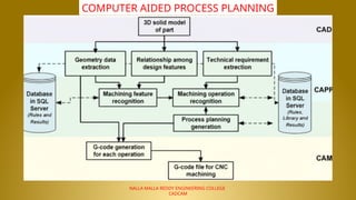
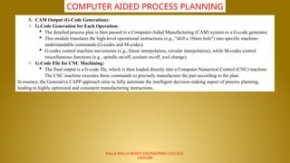
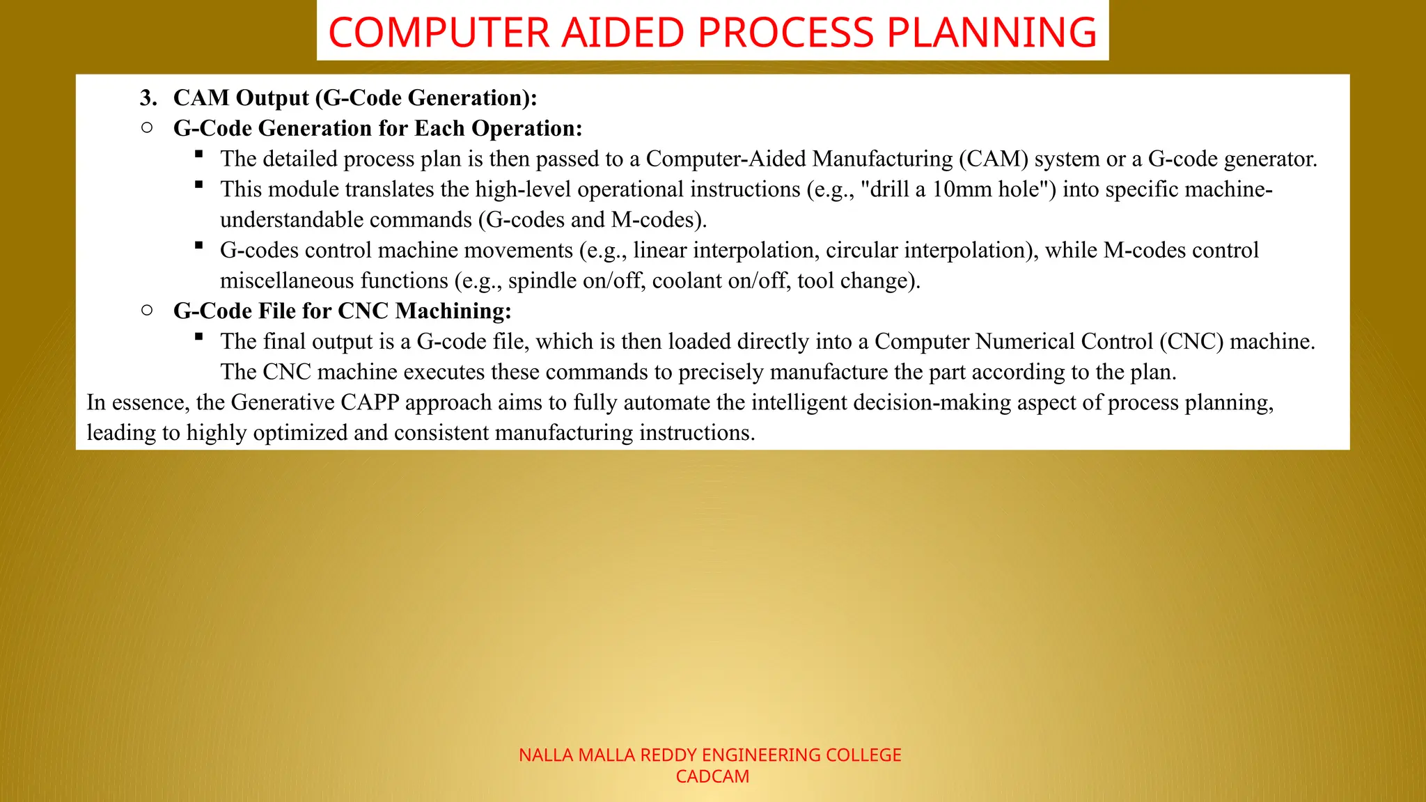
3. CAM Output (G-Code Generation):
o G-Code Generation for Each Operation:
The detailed process plan is then passed to a Computer-Aided Manufacturing (CAM) system or a G-code generator.
This module translates the high-level operational instructions (e.g., "drill a 10mm hole") into specific machine-
understandable commands (G-codes and M-codes).
G-codes control machine movements (e.g., linear interpolation, circular interpolation), while M-codes control
miscellaneous functions (e.g., spindle on/off, coolant on/off, tool change).
o G-Code File for CNC Machining:
The final output is a G-code file, which is then loaded directly into a Computer Numerical Control (CNC) machine.
The CNC machine executes these commands to precisely manufacture the part according to the plan.
In essence, the Generative CAPP approach aims to fully automate the intelligent decision-making aspect of process planning,
leading to highly optimized and consistent manufacturing instructions.
18.
NALLA MALLA REDDYENGINEERING COLLEGE
CADCAM
COMPUTER AIDED PROCESS PLANNING
19.
NALLA MALLA REDDYENGINEERING COLLEGE
CADCAM
COMPUTER AIDED PROCESS PLANNING
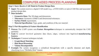
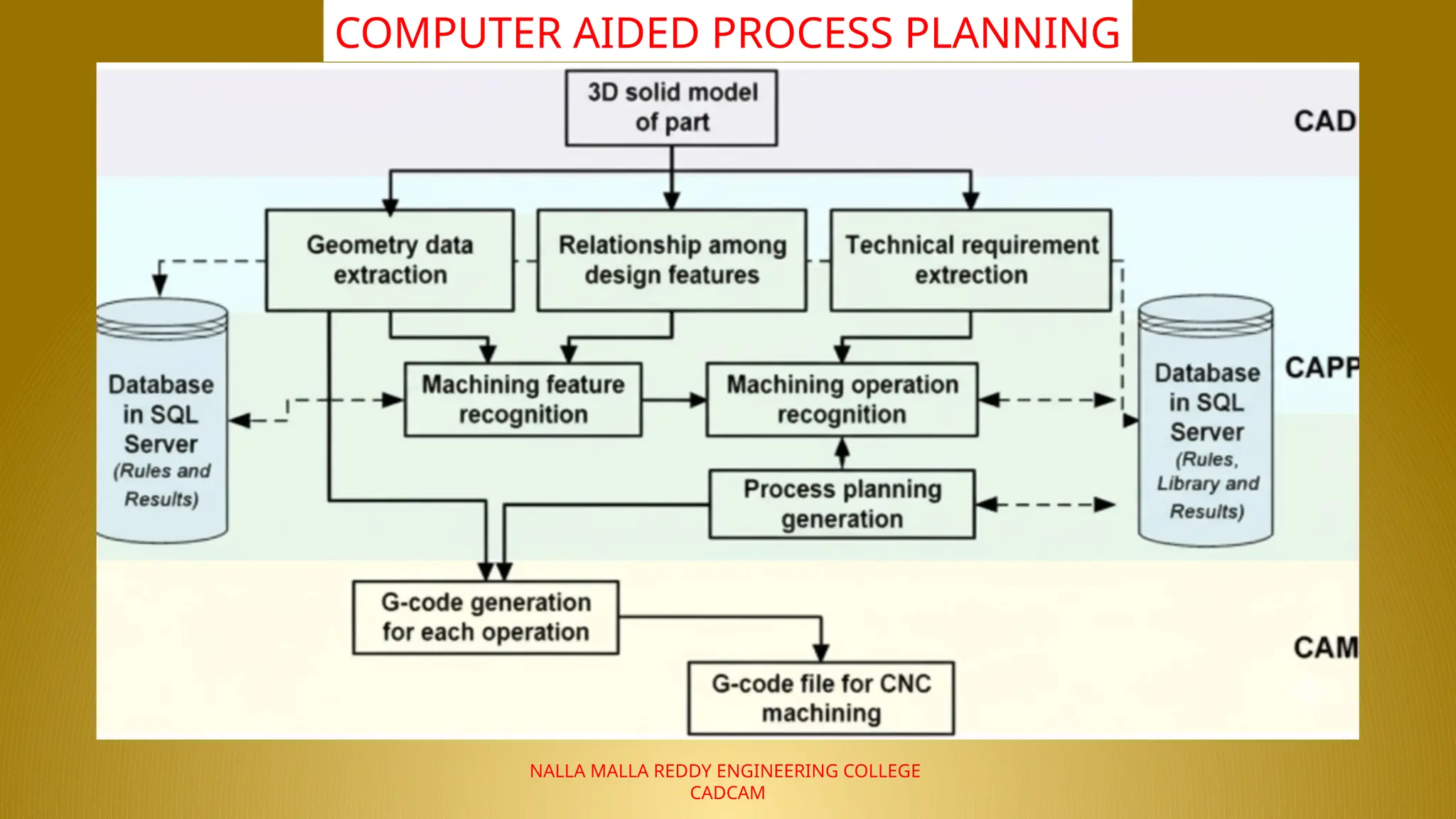
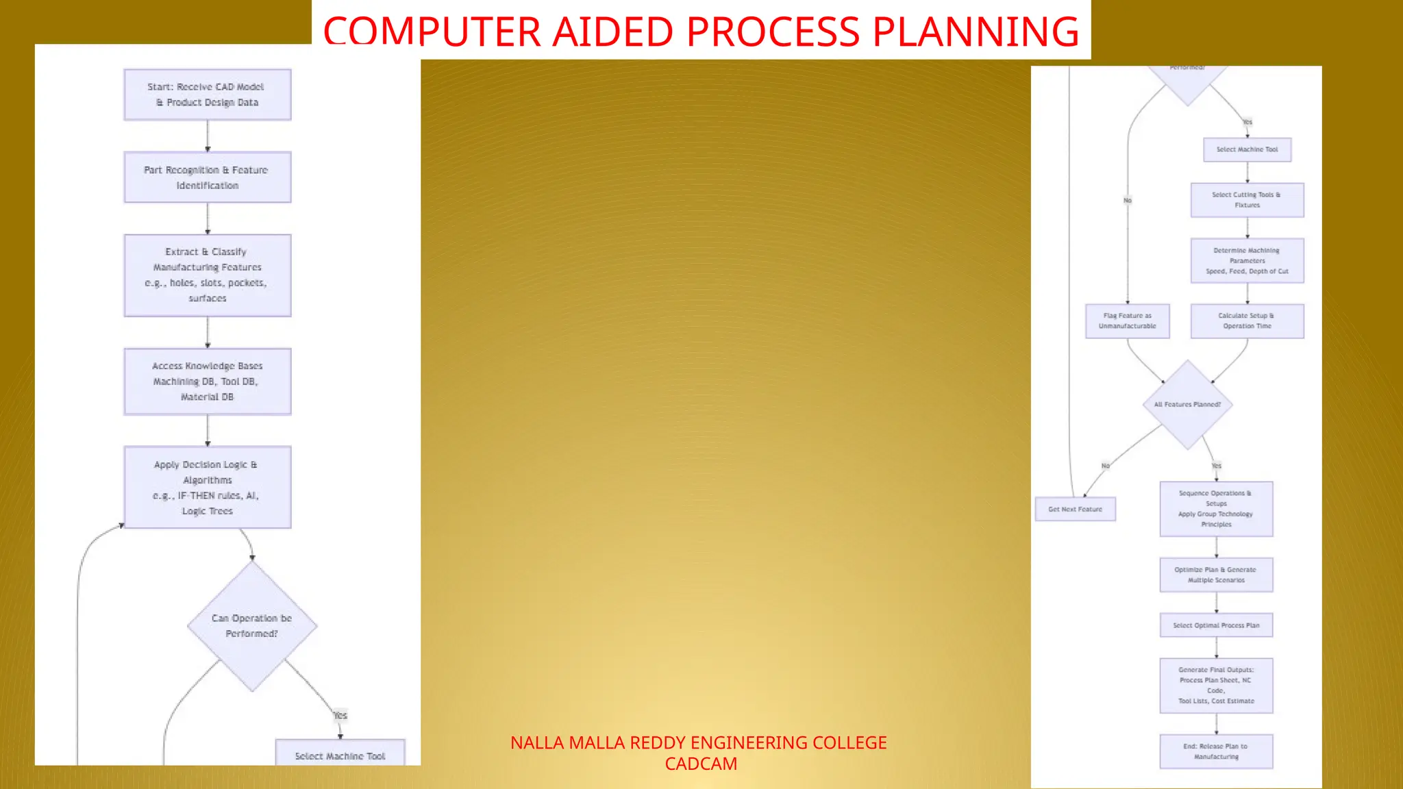
Step 1: Start: Receive CAD Model & Product Design Data
Input: The system receives a digital CAD model (e.g., a STEP, IGES, or native CAD file) and associated
product design data.
Data Includes:
o Geometric Data: The 3D shape and dimensions.
o Tolerances: Geometric (GD&T) and dimensional tolerances.
o Surface Finish requirements.
o Material Specification: Type, grade, and condition of the raw material.
Step 2: Part Recognition & Feature Identification
Process: The CAPP system uses Feature Recognition techniques to automatically interpret the CAD
geometry.
Goal: To convert low-level geometric data (faces, edges, vertices) into high-level manufacturing
features.
Techniques: Common techniques include:
o Graph-Based Matching
o Hint-Based Reasoning
o Volume Decomposition
Example: The system recognizes a cylindrical through-hole with a specific diameter and depth,
classifying it as a "Drillable Hole" feature.
20.
NALLA MALLA REDDYENGINEERING COLLEGE
CADCAM
COMPUTER AIDED PROCESS PLANNING
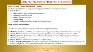
Step 3: Extract & Classify Manufacturing Features
The recognized features are categorized into a predefined library of manufacturing features.
Feature Types:
o Holes: Through holes, blind holes, threaded holes.
o Pockets: Rectangular, circular.
o Slots: T-slots, dovetail slots.
o Steps & Faces.
o Complex Surfaces: Freeform surfaces for 5-axis machining.
Step 4: Access Knowledge Bases
This is the core of the generative system. It consults several integrated databases:
Machining Database: Capabilities of available machines (e.g., max spindle speed, travel, horsepower, accuracy).
Tooling Database: Details on available cutting tools (e.g., drill bit sizes, end mill types, inserts, tool holders).
Material Database: Machinability data for different materials (e.g., recommended cutting speeds and feeds for
aluminum vs. titanium).
Fixture Database: Information on standard and available fixtures.
Rules & Logic Knowledge Base: The "brain" containing the manufacturing rules and decision-making logic (e.g., "IF
feature is a blind hole, THEN operation sequence must be Center Drill, Drill, Bore").
21.
NALLA MALLA REDDYENGINEERING COLLEGE
CADCAM
COMPUTER AIDED PROCESS PLANNING
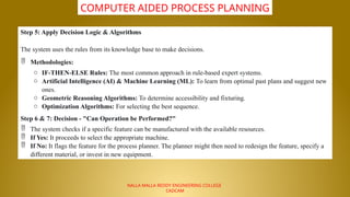
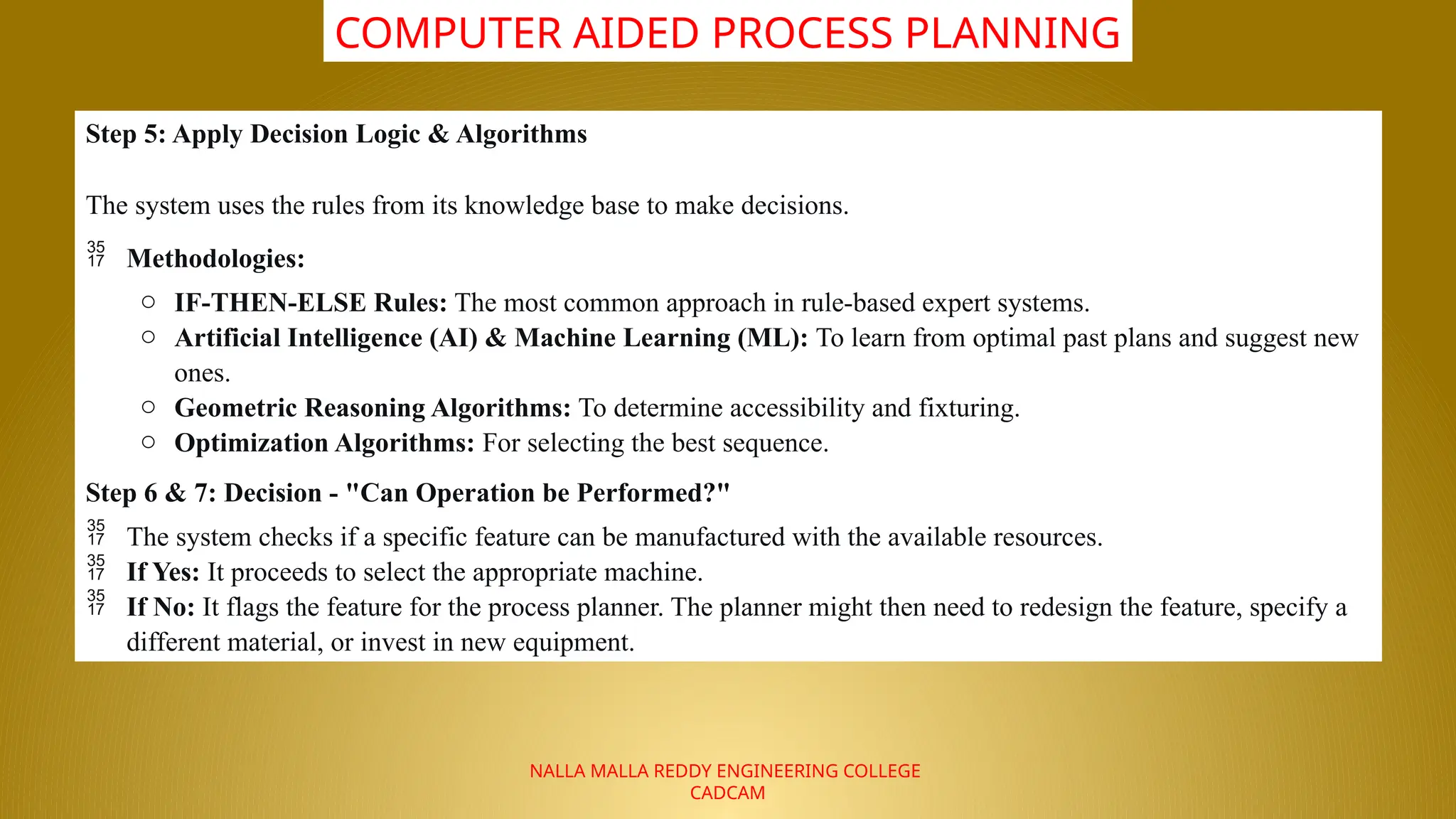
Step 5: Apply Decision Logic & Algorithms
The system uses the rules from its knowledge base to make decisions.
Methodologies:
o IF-THEN-ELSE Rules: The most common approach in rule-based expert systems.
o Artificial Intelligence (AI) & Machine Learning (ML): To learn from optimal past plans and suggest new
ones.
o Geometric Reasoning Algorithms: To determine accessibility and fixturing.
o Optimization Algorithms: For selecting the best sequence.
Step 6 & 7: Decision - "Can Operation be Performed?"
The system checks if a specific feature can be manufactured with the available resources.
If Yes: It proceeds to select the appropriate machine.
If No: It flags the feature for the process planner. The planner might then need to redesign the feature, specify a
different material, or invest in new equipment.
22.
NALLA MALLA REDDYENGINEERING COLLEGE
CADCAM
COMPUTER AIDED PROCESS PLANNING
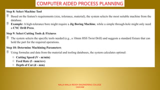
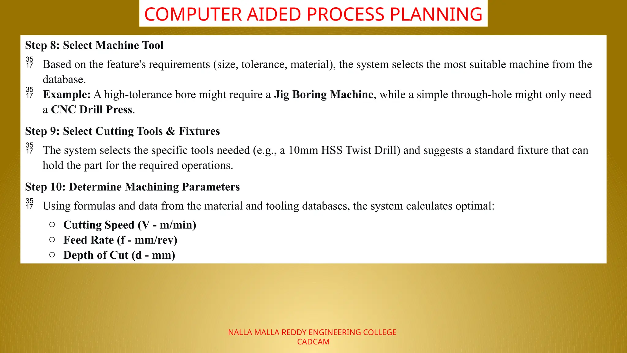
Step 8: Select Machine Tool
Based on the feature's requirements (size, tolerance, material), the system selects the most suitable machine from the
database.
Example: A high-tolerance bore might require a Jig Boring Machine, while a simple through-hole might only need
a CNC Drill Press.
Step 9: Select Cutting Tools & Fixtures
The system selects the specific tools needed (e.g., a 10mm HSS Twist Drill) and suggests a standard fixture that can
hold the part for the required operations.
Step 10: Determine Machining Parameters
Using formulas and data from the material and tooling databases, the system calculates optimal:
o Cutting Speed (V - m/min)
o Feed Rate (f - mm/rev)
o Depth of Cut (d - mm)
23.
NALLA MALLA REDDYENGINEERING COLLEGE
CADCAM
COMPUTER AIDED PROCESS PLANNING
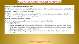
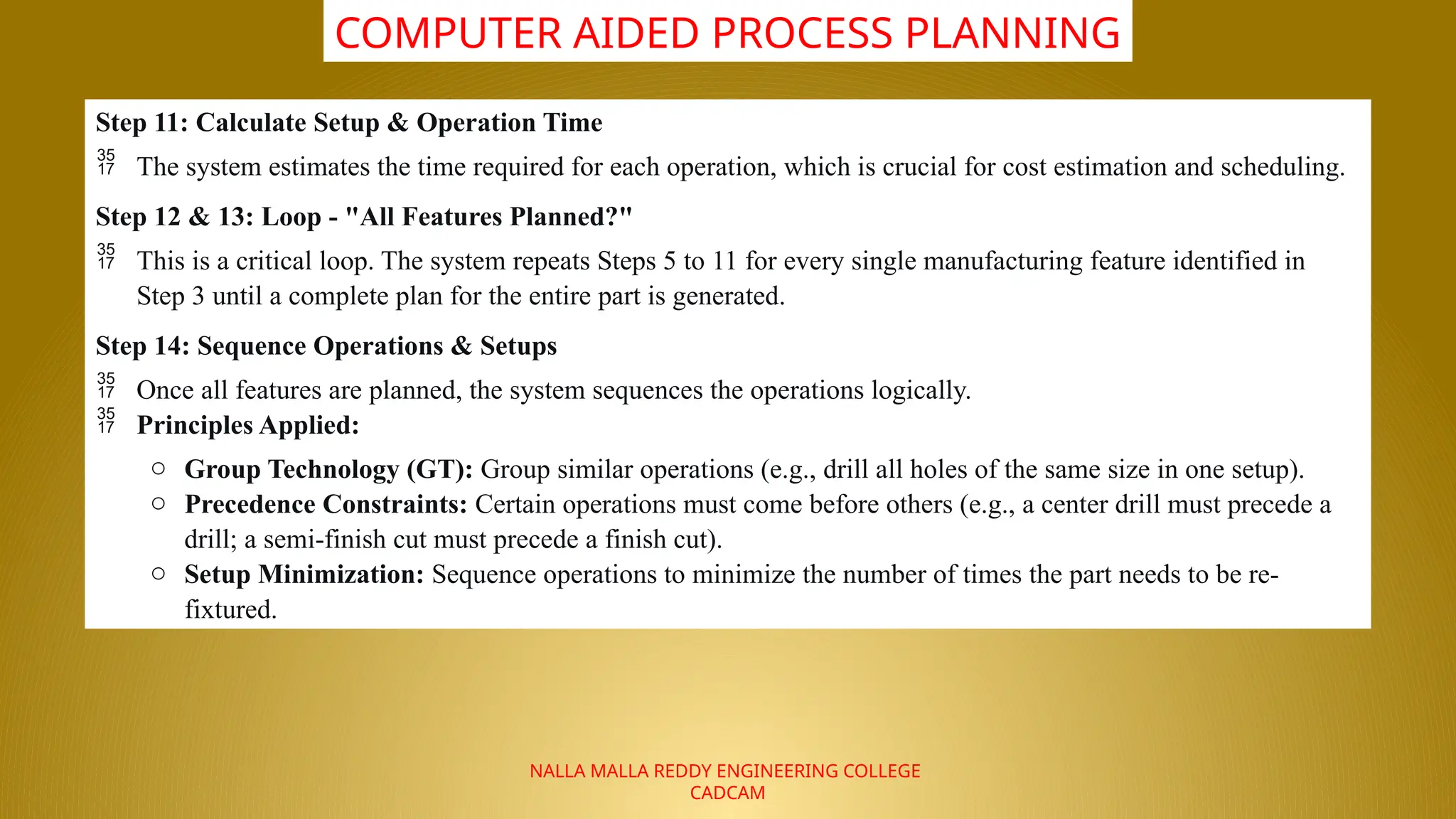
Step 11: Calculate Setup & Operation Time
The system estimates the time required for each operation, which is crucial for cost estimation and scheduling.
Step 12 & 13: Loop - "All Features Planned?"
This is a critical loop. The system repeats Steps 5 to 11 for every single manufacturing feature identified in
Step 3 until a complete plan for the entire part is generated.
Step 14: Sequence Operations & Setups
Once all features are planned, the system sequences the operations logically.
Principles Applied:
o Group Technology (GT): Group similar operations (e.g., drill all holes of the same size in one setup).
o Precedence Constraints: Certain operations must come before others (e.g., a center drill must precede a
drill; a semi-finish cut must precede a finish cut).
o Setup Minimization: Sequence operations to minimize the number of times the part needs to be re-
fixtured.
24.
NALLA MALLA REDDYENGINEERING COLLEGE
CADCAM
COMPUTER AIDED PROCESS PLANNING
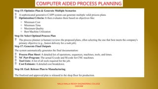
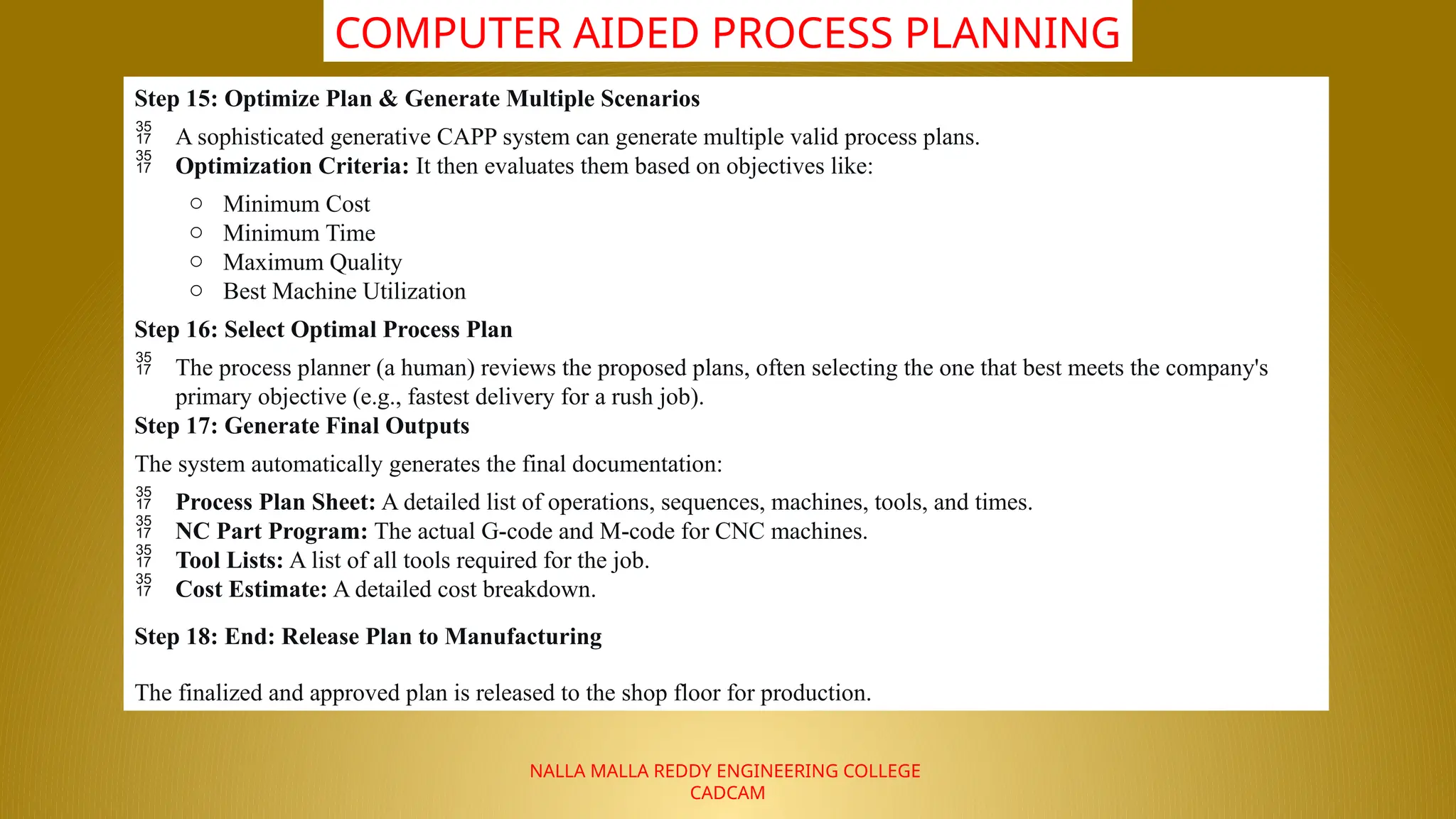
Step 15: Optimize Plan & Generate Multiple Scenarios
A sophisticated generative CAPP system can generate multiple valid process plans.
Optimization Criteria: It then evaluates them based on objectives like:
o Minimum Cost
o Minimum Time
o Maximum Quality
o Best Machine Utilization
Step 16: Select Optimal Process Plan
The process planner (a human) reviews the proposed plans, often selecting the one that best meets the company's
primary objective (e.g., fastest delivery for a rush job).
Step 17: Generate Final Outputs
The system automatically generates the final documentation:
Process Plan Sheet: A detailed list of operations, sequences, machines, tools, and times.
NC Part Program: The actual G-code and M-code for CNC machines.
Tool Lists: A list of all tools required for the job.
Cost Estimate: A detailed cost breakdown.
Step 18: End: Release Plan to Manufacturing
The finalized and approved plan is released to the shop floor for production.
25.
NALLA MALLA REDDYENGINEERING COLLEGE
CADCAM
COMPUTER AIDED PROCESS PLANNING
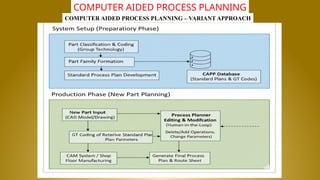
COMPUTER AIDED PROCESS PLANNING – VARIANT APPROACH
26.
NALLA MALLA REDDYENGINEERING COLLEGE
CADCAM
COMPUTER AIDED PROCESS PLANNING
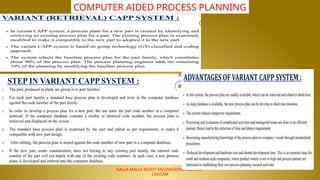
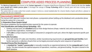
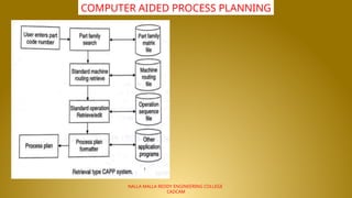
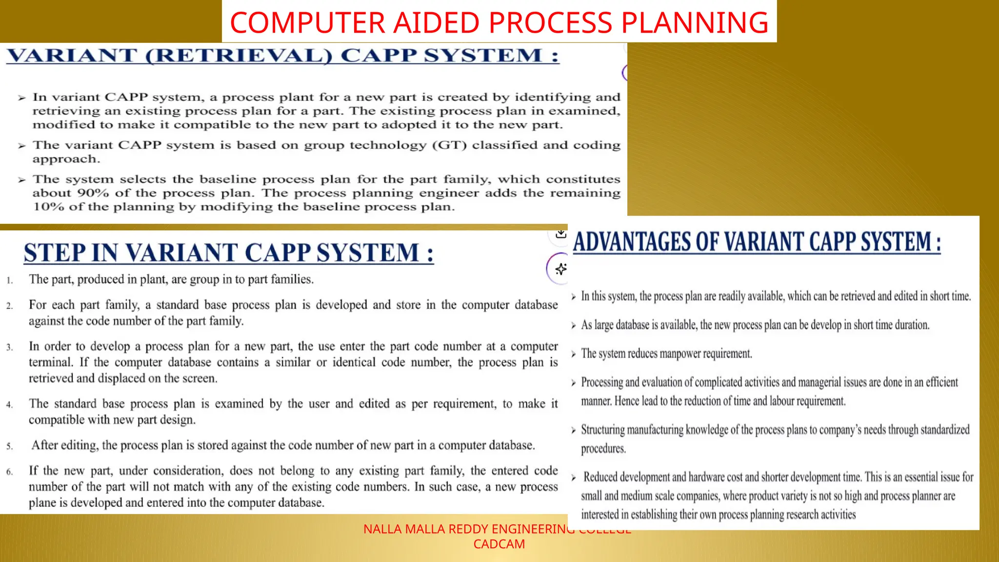
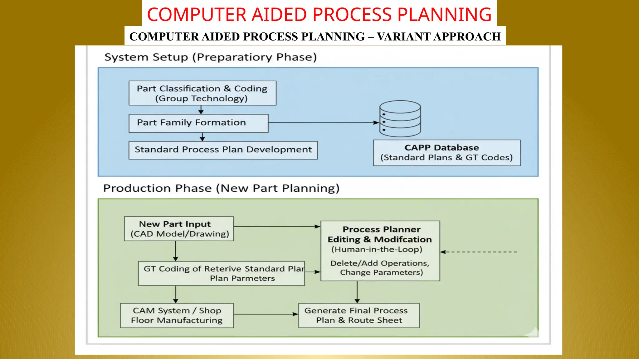
The Retrieval Approach (also known as the Variant Approach) to Computer-Aided Process Planning (CAPP) is based on the idea that similar
parts should have similar process plans. It leverages the concept of Group Technology (GT) to classify parts and reuse existing, proven
manufacturing plans.
The system does not create a plan from scratch; instead, it retrieves a stored standard plan for a known family of parts and allows a planner to
modify it for the new component.
Steps Involved in VARIANT CAPP
The Variant CAPP approach involves two main phases: a preparatory phase (setting up the database) and a production phase
(using the system for a new part).
1. Preparatory Phase (System Setup)
This phase establishes the foundational data required for the system to operate:
•Part Classification and Coding (Group Technology - GT):
• Existing and new parts are classified based on their design features (shape, material, size) and manufacturing
characteristics (operations, machine type).
• A GT code (a unique sequence of digits or characters) is assigned to each part, where the digits represent specific part
attributes.
•Part Family Formation:
• Parts with similar GT codes and, therefore, similar manufacturing requirements are grouped into part families. Each
family represents a collection of parts that can be largely processed using the same sequence of operations.
•Standard Process Plan Development:
• A standard (or "master") process plan is manually created by an experienced planner for the composite part of each
family. This plan includes the optimal sequence of operations, machines, and general tooling. This plan is stored in the
CAPP database.
27.
NALLA MALLA REDDYENGINEERING COLLEGE
CADCAM
COMPUTER AIDED PROCESS PLANNING
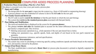
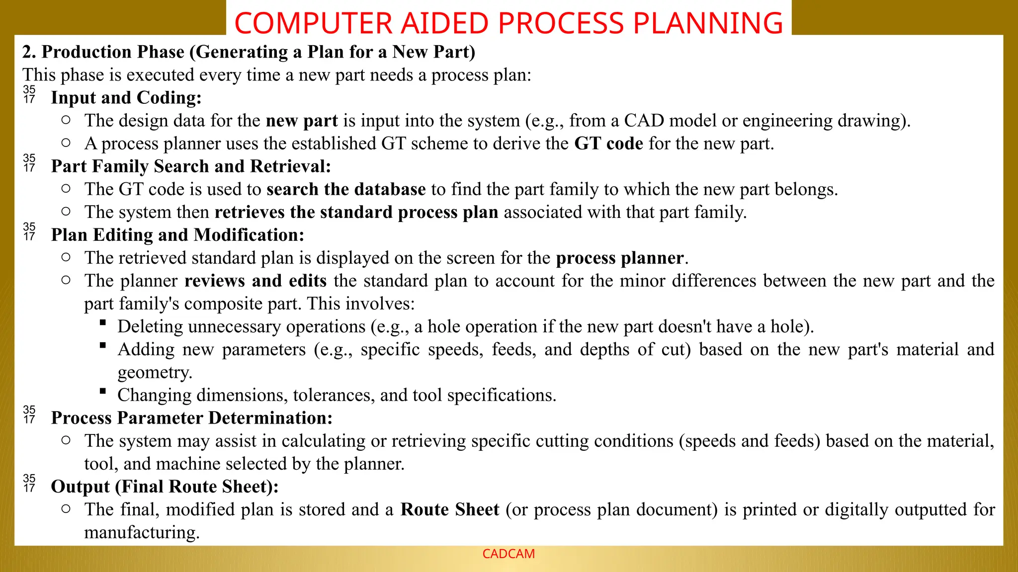
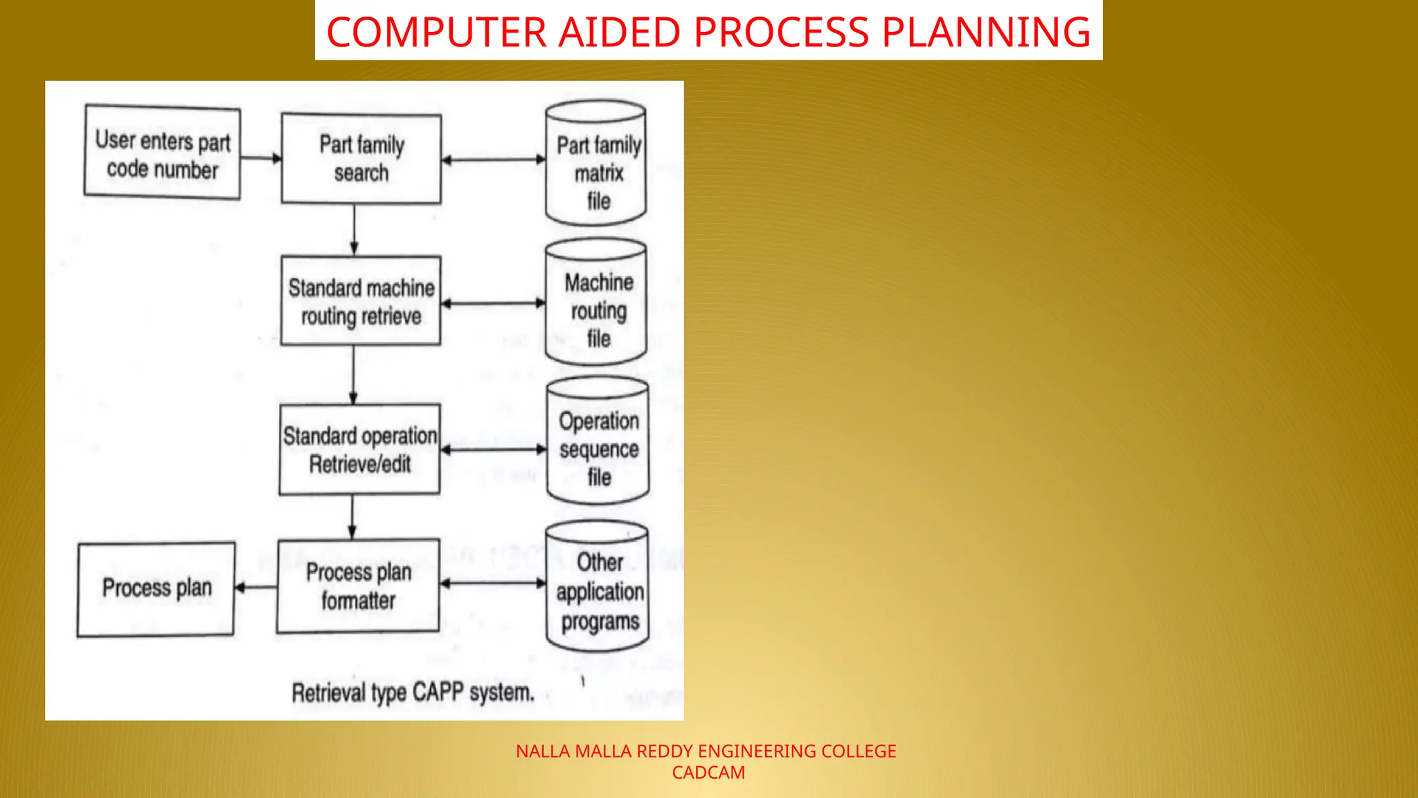
2. Production Phase (Generating a Plan for a New Part)
This phase is executed every time a new part needs a process plan:
Input and Coding:
o The design data for the new part is input into the system (e.g., from a CAD model or engineering drawing).
o A process planner uses the established GT scheme to derive the GT code for the new part.
Part Family Search and Retrieval:
o The GT code is used to search the database to find the part family to which the new part belongs.
o The system then retrieves the standard process plan associated with that part family.
Plan Editing and Modification:
o The retrieved standard plan is displayed on the screen for the process planner.
o The planner reviews and edits the standard plan to account for the minor differences between the new part and the
part family's composite part. This involves:
Deleting unnecessary operations (e.g., a hole operation if the new part doesn't have a hole).
Adding new parameters (e.g., specific speeds, feeds, and depths of cut) based on the new part's material and
geometry.
Changing dimensions, tolerances, and tool specifications.
Process Parameter Determination:
o The system may assist in calculating or retrieving specific cutting conditions (speeds and feeds) based on the material,
tool, and machine selected by the planner.
Output (Final Route Sheet):
o The final, modified plan is stored and a Route Sheet (or process plan document) is printed or digitally outputted for
manufacturing.
28.
NALLA MALLA REDDYENGINEERING COLLEGE
CADCAM
COMPUTER AIDED PROCESS PLANNING
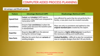
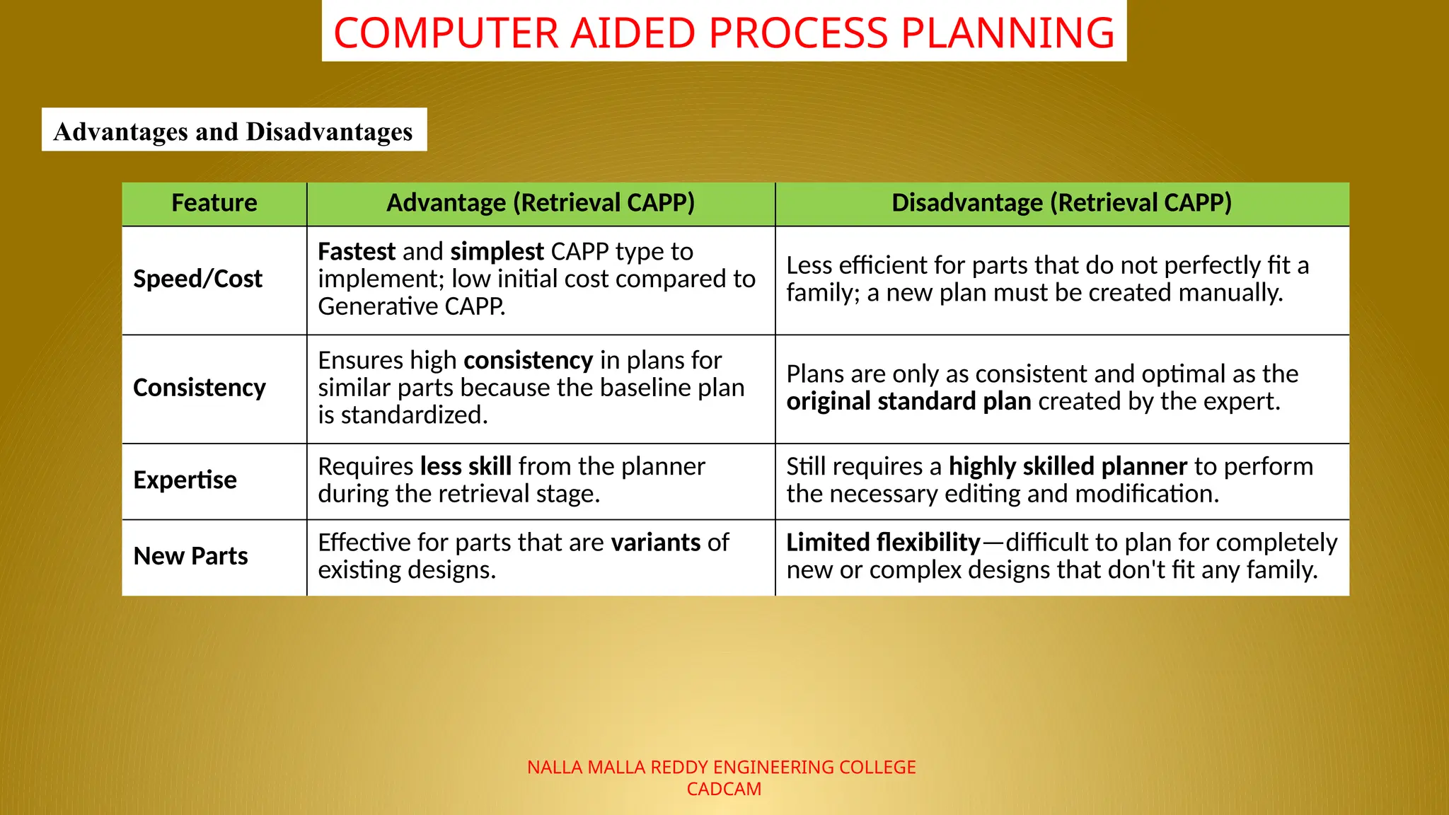
Feature Advantage (Retrieval CAPP) Disadvantage (Retrieval CAPP)
Speed/Cost
Fastest and simplest CAPP type to
implement; low initial cost compared to
Generative CAPP.
Less efficient for parts that do not perfectly fit a
family; a new plan must be created manually.
Consistency
Ensures high consistency in plans for
similar parts because the baseline plan
is standardized.
Plans are only as consistent and optimal as the
original standard plan created by the expert.
Expertise
Requires less skill from the planner
during the retrieval stage.
Still requires a highly skilled planner to perform
the necessary editing and modification.
New Parts
Effective for parts that are variants of
existing designs.
Limited flexibility—difficult to plan for completely
new or complex designs that don't fit any family.
Advantages and Disadvantages
29.
NALLA MALLA REDDYENGINEERING COLLEGE
CADCAM
COMPUTER AIDED PROCESS PLANNING
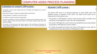
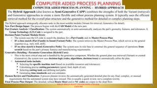
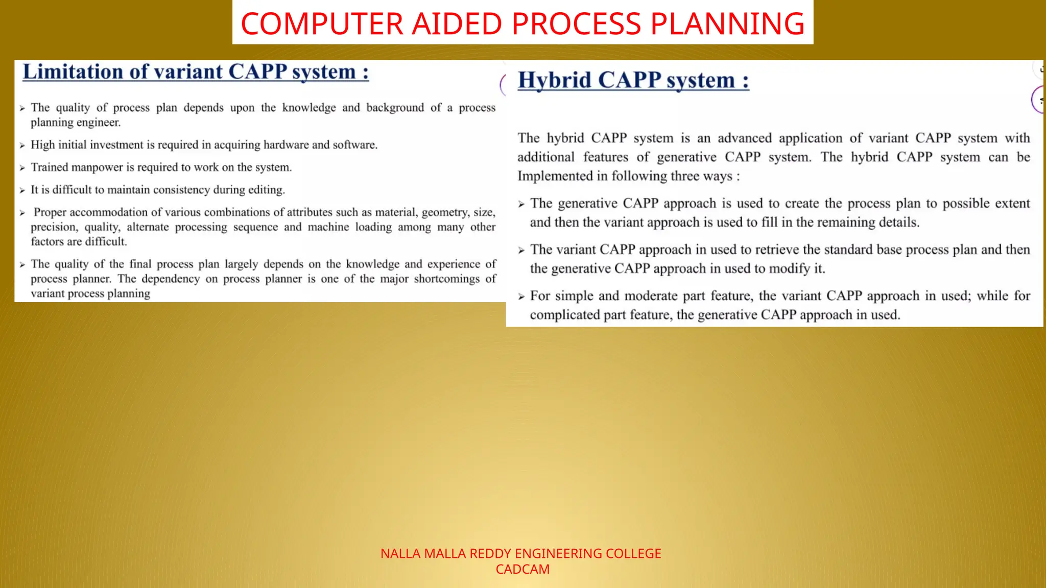
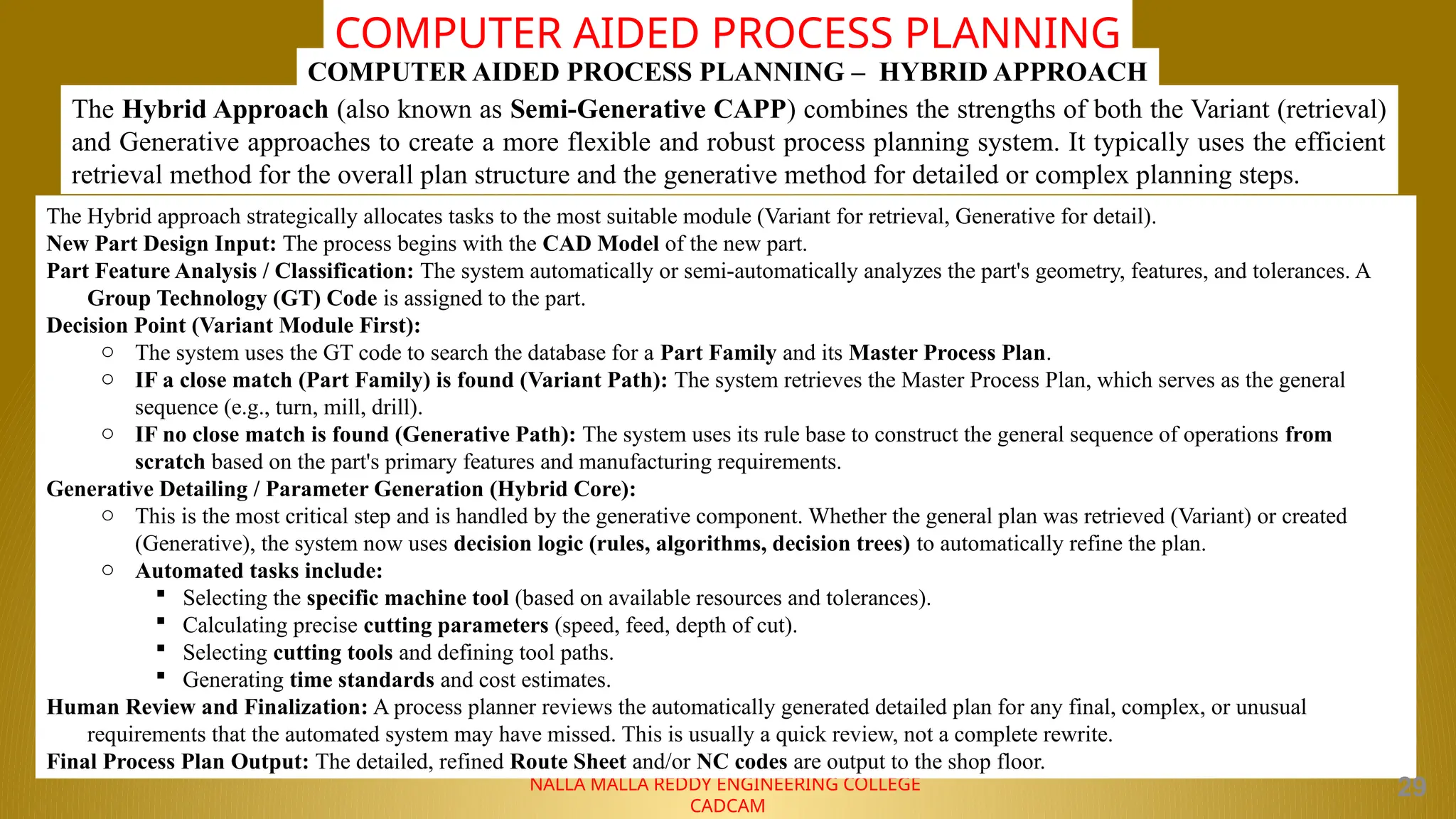
The Hybrid Approach (also known as Semi-Generative CAPP) combines the strengths of both the Variant (retrieval)
and Generative approaches to create a more flexible and robust process planning system. It typically uses the efficient
retrieval method for the overall plan structure and the generative method for detailed or complex planning steps.
COMPUTER AIDED PROCESS PLANNING – HYBRID APPROACH
The Hybrid approach strategically allocates tasks to the most suitable module (Variant for retrieval, Generative for detail).
New Part Design Input: The process begins with the CAD Model of the new part.
Part Feature Analysis / Classification: The system automatically or semi-automatically analyzes the part's geometry, features, and tolerances. A
Group Technology (GT) Code is assigned to the part.
Decision Point (Variant Module First):
o The system uses the GT code to search the database for a Part Family and its Master Process Plan.
o IF a close match (Part Family) is found (Variant Path): The system retrieves the Master Process Plan, which serves as the general
sequence (e.g., turn, mill, drill).
o IF no close match is found (Generative Path): The system uses its rule base to construct the general sequence of operations from
scratch based on the part's primary features and manufacturing requirements.
Generative Detailing / Parameter Generation (Hybrid Core):
o This is the most critical step and is handled by the generative component. Whether the general plan was retrieved (Variant) or created
(Generative), the system now uses decision logic (rules, algorithms, decision trees) to automatically refine the plan.
o Automated tasks include:
Selecting the specific machine tool (based on available resources and tolerances).
Calculating precise cutting parameters (speed, feed, depth of cut).
Selecting cutting tools and defining tool paths.
Generating time standards and cost estimates.
Human Review and Finalization: A process planner reviews the automatically generated detailed plan for any final, complex, or unusual
requirements that the automated system may have missed. This is usually a quick review, not a complete rewrite.
Final Process Plan Output: The detailed, refined Route Sheet and/or NC codes are output to the shop floor.
29
30.
NALLA MALLA REDDYENGINEERING COLLEGE
CADCAM
COMPUTER AIDED PROCESS PLANNING
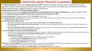
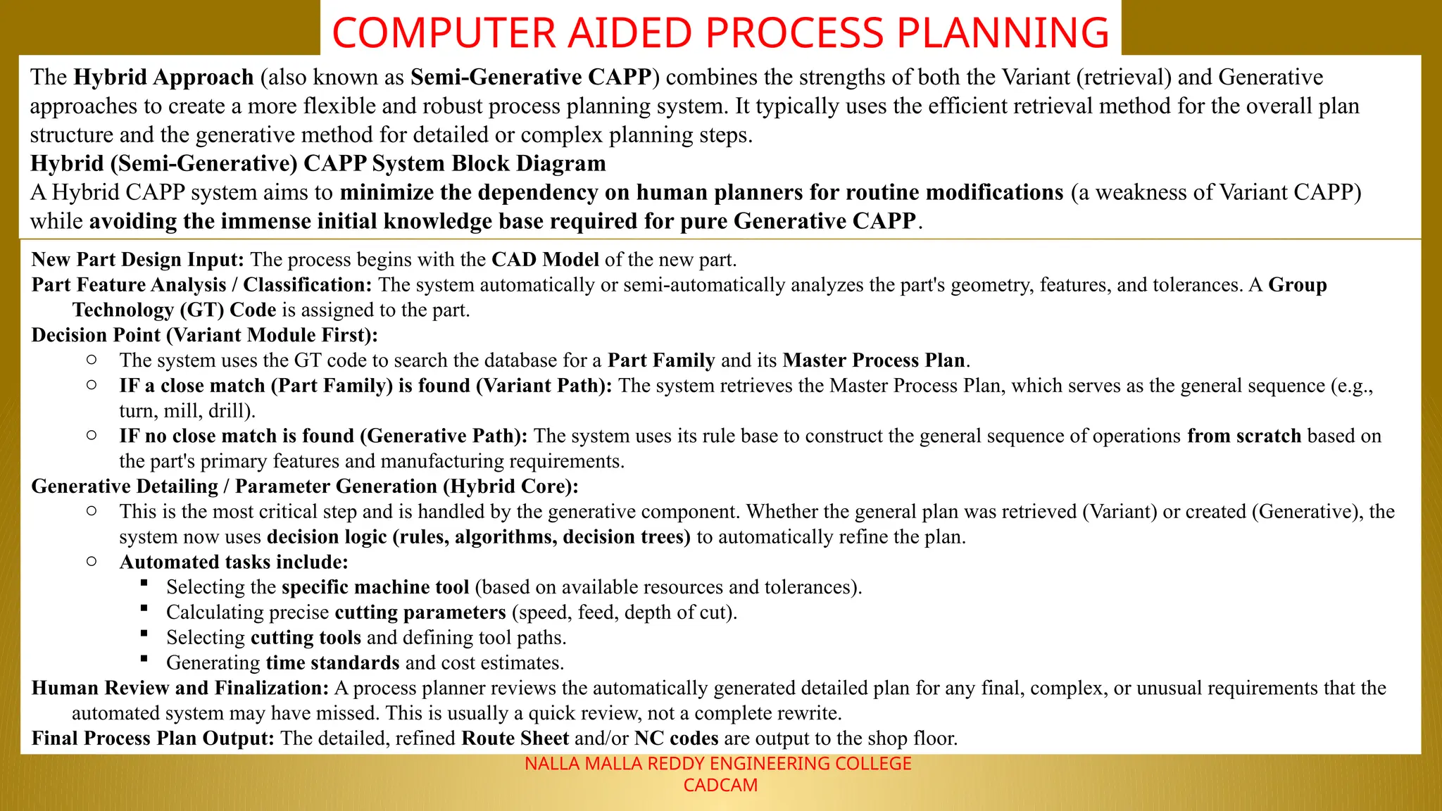
The Hybrid Approach (also known as Semi-Generative CAPP) combines the strengths of both the Variant (retrieval) and Generative
approaches to create a more flexible and robust process planning system. It typically uses the efficient retrieval method for the overall plan
structure and the generative method for detailed or complex planning steps.
Hybrid (Semi-Generative) CAPP System Block Diagram
A Hybrid CAPP system aims to minimize the dependency on human planners for routine modifications (a weakness of Variant CAPP)
while avoiding the immense initial knowledge base required for pure Generative CAPP.
New Part Design Input: The process begins with the CAD Model of the new part.
Part Feature Analysis / Classification: The system automatically or semi-automatically analyzes the part's geometry, features, and tolerances. A Group
Technology (GT) Code is assigned to the part.
Decision Point (Variant Module First):
o The system uses the GT code to search the database for a Part Family and its Master Process Plan.
o IF a close match (Part Family) is found (Variant Path): The system retrieves the Master Process Plan, which serves as the general sequence (e.g.,
turn, mill, drill).
o IF no close match is found (Generative Path): The system uses its rule base to construct the general sequence of operations from scratch based on
the part's primary features and manufacturing requirements.
Generative Detailing / Parameter Generation (Hybrid Core):
o This is the most critical step and is handled by the generative component. Whether the general plan was retrieved (Variant) or created (Generative), the
system now uses decision logic (rules, algorithms, decision trees) to automatically refine the plan.
o Automated tasks include:
Selecting the specific machine tool (based on available resources and tolerances).
Calculating precise cutting parameters (speed, feed, depth of cut).
Selecting cutting tools and defining tool paths.
Generating time standards and cost estimates.
Human Review and Finalization: A process planner reviews the automatically generated detailed plan for any final, complex, or unusual requirements that the
automated system may have missed. This is usually a quick review, not a complete rewrite.
Final Process Plan Output: The detailed, refined Route Sheet and/or NC codes are output to the shop floor.
31.
NALLA MALLA REDDYENGINEERING COLLEGE
CADCAM
COMPUTER AIDED PROCESS PLANNING
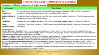
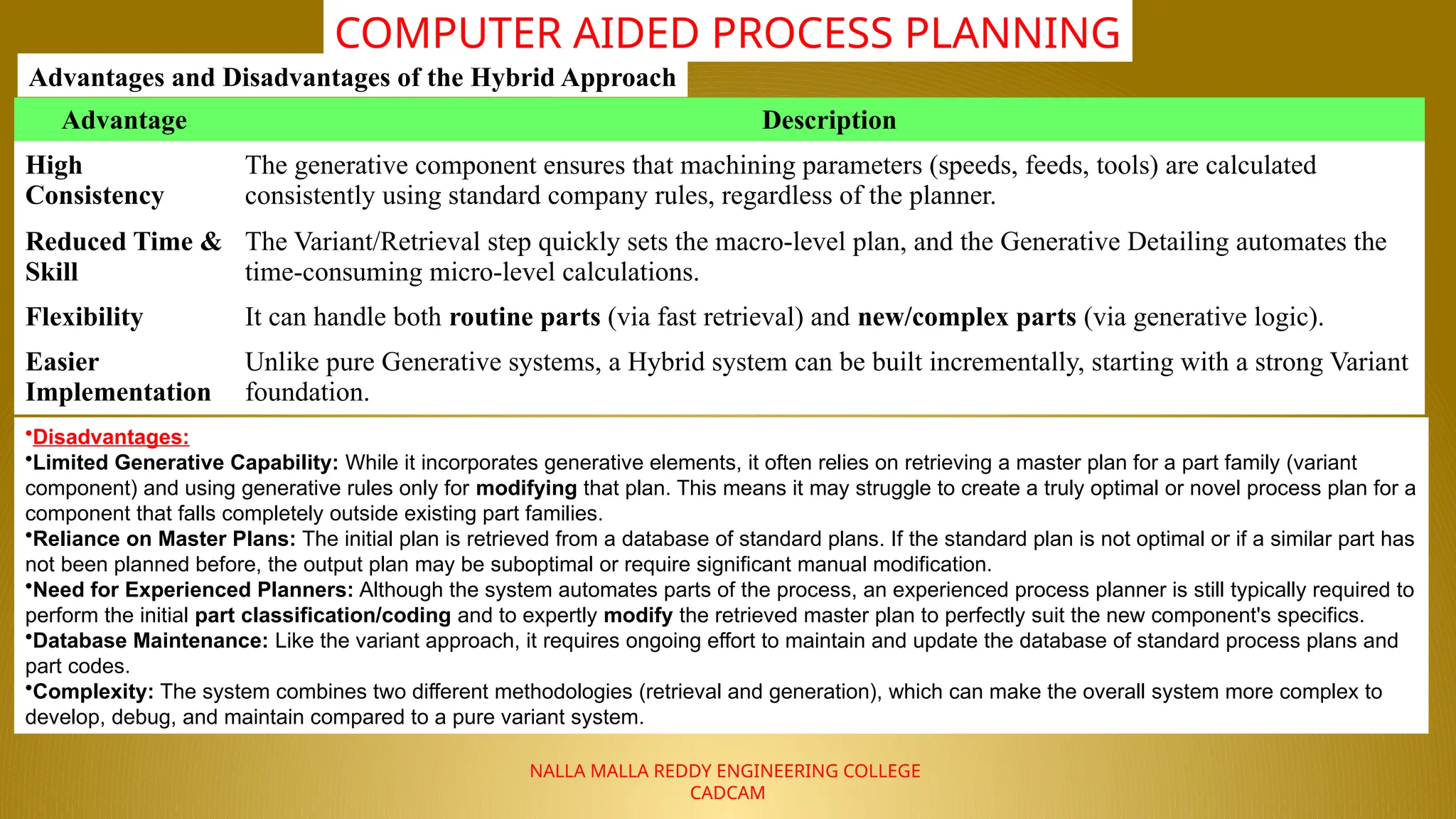
Advantages and Disadvantages of the Hybrid Approach
Advantage Description
High
Consistency
The generative component ensures that machining parameters (speeds, feeds, tools) are calculated
consistently using standard company rules, regardless of the planner.
Reduced Time &
Skill
The Variant/Retrieval step quickly sets the macro-level plan, and the Generative Detailing automates the
time-consuming micro-level calculations.
Flexibility It can handle both routine parts (via fast retrieval) and new/complex parts (via generative logic).
Easier
Implementation
Unlike pure Generative systems, a Hybrid system can be built incrementally, starting with a strong Variant
foundation.
•Disadvantages:
•Limited Generative Capability: While it incorporates generative elements, it often relies on retrieving a master plan for a part family (variant
component) and using generative rules only for modifying that plan. This means it may struggle to create a truly optimal or novel process plan for a
component that falls completely outside existing part families.
•Reliance on Master Plans: The initial plan is retrieved from a database of standard plans. If the standard plan is not optimal or if a similar part has
not been planned before, the output plan may be suboptimal or require significant manual modification.
•Need for Experienced Planners: Although the system automates parts of the process, an experienced process planner is still typically required to
perform the initial part classification/coding and to expertly modify the retrieved master plan to perfectly suit the new component's specifics.
•Database Maintenance: Like the variant approach, it requires ongoing effort to maintain and update the database of standard process plans and
part codes.
•Complexity: The system combines two different methodologies (retrieval and generation), which can make the overall system more complex to
develop, debug, and maintain compared to a pure variant system.
32.
NALLA MALLA REDDYENGINEERING COLLEGE
CADCAM
COMPUTER AIDED PROCESS PLANNING
33.
NALLA MALLA REDDYENGINEERING COLLEGE
CADCAM
COMPUTER AIDED PROCESS PLANNING
34.
NALLA MALLA REDDYENGINEERING COLLEGE
CADCAM
COMPUTER AIDED PROCESS PLANNING
35.
NALLA MALLA REDDYENGINEERING COLLEGE
CADCAM
COMPUTER AIDED PROCESS PLANNING
36.
NALLA MALLA REDDYENGINEERING COLLEGE
CADCAM
COMPUTER AIDED PROCESS PLANNING
37.
NALLA MALLA REDDYENGINEERING COLLEGE
CADCAM
COMPUTER AIDED PROCESS PLANNING
THANK YOU
Questions & Queries