Downloaded 37 times


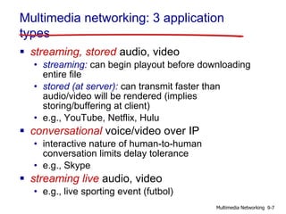


![Streaming multimedia: UDP
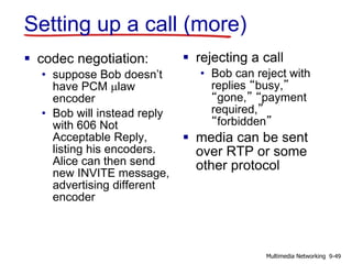
server sends at rate appropriate for client
• often: send rate = encoding rate = constant
rate
• transmission rate can be oblivious to
congestion levels
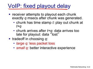
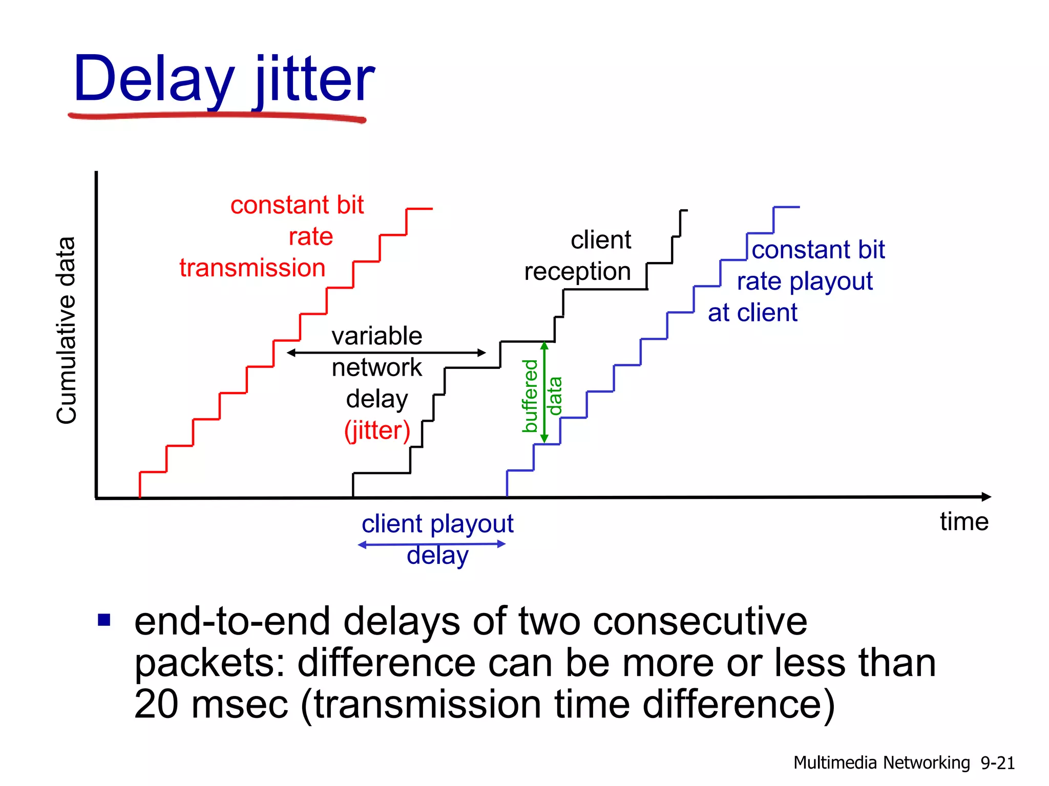
short playout delay (2-5 seconds) to remove
network jitter
error recovery: application-level, time
permitting
RTP [RFC 2326]: multimedia payload types
UDP may not go through firewalls
9-15Multimedia Networking](https://image.slidesharecdn.com/chapter9v701-200606183911/85/Chapter-9-Computer-Networking-a-top-down-Approach-7th-15-320.jpg)


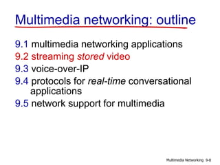
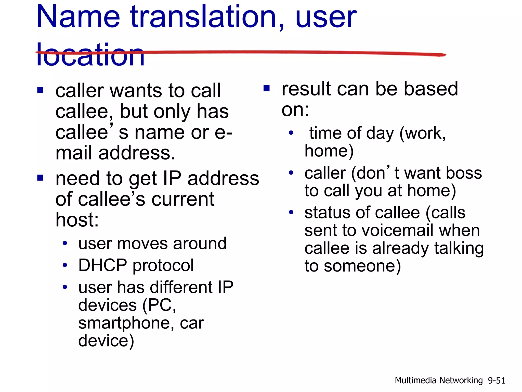
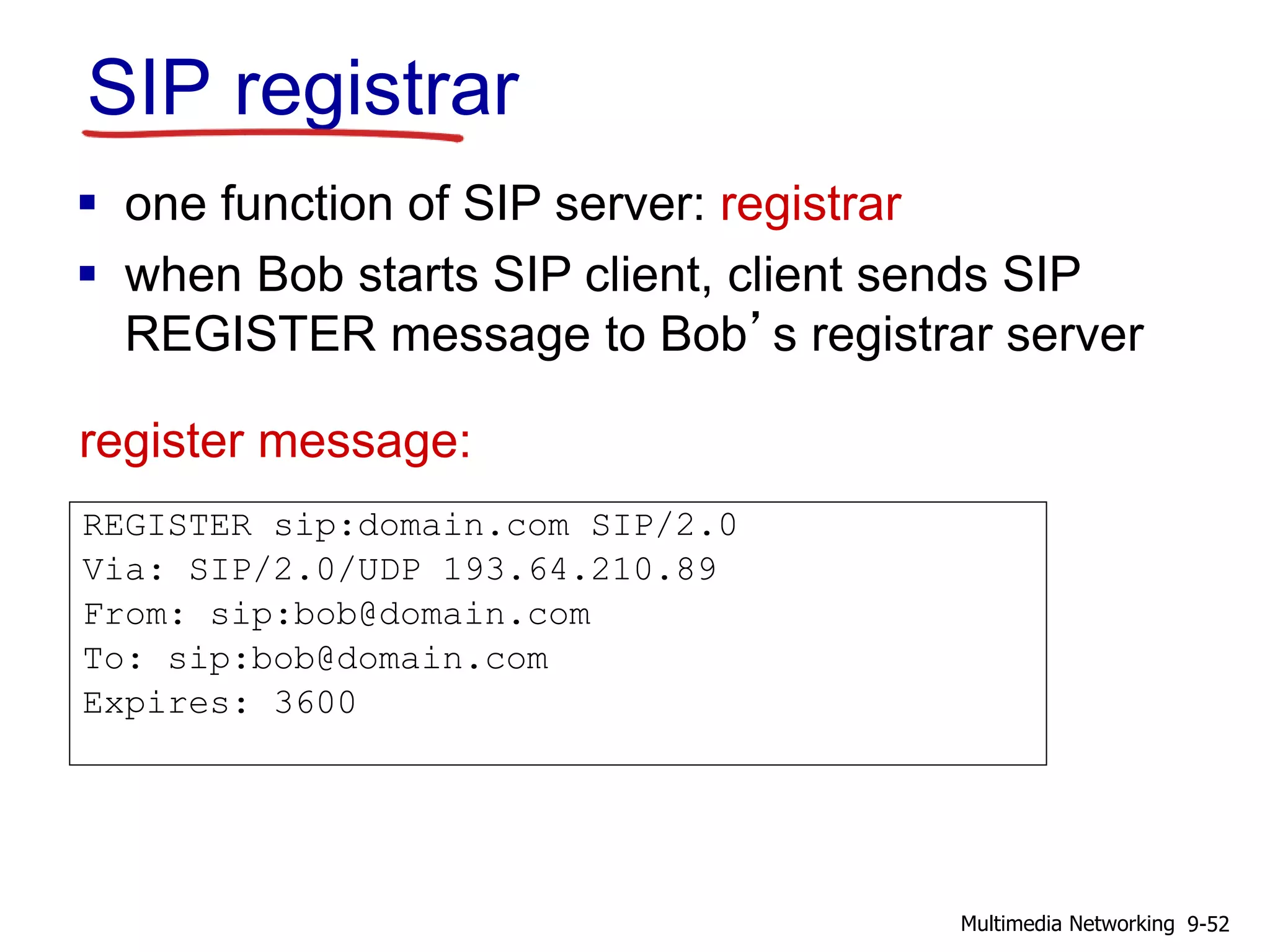
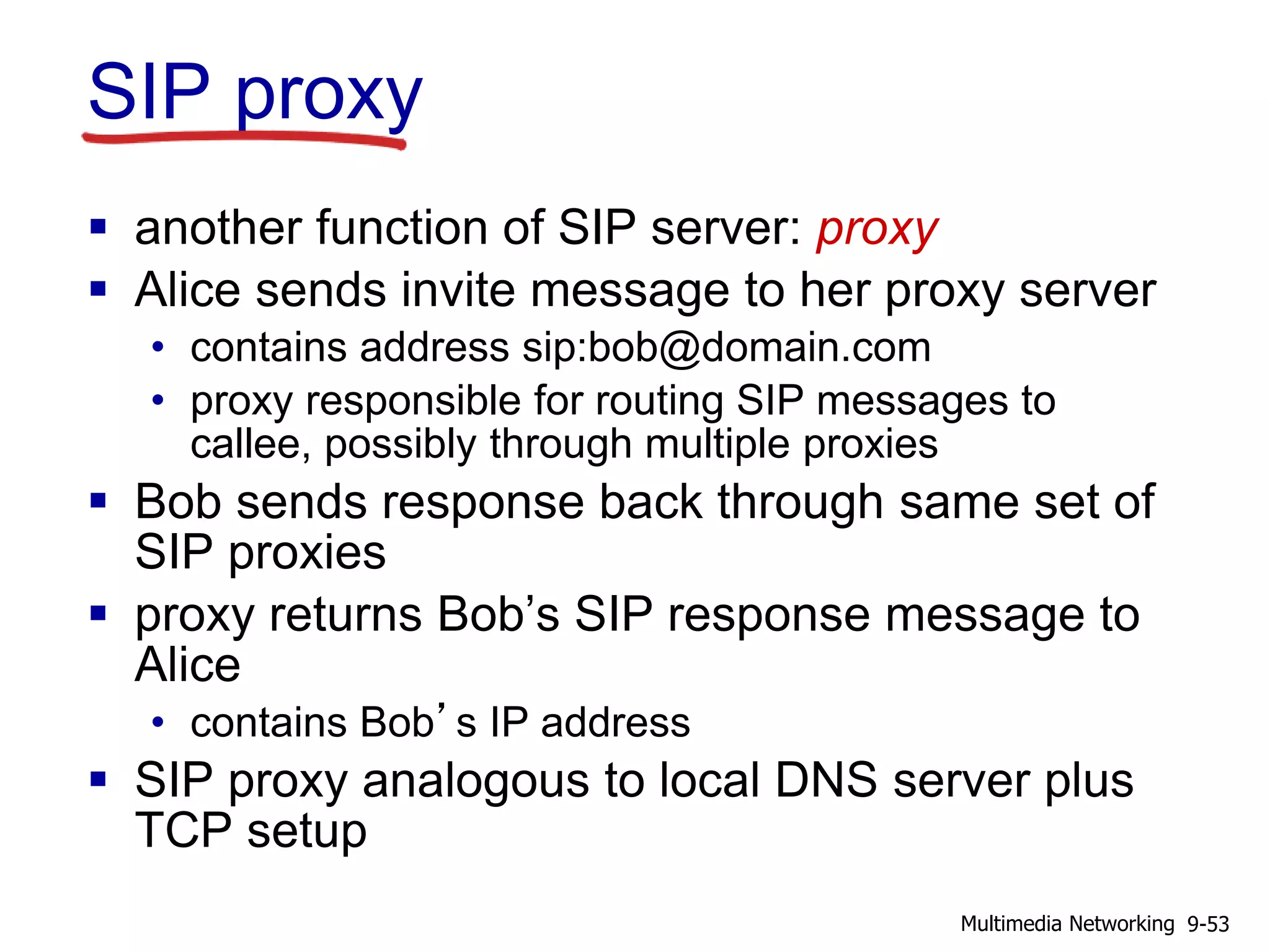
![SIP: Session Initiation Protocol [RFC
3261]
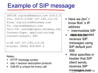
long-term vision:
all telephone calls, video conference calls
take place over Internet
people identified by names or e-mail
addresses, rather than by phone numbers
can reach callee (if callee so desires), no
matter where callee roams, no matter what IP
device callee is currently using
9-46Multimedia Networking](https://image.slidesharecdn.com/chapter9v701-200606183911/85/Chapter-9-Computer-Networking-a-top-down-Approach-7th-46-320.jpg)


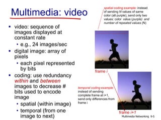
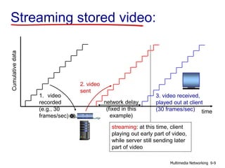
![Streaming multimedia: UDP
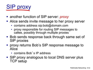
server sends at rate appropriate for client
• often: send rate = encoding rate = constant
rate
• transmission rate can be oblivious to
congestion levels
short playout delay (2-5 seconds) to remove
network jitter
error recovery: application-level, time
permitting
RTP [RFC 2326]: multimedia payload types
UDP may not go through firewalls
9-15Multimedia Networking](https://image.slidesharecdn.com/chapter9v701-200606183911/75/Chapter-9-Computer-Networking-a-top-down-Approach-7th-15-2048.jpg)


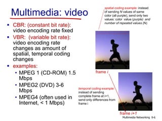
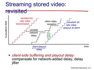
![SIP: Session Initiation Protocol [RFC
3261]
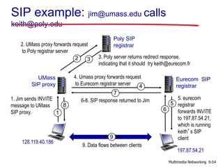
long-term vision:
all telephone calls, video conference calls
take place over Internet
people identified by names or e-mail
addresses, rather than by phone numbers
can reach callee (if callee so desires), no
matter where callee roams, no matter what IP
device callee is currently using
9-46Multimedia Networking](https://image.slidesharecdn.com/chapter9v701-200606183911/75/Chapter-9-Computer-Networking-a-top-down-Approach-7th-46-2048.jpg)


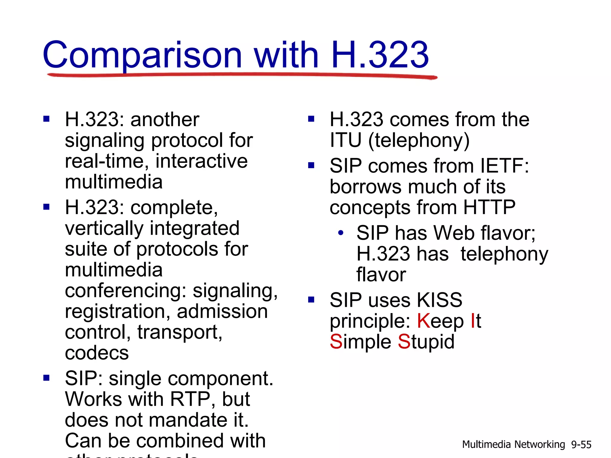


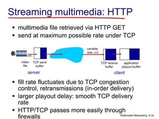
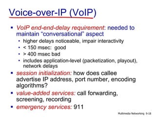
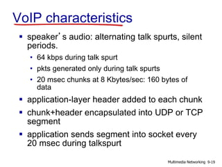
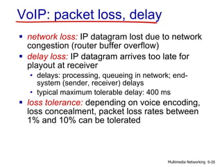
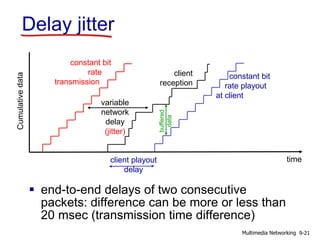
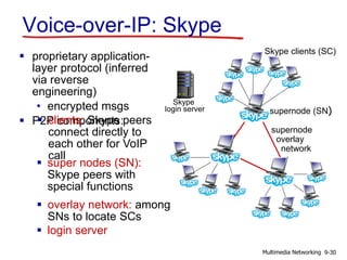
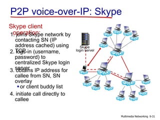
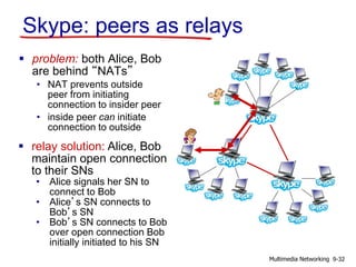
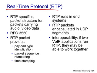
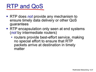
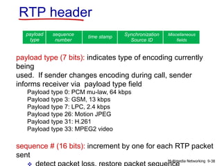
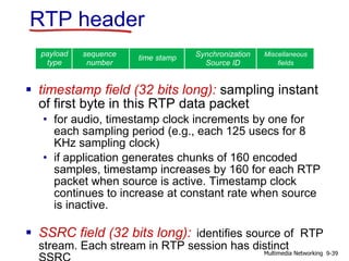
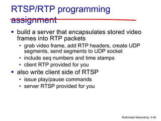
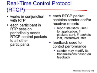
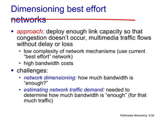
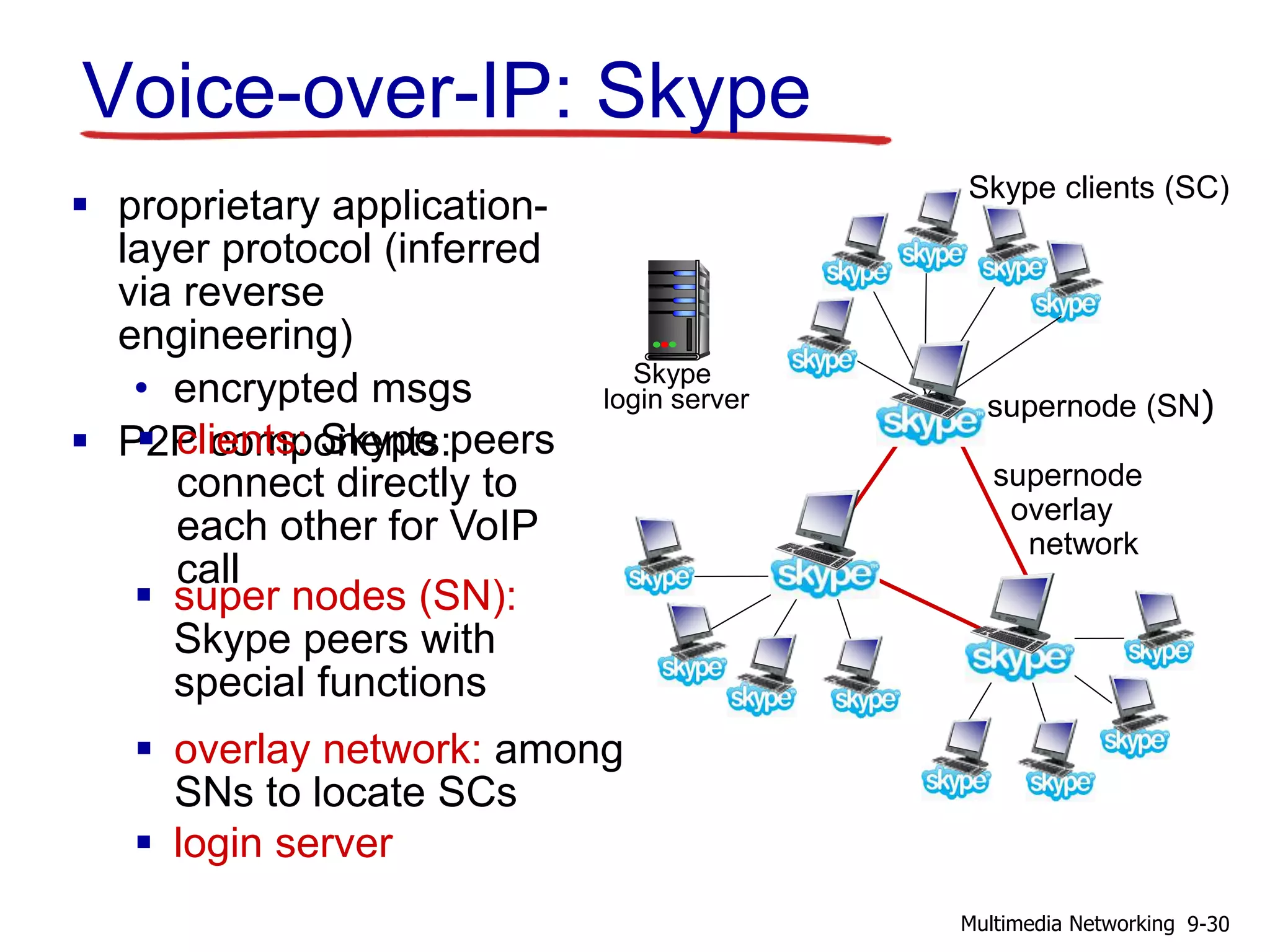
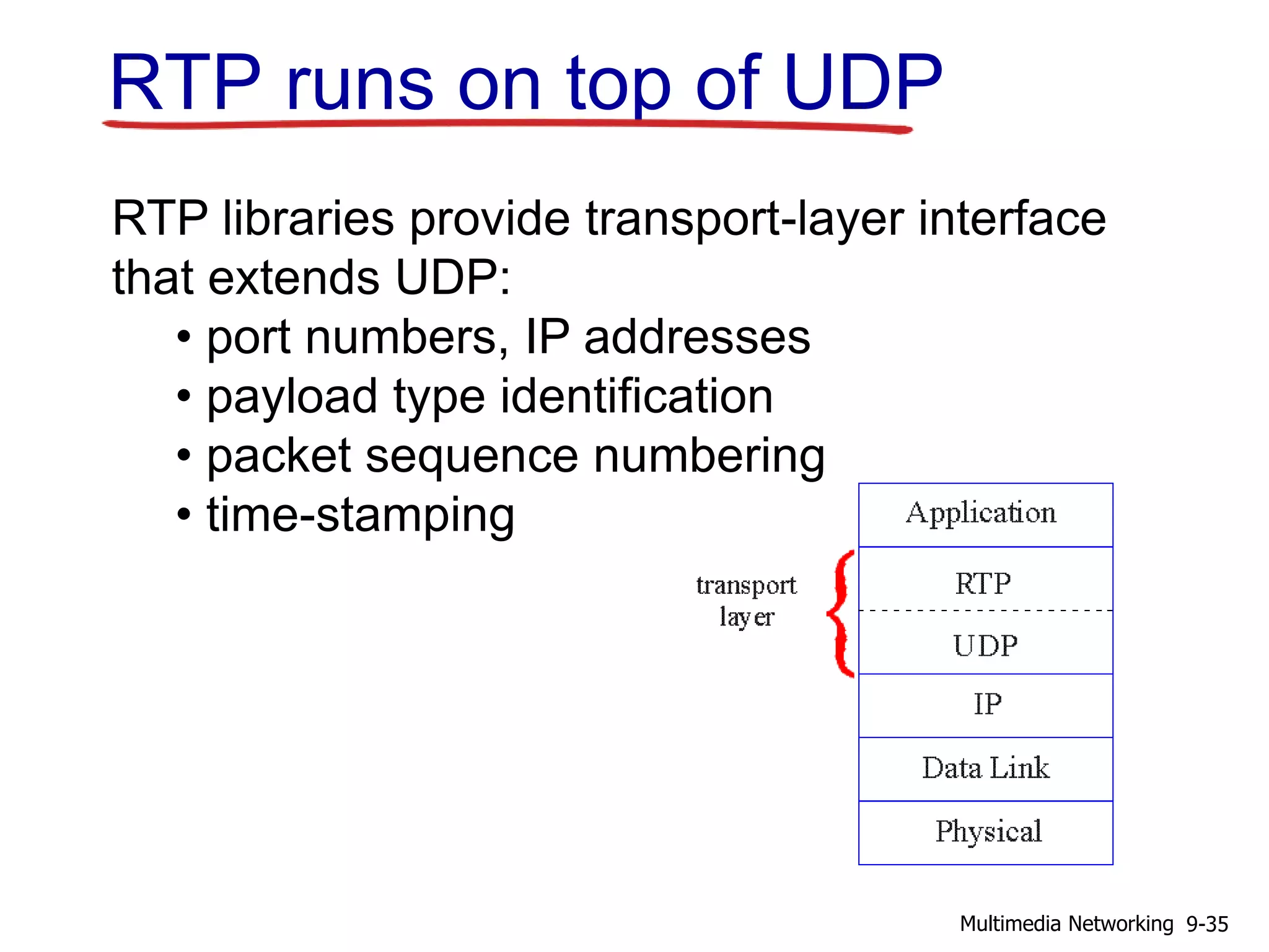
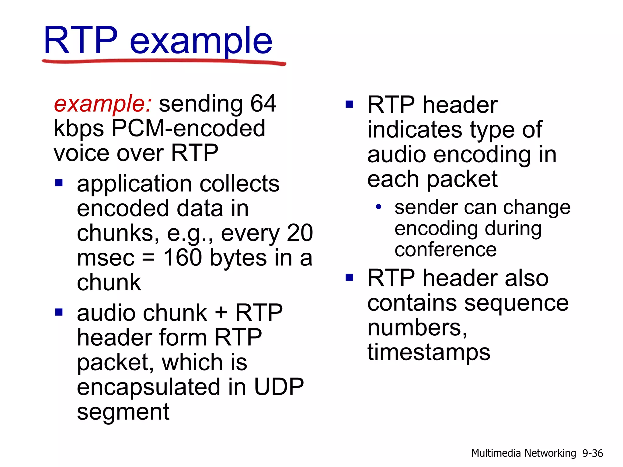
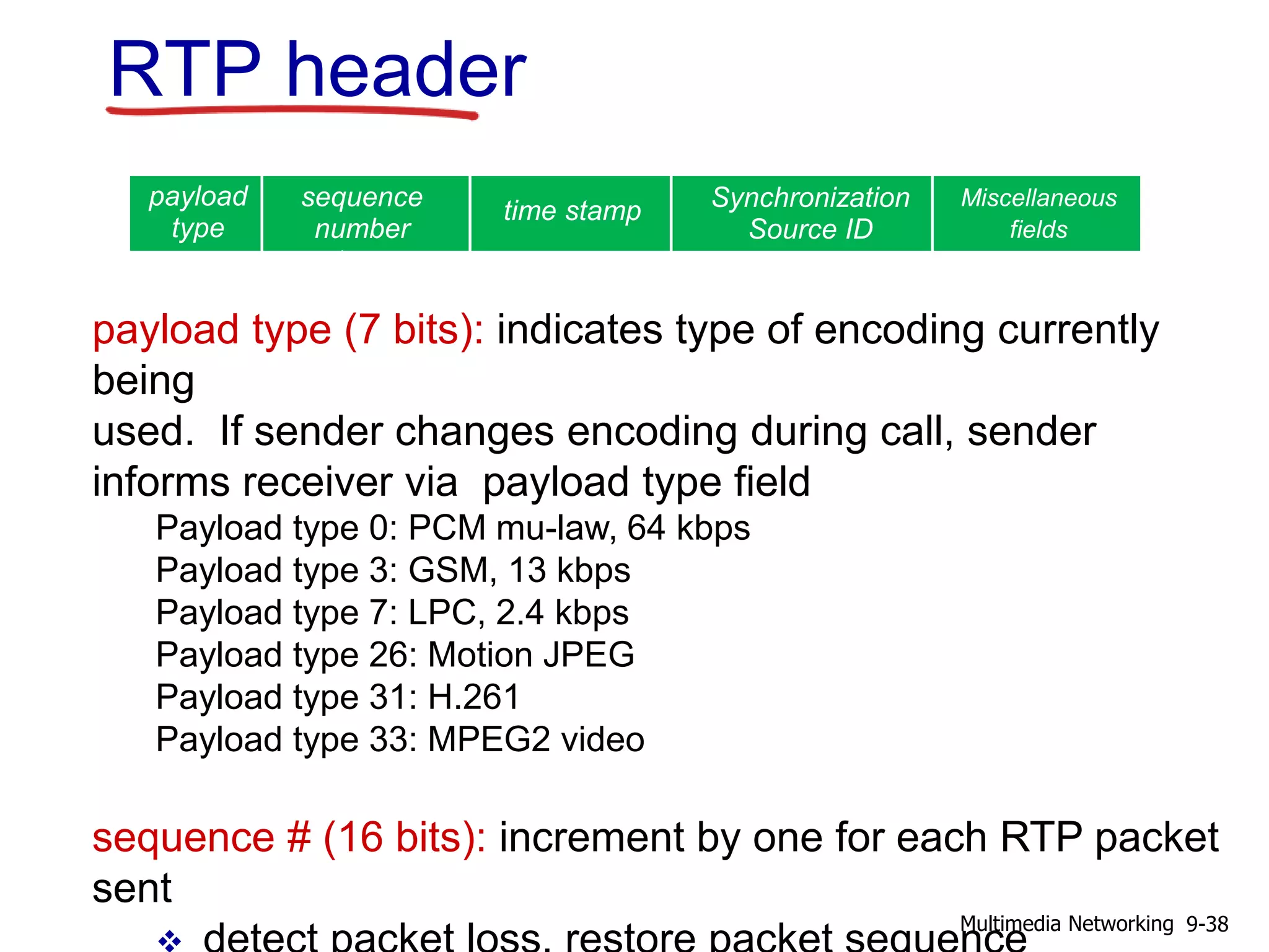
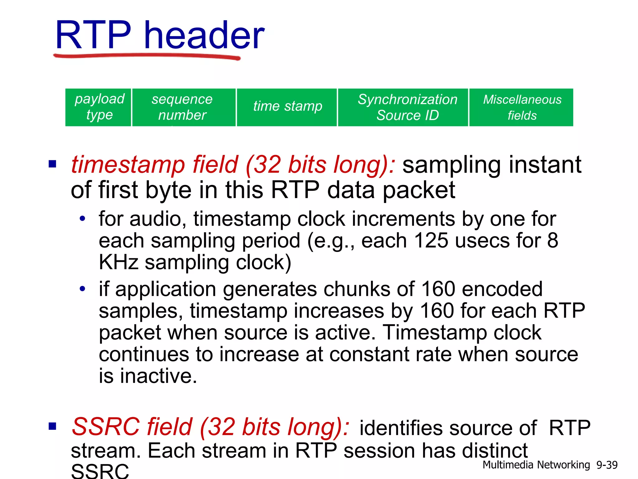
This document discusses protocols for real-time multimedia applications such as voice over IP. It introduces the Real-Time Protocol (RTP) which specifies packet structures for carrying audio and video data. RTP runs on top of UDP, providing functions like payload type identification, sequence numbering, and time stamping. It allows for interoperability between multimedia applications that both implement RTP. The document also discusses the Session Initiation Protocol (SIP) which is used to initialize multimedia sessions and exchange session description and control messages.


