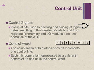
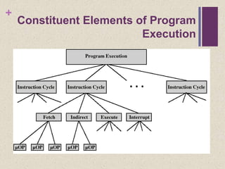
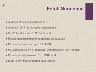
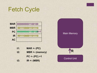
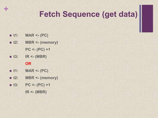
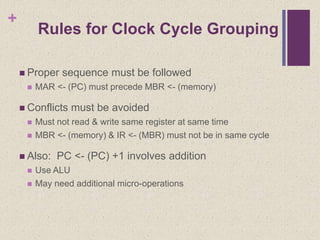
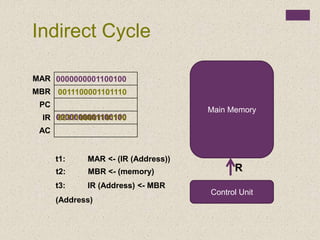
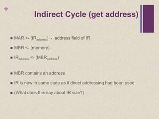
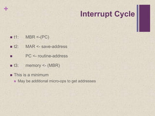
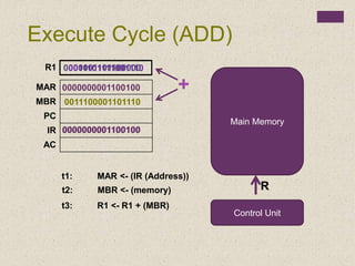
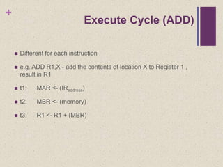
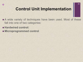
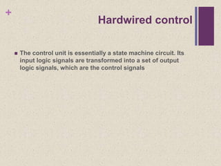
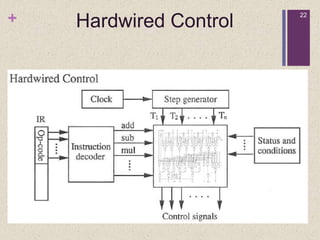
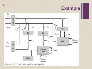
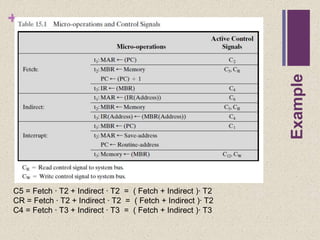
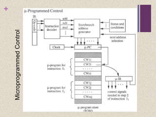
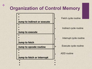
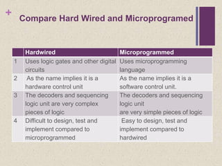
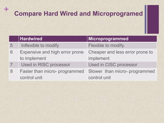
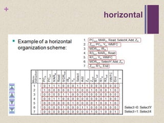
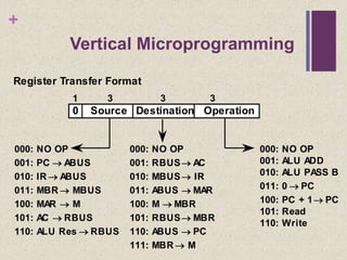
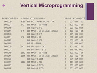
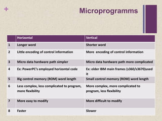
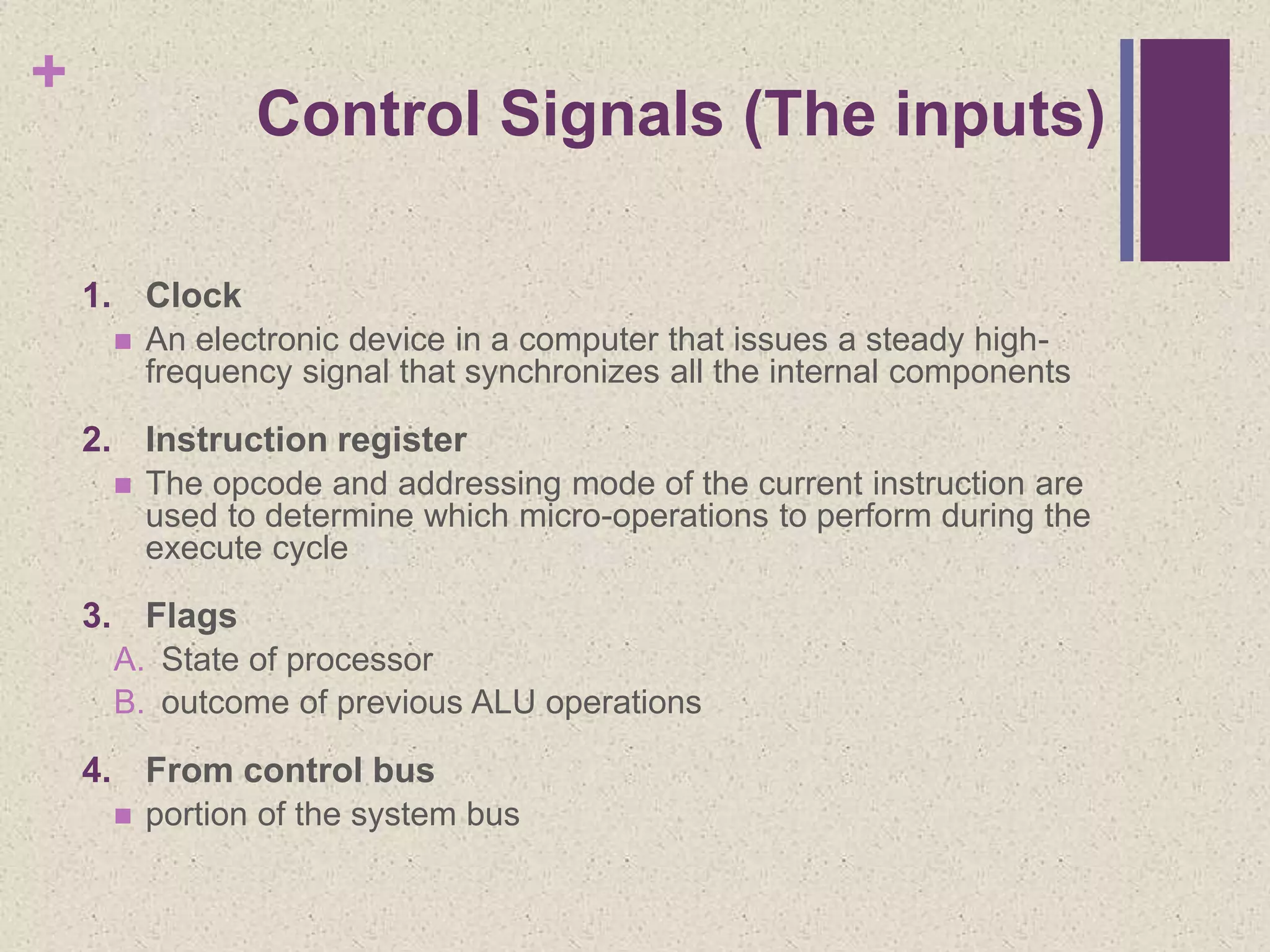
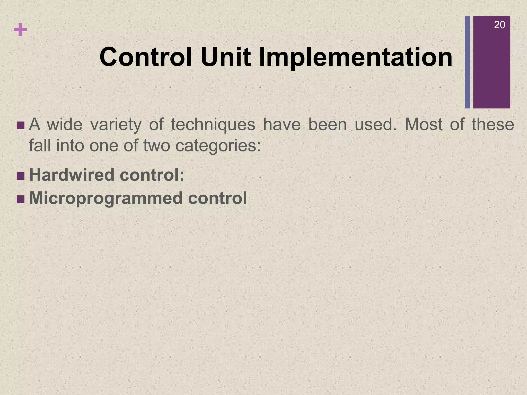
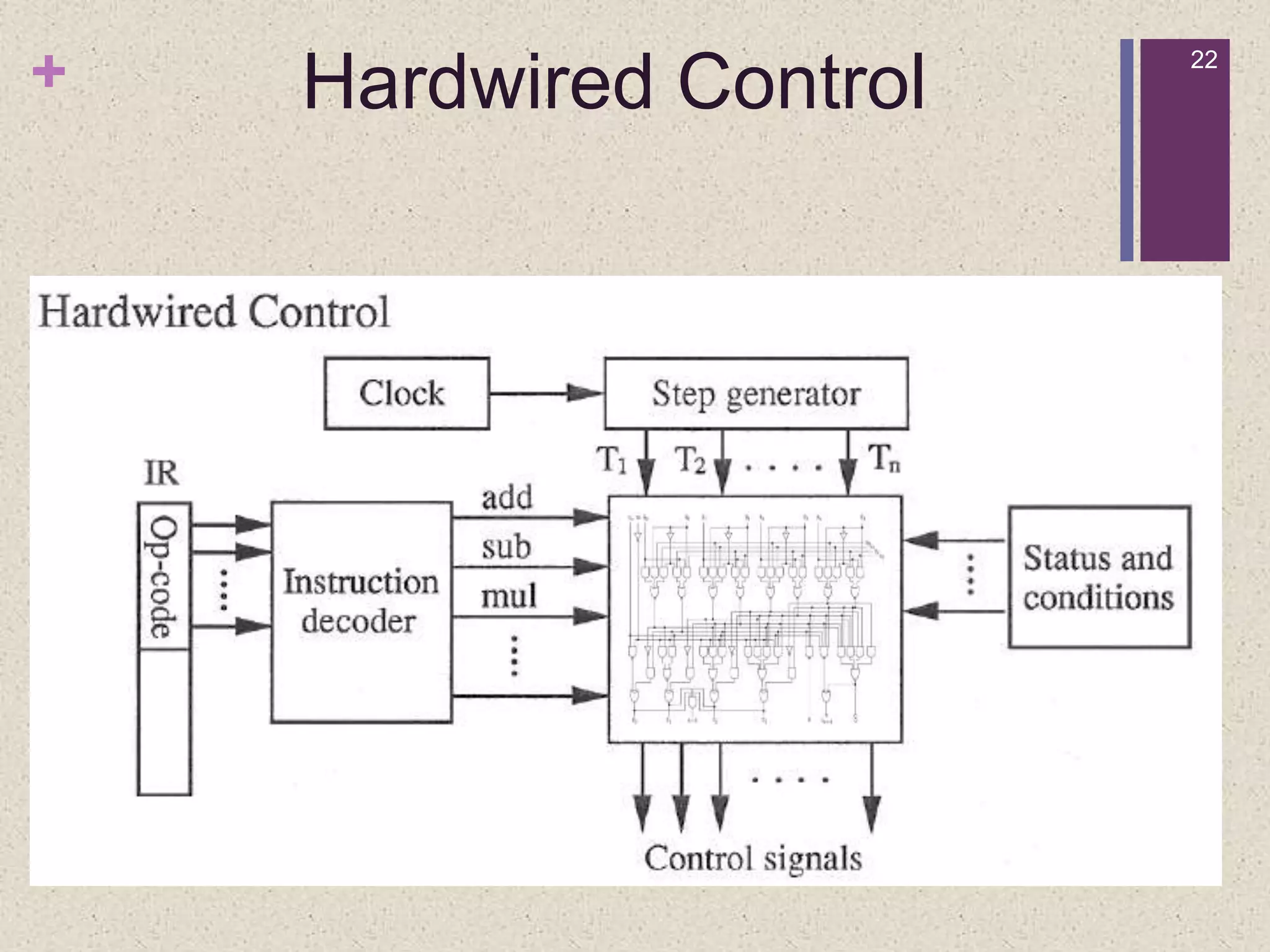
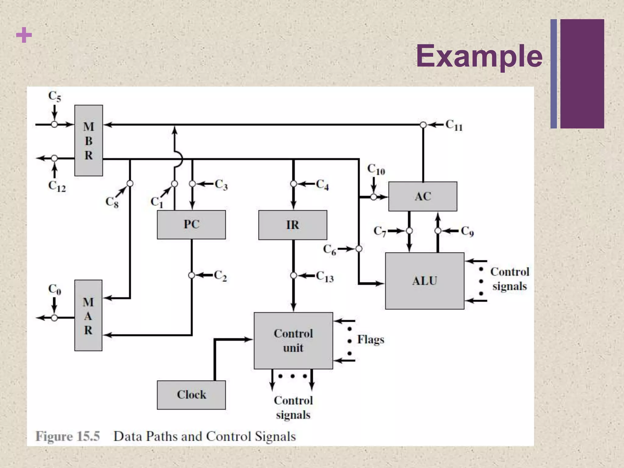
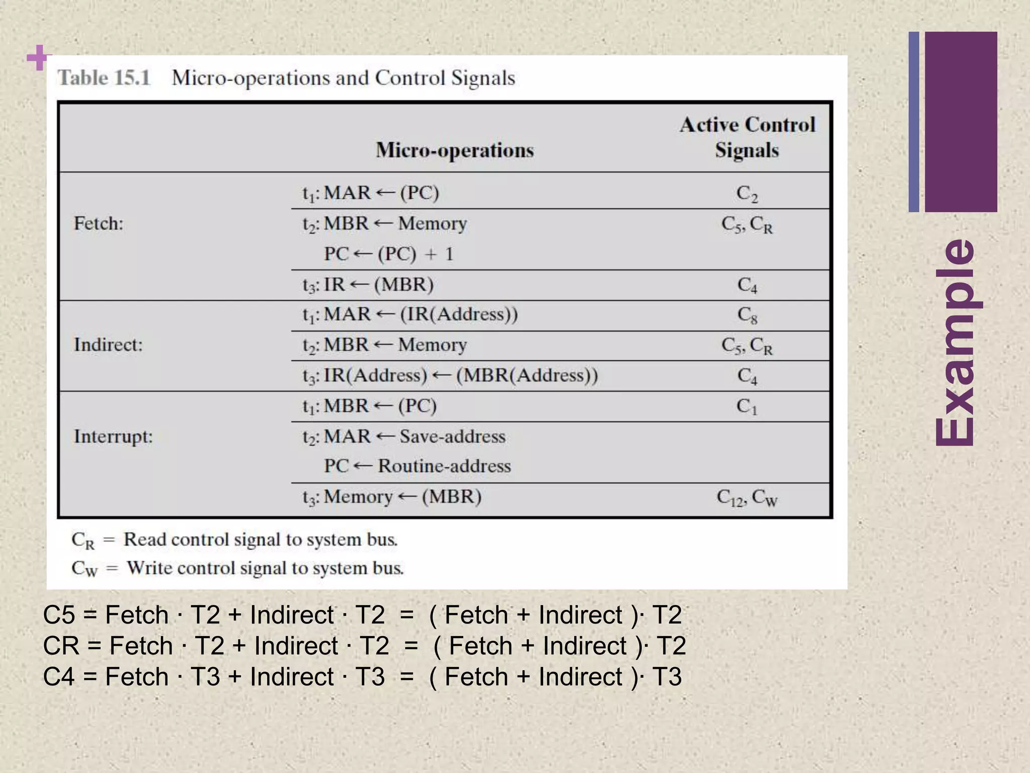
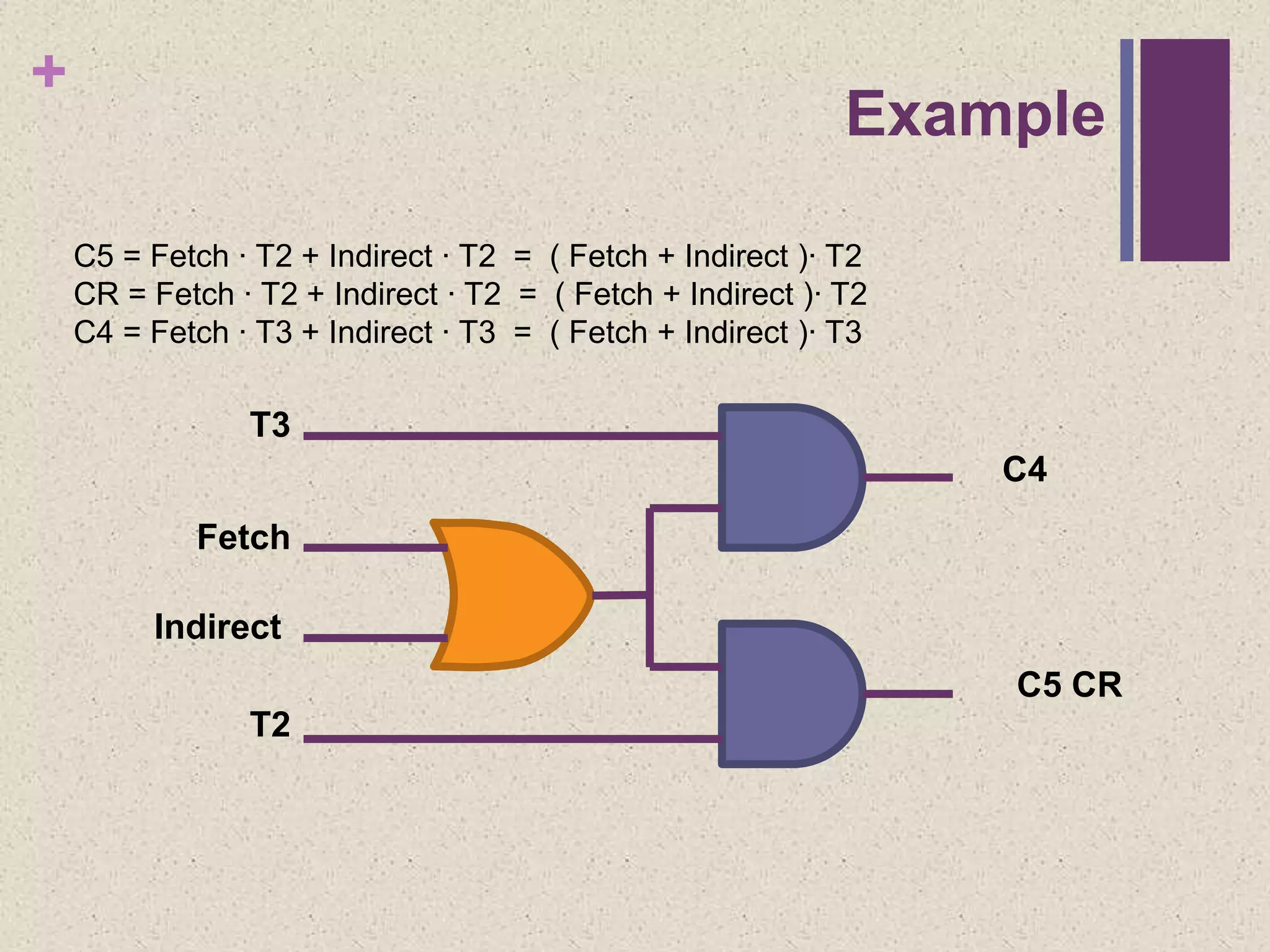
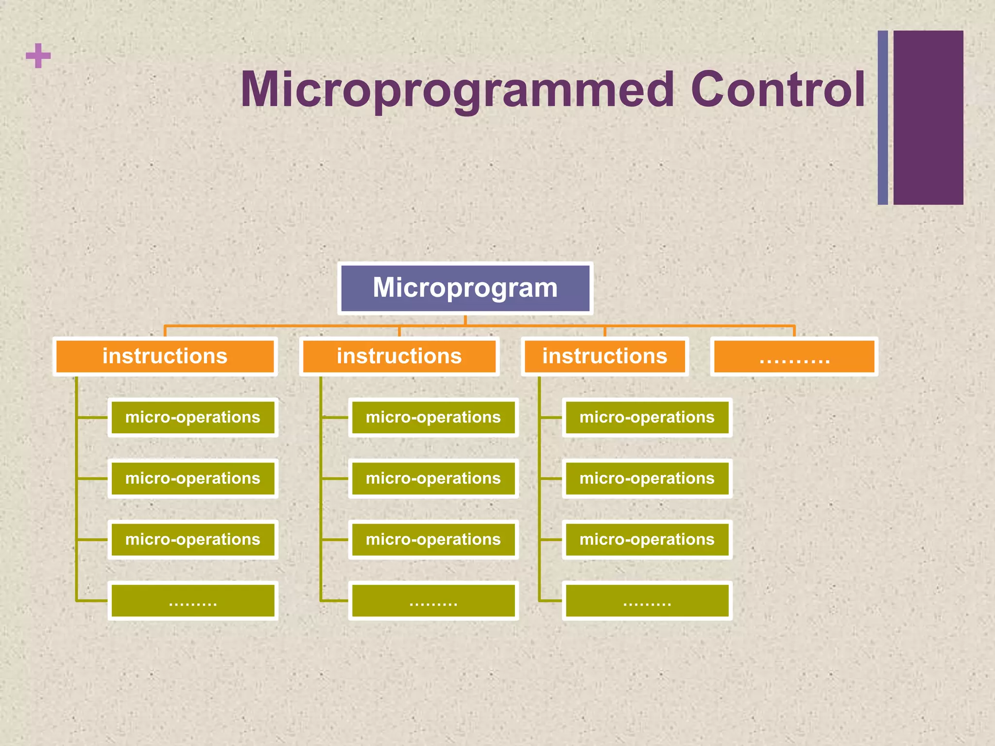
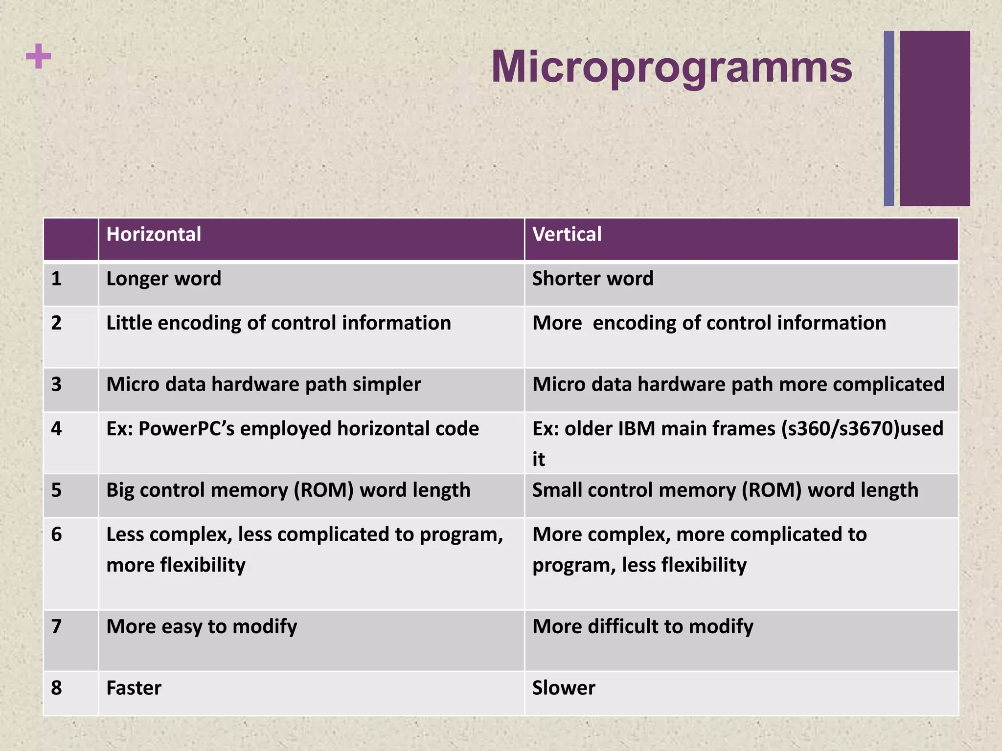
KEMBAR78
Computer architecture control unit | PPTX
+
Control Unit
Lecturer by
Mazin Adnan
+
Outline
 Control Unit
 Control Signals
 Control word
 Control Registers
 Control Cycle
 Control Unit Implementation
 Hardwired Control
 Microprogramed Control
 Horizontal
 Vertical
+
Control Unit
 Control Unit (CU) is a component of a computer's central
processing unit (CPU) that performs two tasks:
1. It causes the processor to step through a series of micro-
operations in the proper sequence, based on the program being
executed.
2. it generates the control signals that cause each micro-operation to
be executed.
+
Control Unit
+
Control Unit
Control Signals
 Group of bits used to opening and closing of logic
gates, resulting in the transfer of data to and from
registers (or memory and I/O modules) and the
operation of the ALU.
Control word
 The combination of bits which each bit represents
one control line.
 Each microoperation represented by a different
pattern of 1s and 0s in the control word
5
1 0 1 0 0 0 1 0
+
Control Signals (The inputs)
1. Clock
 An electronic device in a computer that issues a steady high-
frequency signal that synchronizes all the internal components
2. Instruction register
 The opcode and addressing mode of the current instruction are
used to determine which micro-operations to perform during the
execute cycle
3. Flags
A. State of processor
B. outcome of previous ALU operations
4. From control bus
 portion of the system bus
+
Control Signals (The outputs)
1. Within CPU
A. Cause data movement between registers
B. Activate specific ALU functions
2. Via control bus
A. To memory
B. To I/O modules
+
Control Registers Utilized
Control Cycle
 Program Counter (PC)
 Holds address of next instruction to be fetched
 Memory Address Register (MAR)
 Connected to address bus
 Specifies address for read or write from or to memory
 Memory Buffer Register (MBR)
 Connected to data bus
 Holds data to write or last data read
 Instruction Register (IR)
 Holds last instruction fetched
+
Constituent Elements of Program
Execution
+
Fetch Sequence
 Address of next instruction is in PC
 Address (MAR) is placed on address bus
 Control unit issues READ command
 Result (data from memory) appears on data bus
 Data from data bus copied into MBR
 PC incremented by 1 (in parallel with data fetch from memory)
 Data (instruction) moved from MBR to IR
 MBR is now free for further data fetches
00000000011001000000000001100100
Main Memory
Control Unit
R
0011100001101110
0011100001101110
MAR
MBR
PC
IR
AC
Fetch Cycle
+10000000001100101
t1: MAR <- (PC)
t2: MBR <- (memory)
PC <- (PC) +1
t3: IR <- (MBR)
0000000001100100
+
Fetch Sequence (get data)
 t1: MAR <- (PC)
 t2: MBR <- (memory)
PC <- (PC) +1
 t3: IR <- (MBR)
OR
 t1: MAR <- (PC)
 t2: MBR <- (memory)
 t3: PC <- (PC) +1
IR <- (MBR)
+
Rules for Clock Cycle Grouping
 Proper sequence must be followed
 MAR <- (PC) must precede MBR <- (memory)
 Conflicts must be avoided
 Must not read & write same register at same time
 MBR <- (memory) & IR <- (MBR) must not be in same cycle
 Also: PC <- (PC) +1 involves addition
 Use ALU
 May need additional micro-operations
00000000011001000000000001100100
Main Memory
Control Unit
R
0011100001101110
0011100001101110
MAR
MBR
PC
IR
AC
Indirect Cycle
t1: MAR <- (IR (Address))
t2: MBR <- (memory)
t3: IR (Address) <- MBR
(Address)
0000000001100100
+
Indirect Cycle (get address)
 MAR <- (IRaddress) - address field of IR
 MBR <- (memory)
 IRaddress <- (MBRaddress)
 MBR contains an address
 IR is now in same state as if direct addressing had been used
 (What does this say about IR size?)
0000000001100100
0100101101101001
Main Memory
Control Unit
W
0011100001101110
MAR
MBR
PC
IR
AC
Interrupt Cycle
t1: MBR <-(PC)
t2: MAR <- save-address
PC <- routine-address
t3: memory <- (MBR)
0000000001100100
0000000001100100
+
Interrupt Cycle
 t1: MBR <-(PC)
 t2: MAR <- save-address
 PC <- routine-address
 t3: memory <- (MBR)
 This is a minimum
 May be additional micro-ops to get addresses
00000000011001000000000001100100
Main Memory
Control Unit
R
0011100001101110
MAR
MBR
PC
IR
AC
Execute Cycle (ADD)
t1: MAR <- (IR (Address))
t2: MBR <- (memory)
t3: R1 <- R1 + (MBR)
0000000001100100
0000001101100000R1
+
0011101111001110
+
Execute Cycle (ADD)
 Different for each instruction
 e.g. ADD R1,X - add the contents of location X to Register 1 ,
result in R1
 t1: MAR <- (IRaddress)
 t2: MBR <- (memory)
 t3: R1 <- R1 + (MBR)
+
Control Unit Implementation
 A wide variety of techniques have been used. Most of these
fall into one of two categories:
 Hardwired control:
 Microprogrammed control
20
+
Hardwired control
 The control unit is essentially a state machine circuit. Its
input logic signals are transformed into a set of output
logic signals, which are the control signals
+ 22
Hardwired Control
+
Decoder Table
+
Example
+
Example
C5 = Fetch ∙ T2 + Indirect ∙ T2 = ( Fetch + Indirect )∙ T2
CR = Fetch ∙ T2 + Indirect ∙ T2 = ( Fetch + Indirect )∙ T2
C4 = Fetch ∙ T3 + Indirect ∙ T3 = ( Fetch + Indirect )∙ T3
+
Example
C4
C5 CR
T3
T2
Fetch
Indirect
C5 = Fetch ∙ T2 + Indirect ∙ T2 = ( Fetch + Indirect )∙ T2
CR = Fetch ∙ T2 + Indirect ∙ T2 = ( Fetch + Indirect )∙ T2
C4 = Fetch ∙ T3 + Indirect ∙ T3 = ( Fetch + Indirect )∙ T3
+
 The logic in Micro-programmed control unit is
specified by a microprogram
 Microprogram (Firmware) consists of a sequence of
instructions in a microprogramming language
 Instructions specify set of
micro-operations (microinstructions)
27
Microprogrammed Control
+
Microprogrammed Control
Microprogram
instructions
micro-operations
micro-operations
micro-operations
………
instructions
micro-operations
micro-operations
micro-operations
………
instructions
micro-operations
micro-operations
micro-operations
………
……….
MicroprogrammedControl
+
MicroprogrammedControl
+
Organization of Control Memory
•
•
•
Jump to indirect or execute
•
•
•
Jump to execute
•
•
•
Jump to fetch
Jump to opcode routine
•
•
•
Jump to fetch or interrupt
Fetch cycle routine
Indirect cycle routine
Interrupt cycle routine
Execute cycle routine
ADD routine
•
•
•
•
•
•
+ Compare Hard Wired and Microprogramed
Hardwired Microprogrammed
1 Uses logic gates and other digital
circuits
Uses microprogramming
language
2 As the name implies it is a
hardware control unit
As the name implies it is a
software control unit.
3 The decoders and sequencing
logic unit are very complex
pieces of logic
The decoders and sequencing
logic unit
are very simple pieces of logic
4 Difficult to design, test and
implement compared to
microprogrammed
Easy to design, test and
implement compared to
hardwired
+ Compare Hard Wired and Microprogramed
Hardwired Microprogrammed
5 Inflexible to modify Flexible to modify.
6 Expensive and high error prone
to implement
Cheaper and less error prone to
implement
7 Used in RISC processor Used in CISC processor
8 Faster than micro- programmed
control unit
Slower than micro- programmed
control unit
+
Microinstruction Control Signals
for the add Instruction
 Addresses 101–103 are the instruction fetch
 Addresses 200–202 do the add
 Change of control from 103 to 200 uses a kind of branch
.
101
102
103
200
201
202
• • •
• • •
• • •
• • •
• • •
• • •
1 0 0 0 1 1 0 0 0 0 1 1 0 0 0 0 0 0
0 1 0 0 0 0 1 0 0 0 0 0 1 0 0 0 0 0
0 0 1 0 0 0 0 1 0 0 0 0 0 0 0 0 0 0
0
0
0
0 0 1 1 10 0 0 0 0 0 0 0 0 0 0 0
1 1 1 10 0 0 0 0 0 0 00 0 0 0 0
1 0 0 0 0 0 0 0 1 0 0 0 0 0 01 1
+
 In horizontal microcode, each control signal is
represented by a bit in the instruction
 Fewer control store words of more bits per word
 In vertical microcode, a set of true control signals
is represented by a shorter code
 more compact (fewer bits) than horizontal
microinstructions
 small additional amount of logic and time delay
than horizontal microinstructions
Microprogrammed Types
+
Microinstruction Formats
+
Horizontal vs. Vertical
+ Example Microprogramming Formats
Horizontal vs
Vertical
+
horizontal
+
Vertical Microprogramming
000: NO OP
001: PC ABUS
010: IR ABUS
011: MBR MBUS
100: MAR M
101: AC RBUS
110: ALU Res RBUS
00 = Wait
01 = AC<15>
10 = IR<15>
11 = IR<14>
Register Transfer Format
0 Source Destination Operation
1 3 3 3
000: NO OP
001: RBUSAC
010: MBUSIR
011: ABUS MAR
100: M MBR
101: RBUSMBR
110: ABUS PC
111: MBR M
000: NO OP
001: ALU ADD
010: ALU PASS B
011: 0 PC
100: PC + 1PC
101: Read
110: Write
+ Vertical Microprogramming
ROM ADDRESS SYMBOLIC CONTENTS BINARY CONTENTS
000000 RES RT PC  MAR, PC +1  PC 0 001 011 100
000001 IF0 RT MAR  M, Read 0 100 000 101
000010 BJ Wait=0, IF0 1 000 000 001
000011 IF1 RT MAR  M, M  MBR, Read 0 100 100 101
000100 BJ Wait=1, IF1 1 001 000 011
000101 IF2 RT MBR  IR 0 011 010 000
000110 BJ Wait=0, IF2 1 000 000 101
000111 RT IR  MAR 0 010 011 000
001000 OD BJ IR<15>=1, OD1 1 101 010 101
001001 BJ IR<14>=1, ST0 1 111 010 000
001010 LD0 RT MAR  M, Read 0 100 000 101
001011 LD1 RT MAR  M, M  MBR, Read 0 100 100 101
001100 BJ Wait=1, LD1 1 001 001 011
001101 LD2 RT MBR  AC 0 110 001 010
001110 BJ Wait=0, RES 1 000 000 000
001111 BJ Wait=1, RES 1 001 000 000
+ Microprogramms
Horizontal Vertical
1 Longer word Shorter word
2 Little encoding of control information More encoding of control information
3 Micro data hardware path simpler Micro data hardware path more complicated
4 Ex: PowerPC’s employed horizontal code Ex: older IBM main frames (s360/s3670)used
it
5 Big control memory (ROM) word length Small control memory (ROM) word length
6 Less complex, less complicated to program,
more flexibility
More complex, more complicated to
program, less flexibility
7 More easy to modify More difficult to modify
8 Faster Slower
+
Thank you

Computer architecture control unit

  • 1.
  • 2.
    + Outline  Control Unit Control Signals  Control word  Control Registers  Control Cycle  Control Unit Implementation  Hardwired Control  Microprogramed Control  Horizontal  Vertical
  • 3.
    + Control Unit  ControlUnit (CU) is a component of a computer's central processing unit (CPU) that performs two tasks: 1. It causes the processor to step through a series of micro- operations in the proper sequence, based on the program being executed. 2. it generates the control signals that cause each micro-operation to be executed.
  • 4.
  • 5.
    + Control Unit Control Signals Group of bits used to opening and closing of logic gates, resulting in the transfer of data to and from registers (or memory and I/O modules) and the operation of the ALU. Control word  The combination of bits which each bit represents one control line.  Each microoperation represented by a different pattern of 1s and 0s in the control word 5 1 0 1 0 0 0 1 0
  • 6.
    + Control Signals (Theinputs) 1. Clock  An electronic device in a computer that issues a steady high- frequency signal that synchronizes all the internal components 2. Instruction register  The opcode and addressing mode of the current instruction are used to determine which micro-operations to perform during the execute cycle 3. Flags A. State of processor B. outcome of previous ALU operations 4. From control bus  portion of the system bus
  • 7.
    + Control Signals (Theoutputs) 1. Within CPU A. Cause data movement between registers B. Activate specific ALU functions 2. Via control bus A. To memory B. To I/O modules
  • 8.
    + Control Registers Utilized ControlCycle  Program Counter (PC)  Holds address of next instruction to be fetched  Memory Address Register (MAR)  Connected to address bus  Specifies address for read or write from or to memory  Memory Buffer Register (MBR)  Connected to data bus  Holds data to write or last data read  Instruction Register (IR)  Holds last instruction fetched
  • 9.
    + Constituent Elements ofProgram Execution
  • 10.
    + Fetch Sequence  Addressof next instruction is in PC  Address (MAR) is placed on address bus  Control unit issues READ command  Result (data from memory) appears on data bus  Data from data bus copied into MBR  PC incremented by 1 (in parallel with data fetch from memory)  Data (instruction) moved from MBR to IR  MBR is now free for further data fetches
  • 11.
    00000000011001000000000001100100 Main Memory Control Unit R 0011100001101110 0011100001101110 MAR MBR PC IR AC FetchCycle +10000000001100101 t1: MAR <- (PC) t2: MBR <- (memory) PC <- (PC) +1 t3: IR <- (MBR) 0000000001100100
  • 12.
    + Fetch Sequence (getdata)  t1: MAR <- (PC)  t2: MBR <- (memory) PC <- (PC) +1  t3: IR <- (MBR) OR  t1: MAR <- (PC)  t2: MBR <- (memory)  t3: PC <- (PC) +1 IR <- (MBR)
  • 13.
    + Rules for ClockCycle Grouping  Proper sequence must be followed  MAR <- (PC) must precede MBR <- (memory)  Conflicts must be avoided  Must not read & write same register at same time  MBR <- (memory) & IR <- (MBR) must not be in same cycle  Also: PC <- (PC) +1 involves addition  Use ALU  May need additional micro-operations
  • 14.
    00000000011001000000000001100100 Main Memory Control Unit R 0011100001101110 0011100001101110 MAR MBR PC IR AC IndirectCycle t1: MAR <- (IR (Address)) t2: MBR <- (memory) t3: IR (Address) <- MBR (Address) 0000000001100100
  • 15.
    + Indirect Cycle (getaddress)  MAR <- (IRaddress) - address field of IR  MBR <- (memory)  IRaddress <- (MBRaddress)  MBR contains an address  IR is now in same state as if direct addressing had been used  (What does this say about IR size?)
  • 16.
    0000000001100100 0100101101101001 Main Memory Control Unit W 0011100001101110 MAR MBR PC IR AC InterruptCycle t1: MBR <-(PC) t2: MAR <- save-address PC <- routine-address t3: memory <- (MBR) 0000000001100100 0000000001100100
  • 17.
    + Interrupt Cycle  t1:MBR <-(PC)  t2: MAR <- save-address  PC <- routine-address  t3: memory <- (MBR)  This is a minimum  May be additional micro-ops to get addresses
  • 18.
    00000000011001000000000001100100 Main Memory Control Unit R 0011100001101110 MAR MBR PC IR AC ExecuteCycle (ADD) t1: MAR <- (IR (Address)) t2: MBR <- (memory) t3: R1 <- R1 + (MBR) 0000000001100100 0000001101100000R1 + 0011101111001110
  • 19.
    + Execute Cycle (ADD) Different for each instruction  e.g. ADD R1,X - add the contents of location X to Register 1 , result in R1  t1: MAR <- (IRaddress)  t2: MBR <- (memory)  t3: R1 <- R1 + (MBR)
  • 20.
    + Control Unit Implementation A wide variety of techniques have been used. Most of these fall into one of two categories:  Hardwired control:  Microprogrammed control 20
  • 21.
    + Hardwired control  Thecontrol unit is essentially a state machine circuit. Its input logic signals are transformed into a set of output logic signals, which are the control signals
  • 22.
  • 23.
  • 24.
  • 25.
    + Example C5 = Fetch∙ T2 + Indirect ∙ T2 = ( Fetch + Indirect )∙ T2 CR = Fetch ∙ T2 + Indirect ∙ T2 = ( Fetch + Indirect )∙ T2 C4 = Fetch ∙ T3 + Indirect ∙ T3 = ( Fetch + Indirect )∙ T3
  • 26.
    + Example C4 C5 CR T3 T2 Fetch Indirect C5 =Fetch ∙ T2 + Indirect ∙ T2 = ( Fetch + Indirect )∙ T2 CR = Fetch ∙ T2 + Indirect ∙ T2 = ( Fetch + Indirect )∙ T2 C4 = Fetch ∙ T3 + Indirect ∙ T3 = ( Fetch + Indirect )∙ T3
  • 27.
    +  The logicin Micro-programmed control unit is specified by a microprogram  Microprogram (Firmware) consists of a sequence of instructions in a microprogramming language  Instructions specify set of micro-operations (microinstructions) 27 Microprogrammed Control
  • 28.
  • 29.
  • 30.
  • 31.
  • 32.
    + Organization of ControlMemory • • • Jump to indirect or execute • • • Jump to execute • • • Jump to fetch Jump to opcode routine • • • Jump to fetch or interrupt Fetch cycle routine Indirect cycle routine Interrupt cycle routine Execute cycle routine ADD routine • • • • • •
  • 33.
    + Compare HardWired and Microprogramed Hardwired Microprogrammed 1 Uses logic gates and other digital circuits Uses microprogramming language 2 As the name implies it is a hardware control unit As the name implies it is a software control unit. 3 The decoders and sequencing logic unit are very complex pieces of logic The decoders and sequencing logic unit are very simple pieces of logic 4 Difficult to design, test and implement compared to microprogrammed Easy to design, test and implement compared to hardwired
  • 34.
    + Compare HardWired and Microprogramed Hardwired Microprogrammed 5 Inflexible to modify Flexible to modify. 6 Expensive and high error prone to implement Cheaper and less error prone to implement 7 Used in RISC processor Used in CISC processor 8 Faster than micro- programmed control unit Slower than micro- programmed control unit
  • 35.
    + Microinstruction Control Signals forthe add Instruction  Addresses 101–103 are the instruction fetch  Addresses 200–202 do the add  Change of control from 103 to 200 uses a kind of branch . 101 102 103 200 201 202 • • • • • • • • • • • • • • • • • • 1 0 0 0 1 1 0 0 0 0 1 1 0 0 0 0 0 0 0 1 0 0 0 0 1 0 0 0 0 0 1 0 0 0 0 0 0 0 1 0 0 0 0 1 0 0 0 0 0 0 0 0 0 0 0 0 0 0 0 1 1 10 0 0 0 0 0 0 0 0 0 0 0 1 1 1 10 0 0 0 0 0 0 00 0 0 0 0 1 0 0 0 0 0 0 0 1 0 0 0 0 0 01 1
  • 36.
    +  In horizontalmicrocode, each control signal is represented by a bit in the instruction  Fewer control store words of more bits per word  In vertical microcode, a set of true control signals is represented by a shorter code  more compact (fewer bits) than horizontal microinstructions  small additional amount of logic and time delay than horizontal microinstructions Microprogrammed Types
  • 37.
  • 38.
  • 39.
    + Example MicroprogrammingFormats Horizontal vs Vertical
  • 40.
  • 41.
    + Vertical Microprogramming 000: NOOP 001: PC ABUS 010: IR ABUS 011: MBR MBUS 100: MAR M 101: AC RBUS 110: ALU Res RBUS 00 = Wait 01 = AC<15> 10 = IR<15> 11 = IR<14> Register Transfer Format 0 Source Destination Operation 1 3 3 3 000: NO OP 001: RBUSAC 010: MBUSIR 011: ABUS MAR 100: M MBR 101: RBUSMBR 110: ABUS PC 111: MBR M 000: NO OP 001: ALU ADD 010: ALU PASS B 011: 0 PC 100: PC + 1PC 101: Read 110: Write
  • 42.
    + Vertical Microprogramming ROMADDRESS SYMBOLIC CONTENTS BINARY CONTENTS 000000 RES RT PC  MAR, PC +1  PC 0 001 011 100 000001 IF0 RT MAR  M, Read 0 100 000 101 000010 BJ Wait=0, IF0 1 000 000 001 000011 IF1 RT MAR  M, M  MBR, Read 0 100 100 101 000100 BJ Wait=1, IF1 1 001 000 011 000101 IF2 RT MBR  IR 0 011 010 000 000110 BJ Wait=0, IF2 1 000 000 101 000111 RT IR  MAR 0 010 011 000 001000 OD BJ IR<15>=1, OD1 1 101 010 101 001001 BJ IR<14>=1, ST0 1 111 010 000 001010 LD0 RT MAR  M, Read 0 100 000 101 001011 LD1 RT MAR  M, M  MBR, Read 0 100 100 101 001100 BJ Wait=1, LD1 1 001 001 011 001101 LD2 RT MBR  AC 0 110 001 010 001110 BJ Wait=0, RES 1 000 000 000 001111 BJ Wait=1, RES 1 001 000 000
  • 43.
    + Microprogramms Horizontal Vertical 1Longer word Shorter word 2 Little encoding of control information More encoding of control information 3 Micro data hardware path simpler Micro data hardware path more complicated 4 Ex: PowerPC’s employed horizontal code Ex: older IBM main frames (s360/s3670)used it 5 Big control memory (ROM) word length Small control memory (ROM) word length 6 Less complex, less complicated to program, more flexibility More complex, more complicated to program, less flexibility 7 More easy to modify More difficult to modify 8 Faster Slower
  • 44.