Downloaded 2,573 times
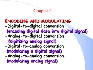


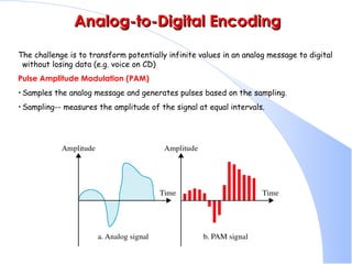
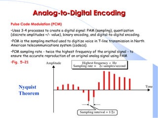
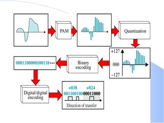
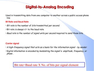


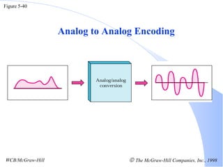
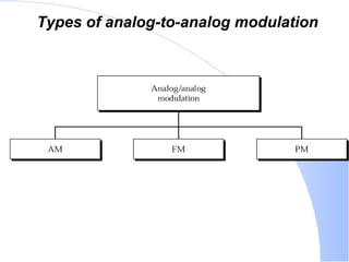

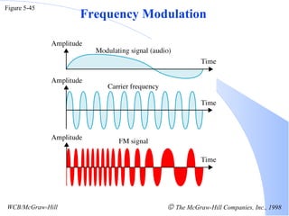
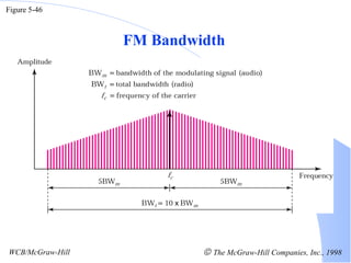
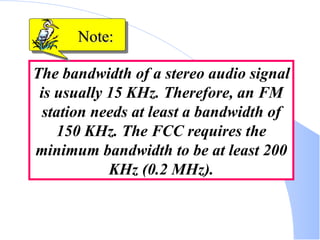
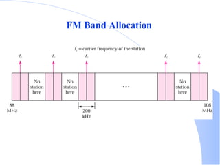
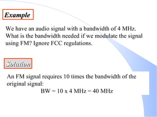
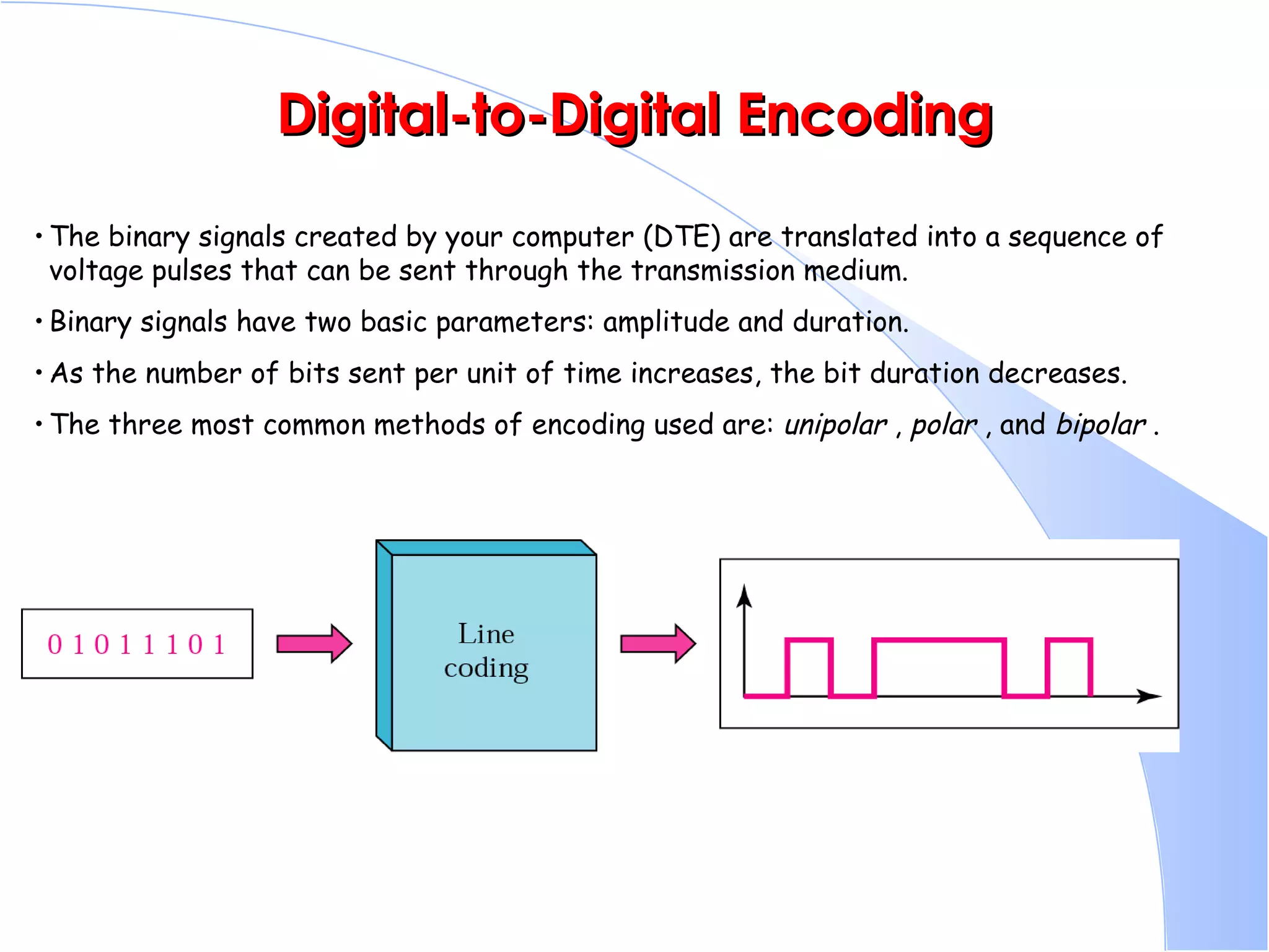
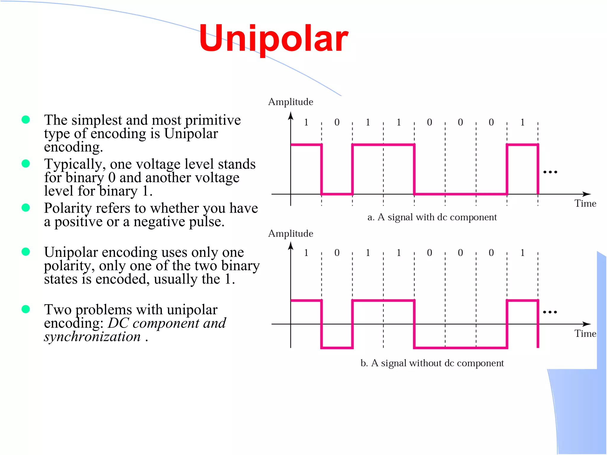
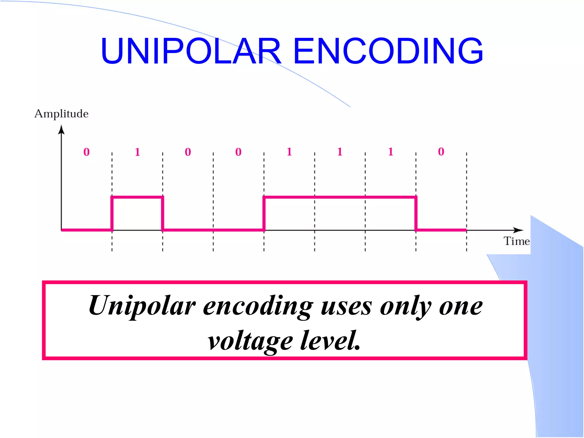
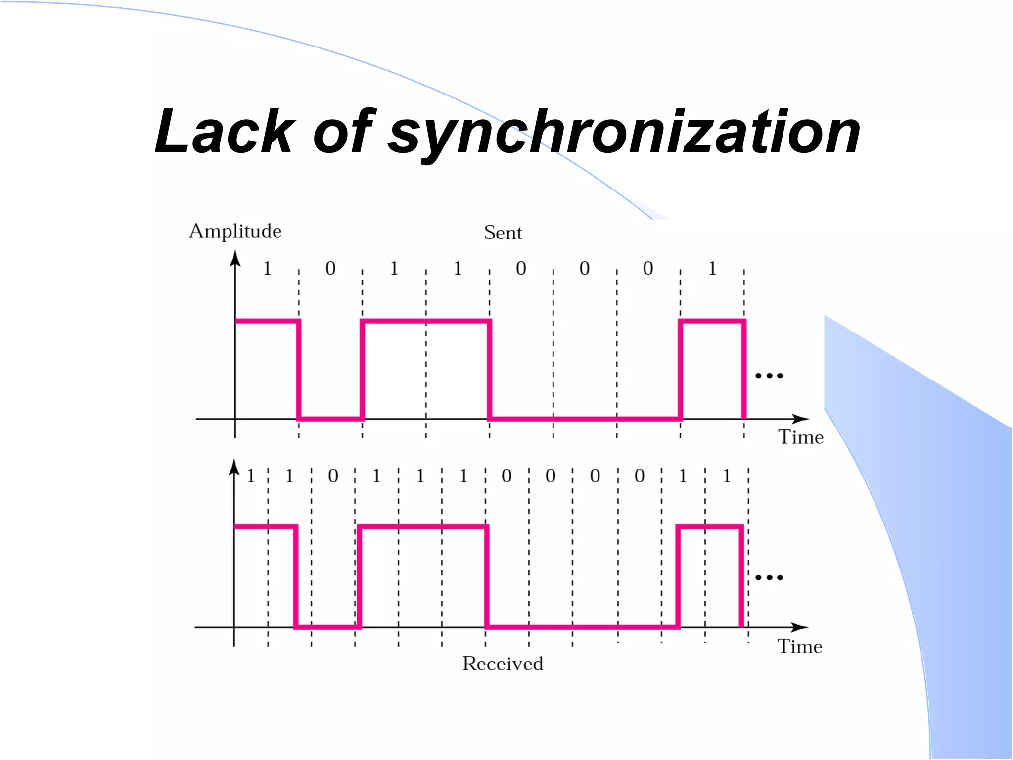
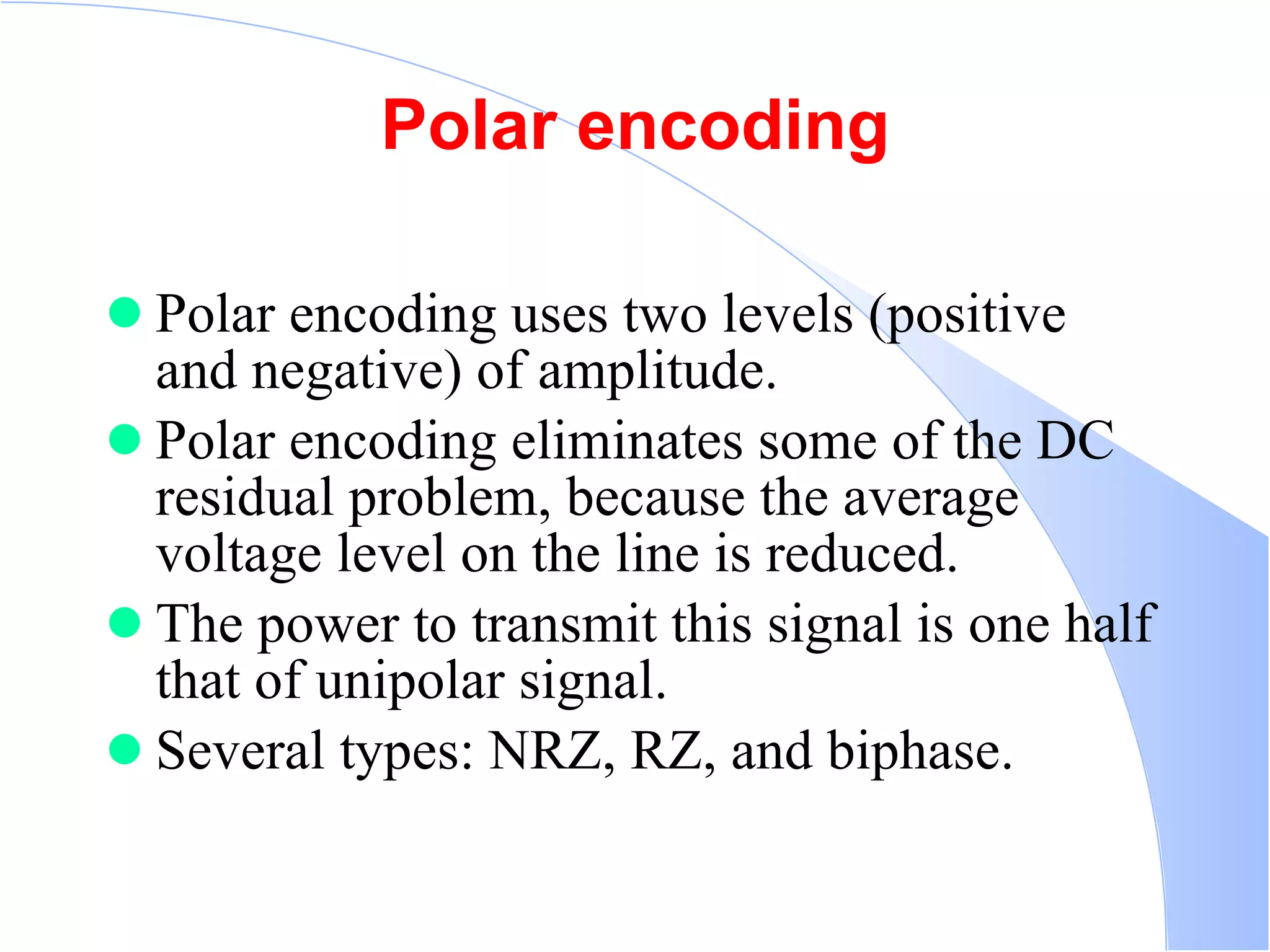
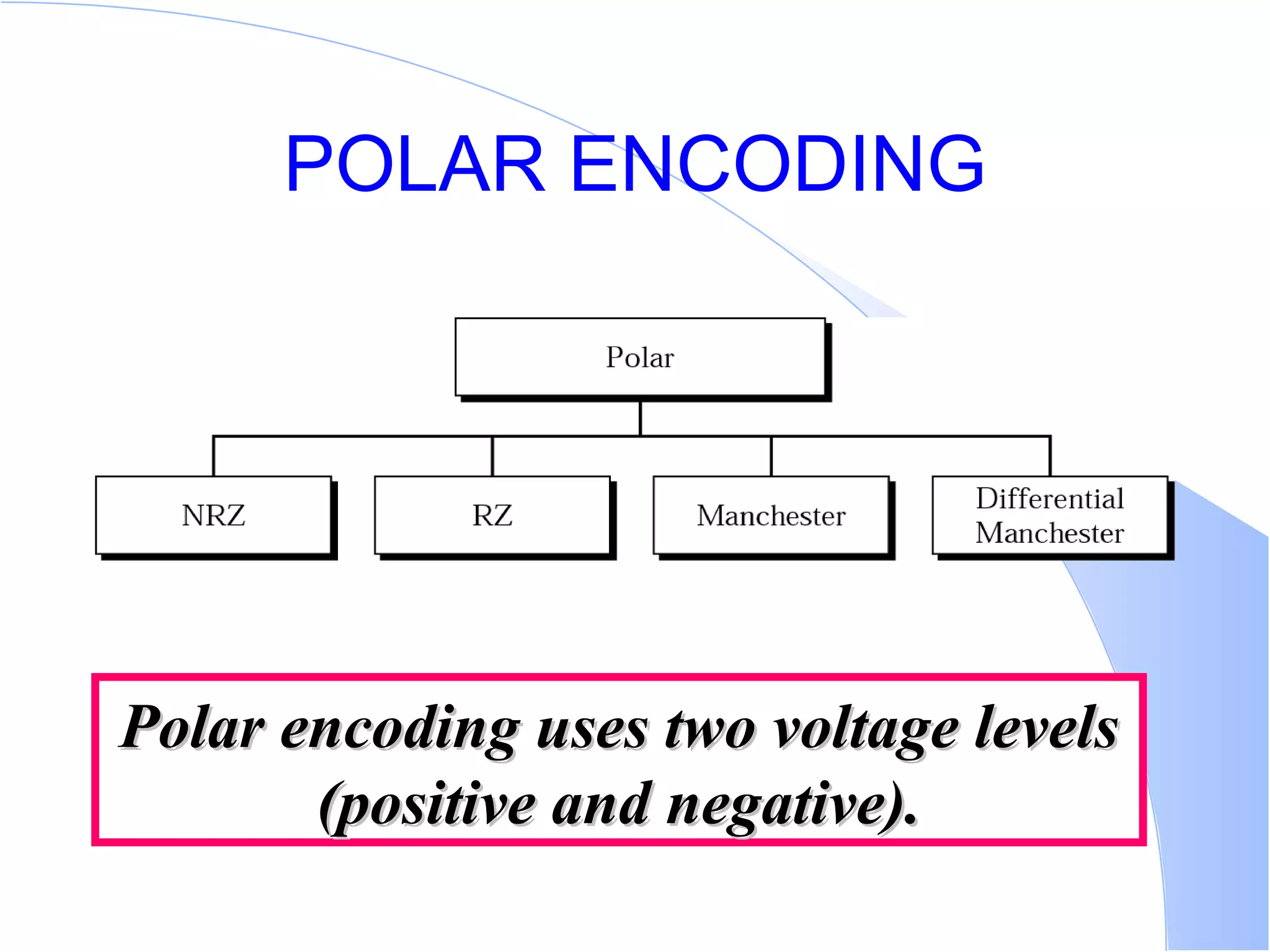


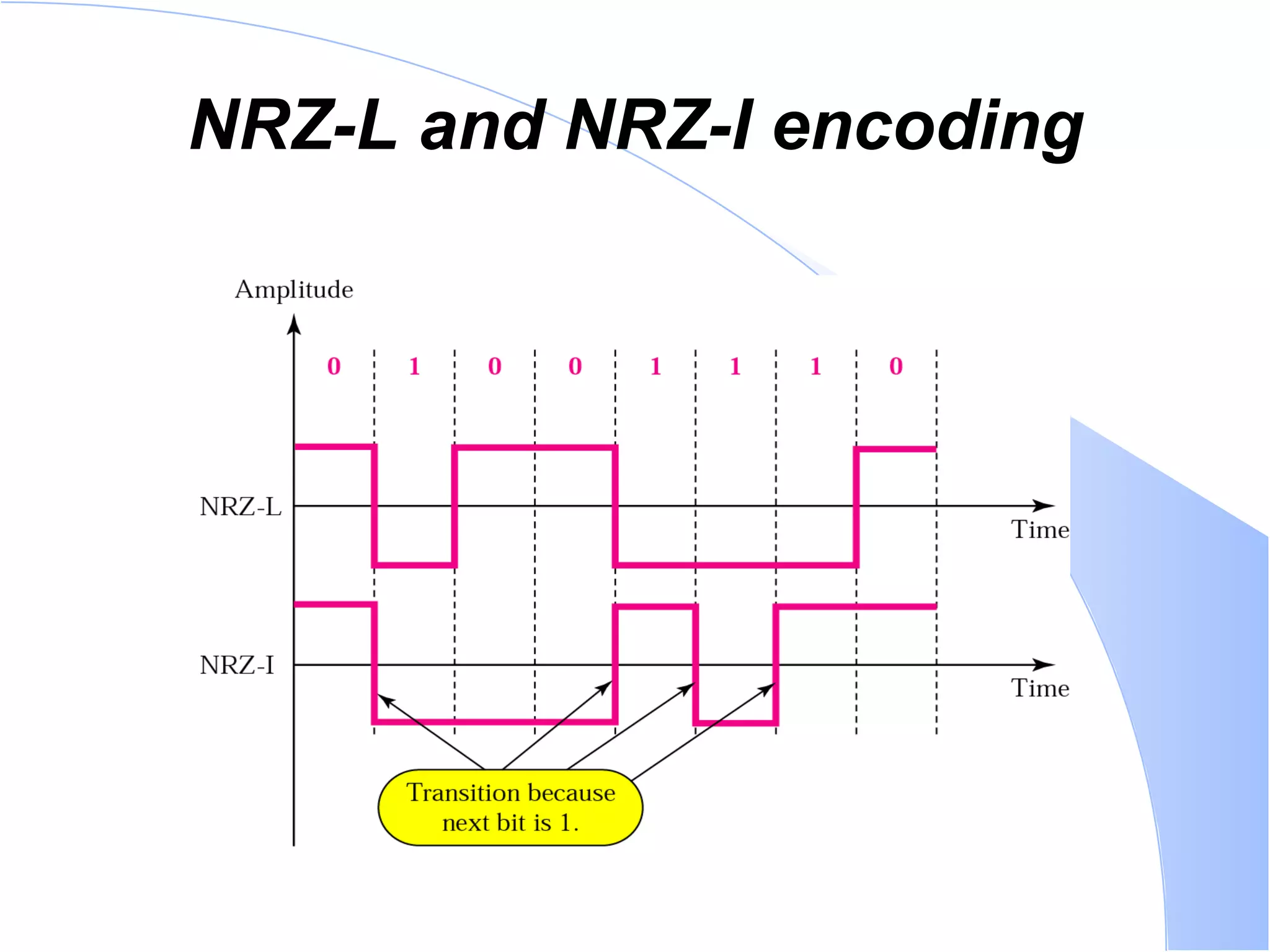
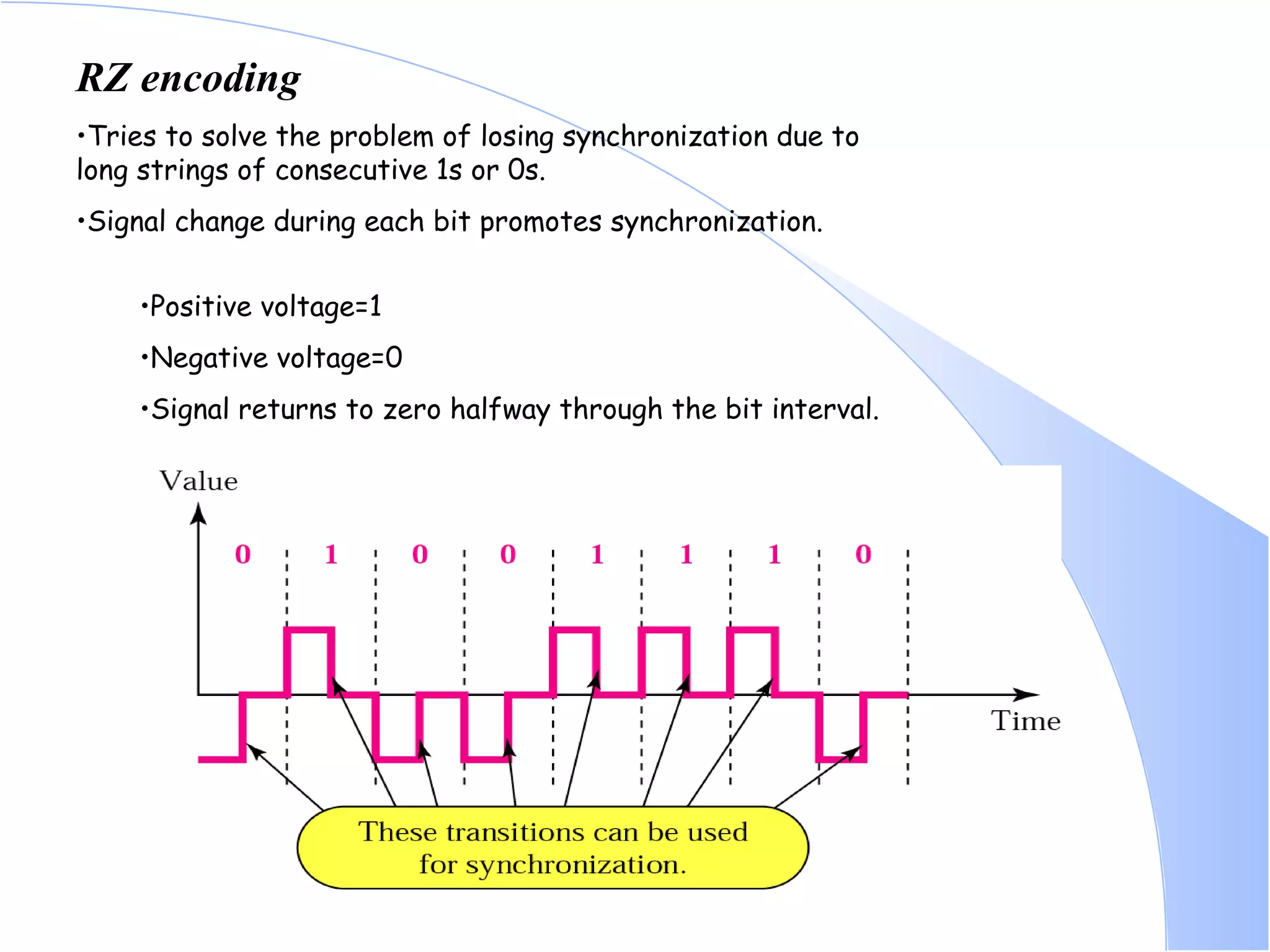

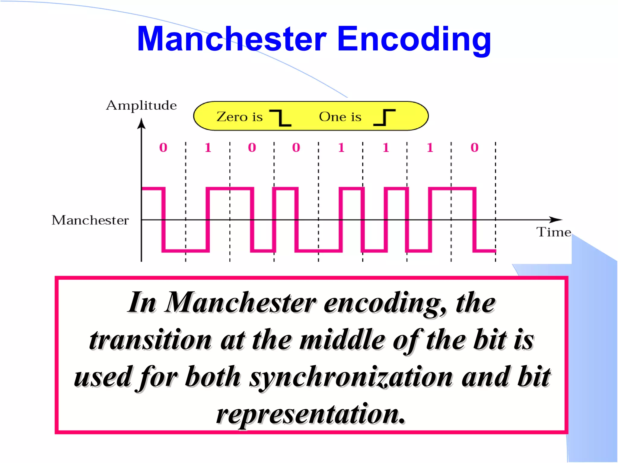


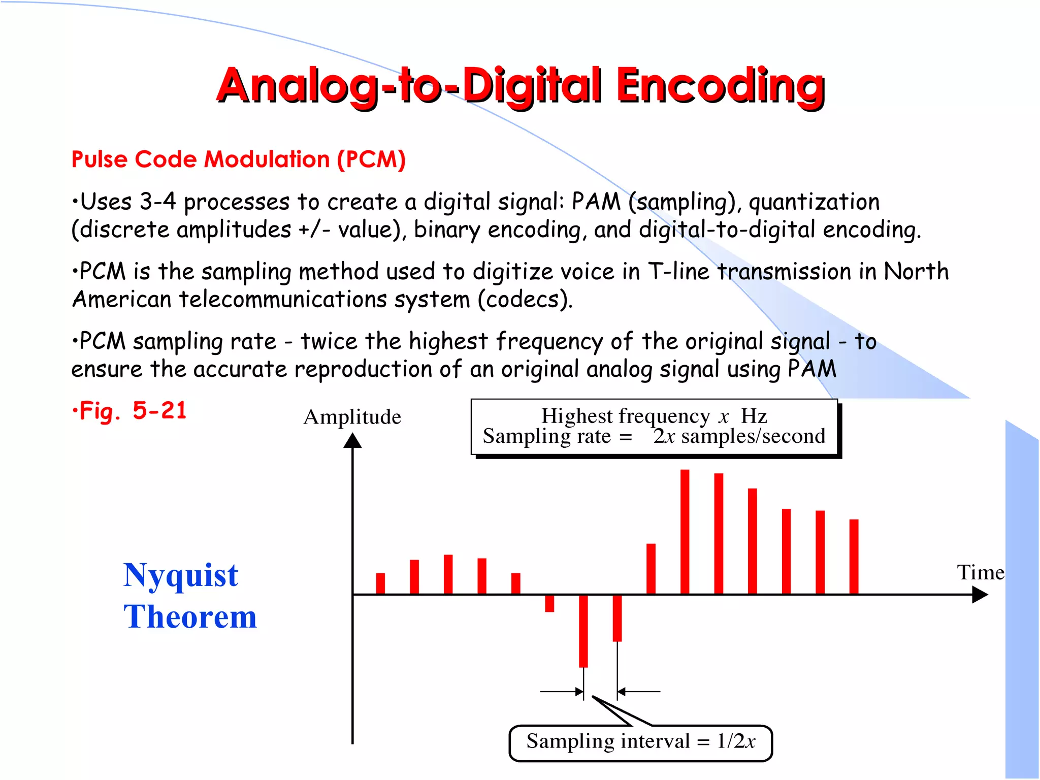
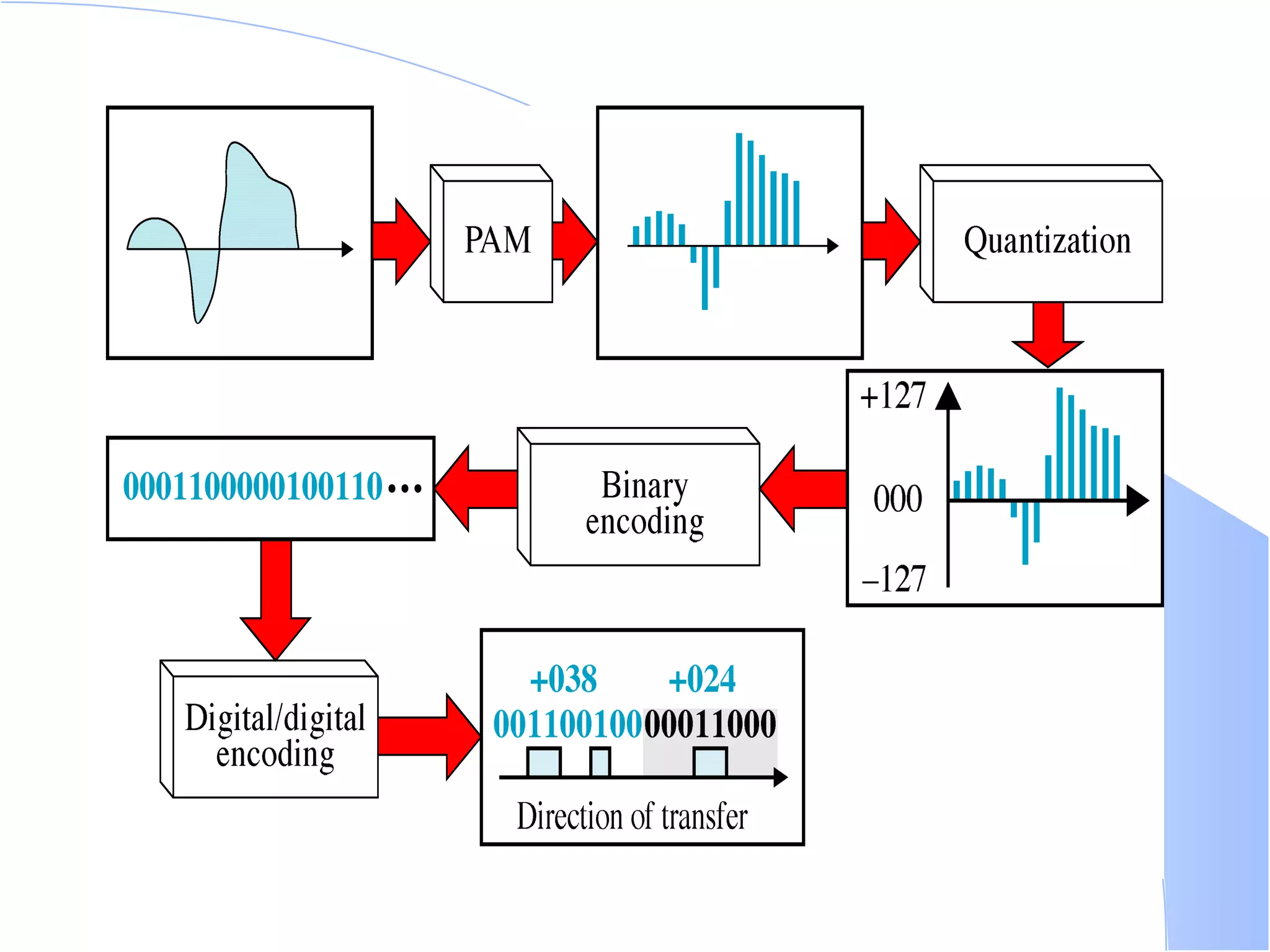
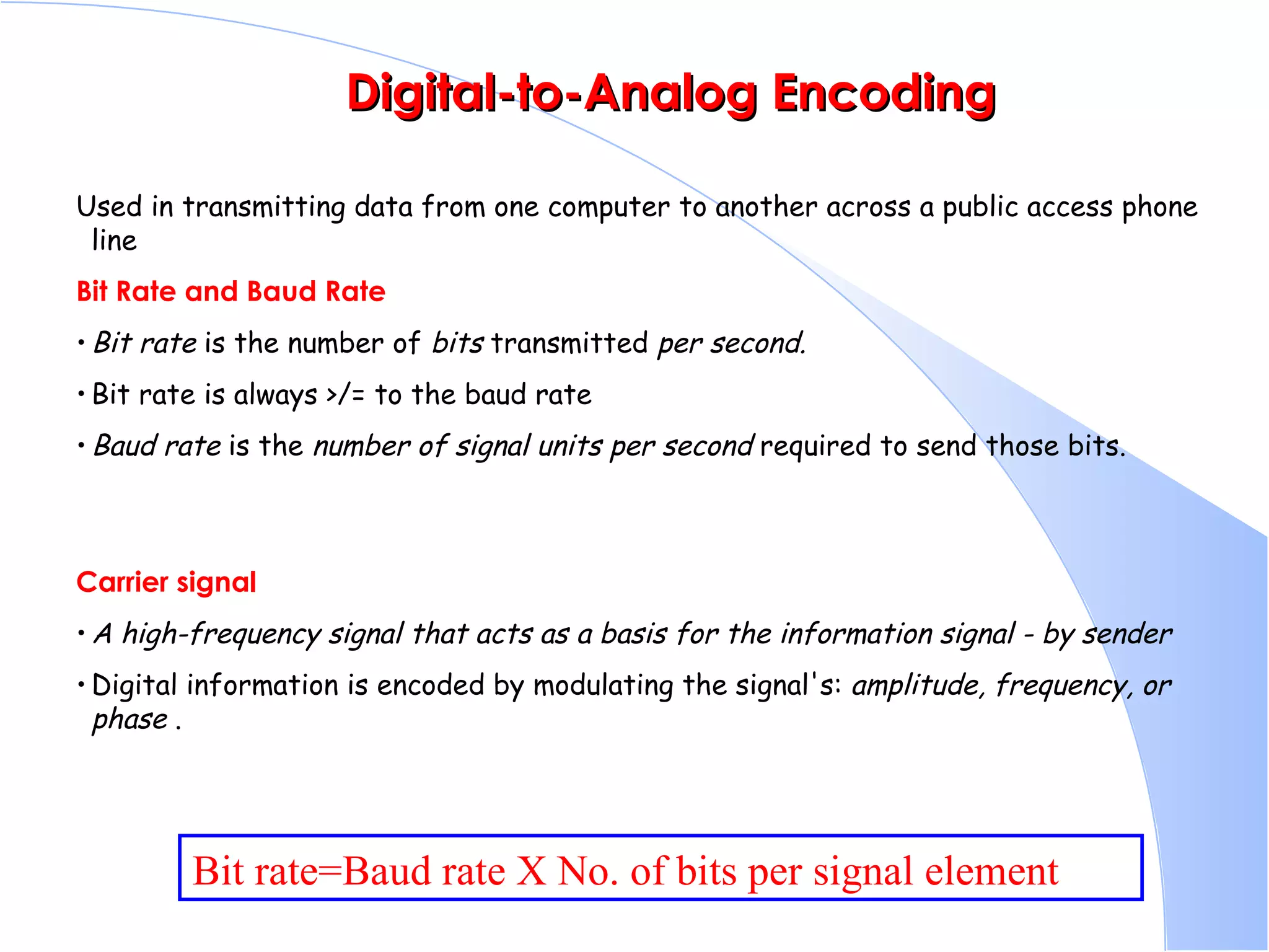


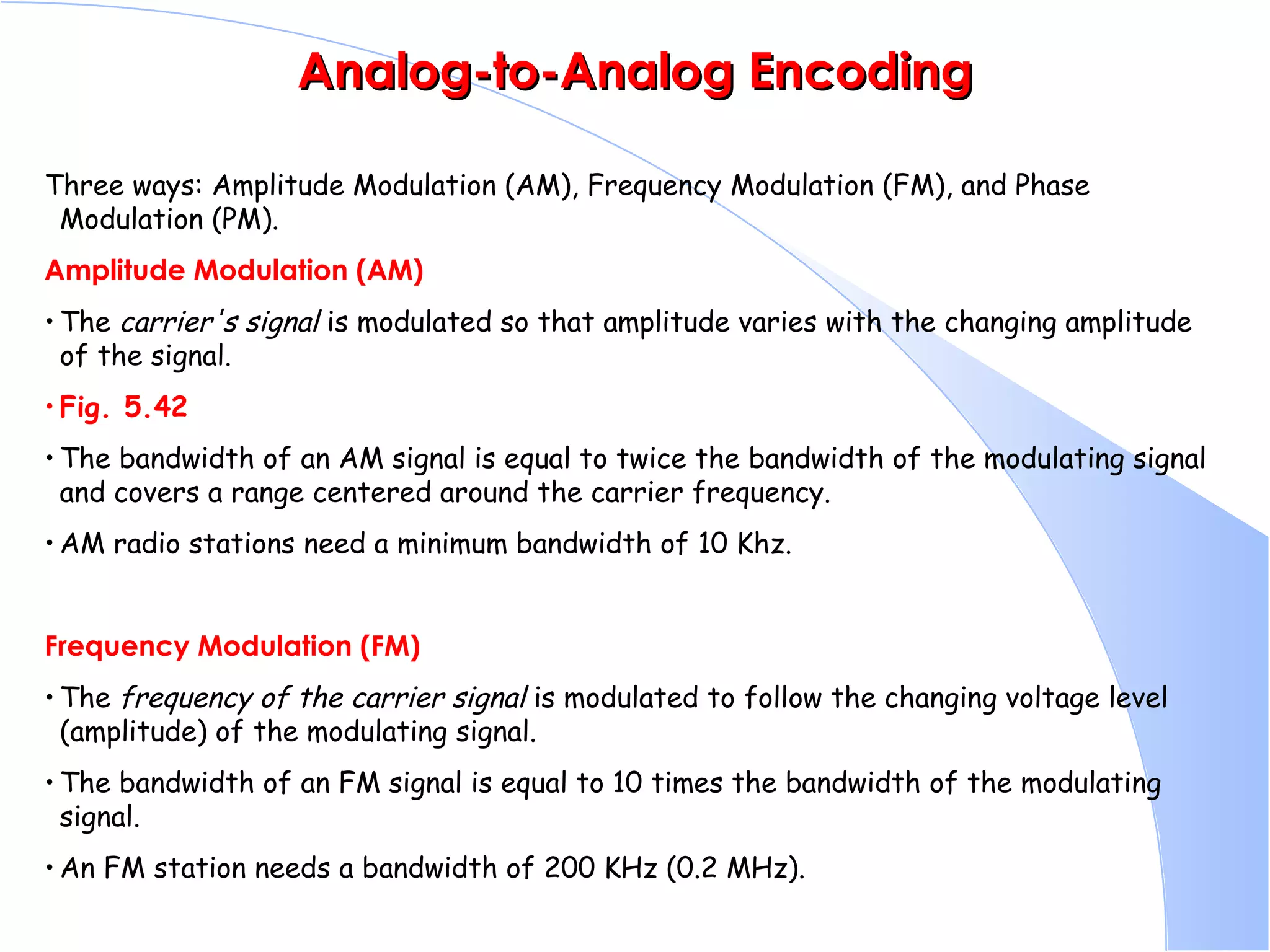
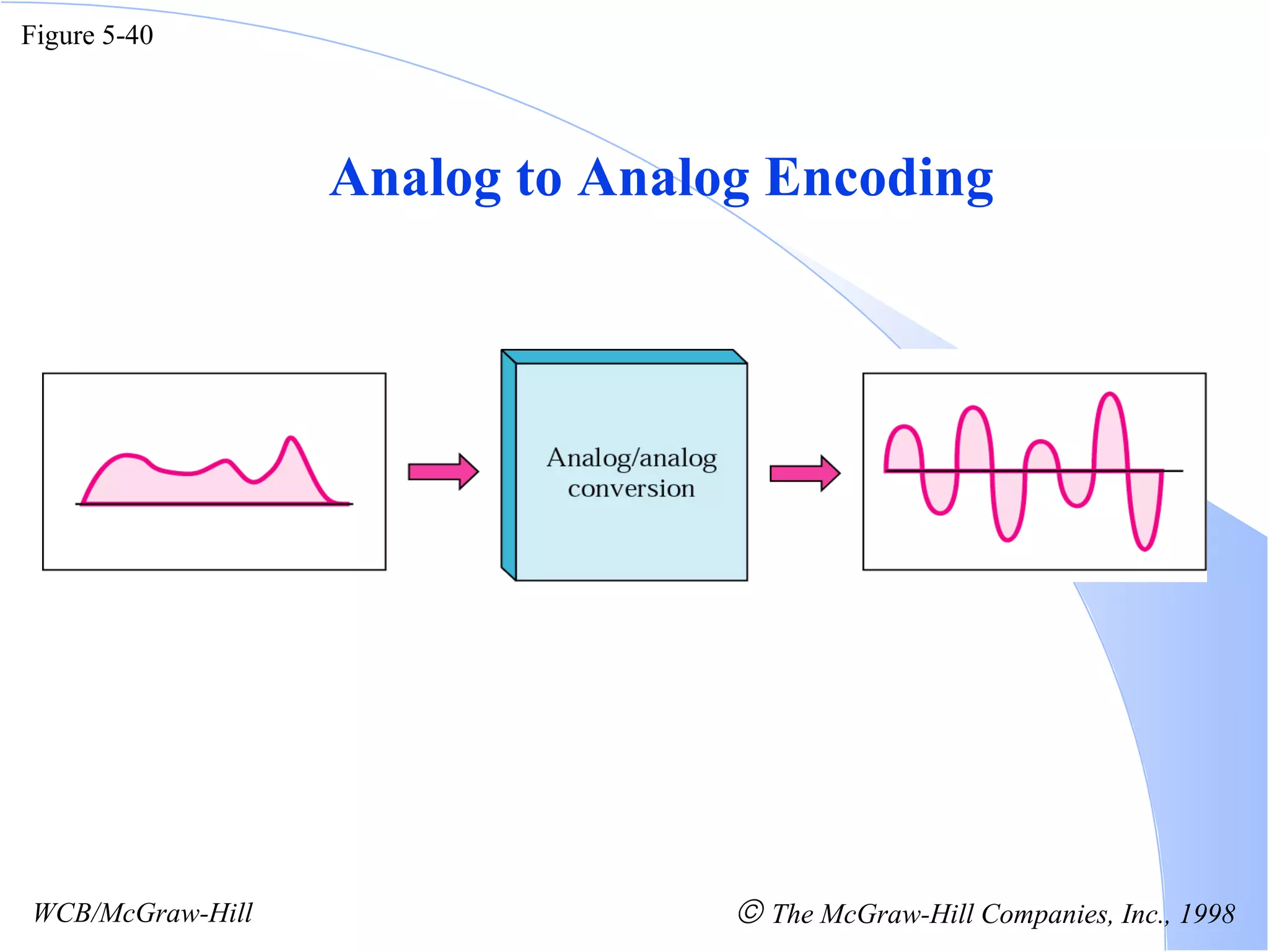
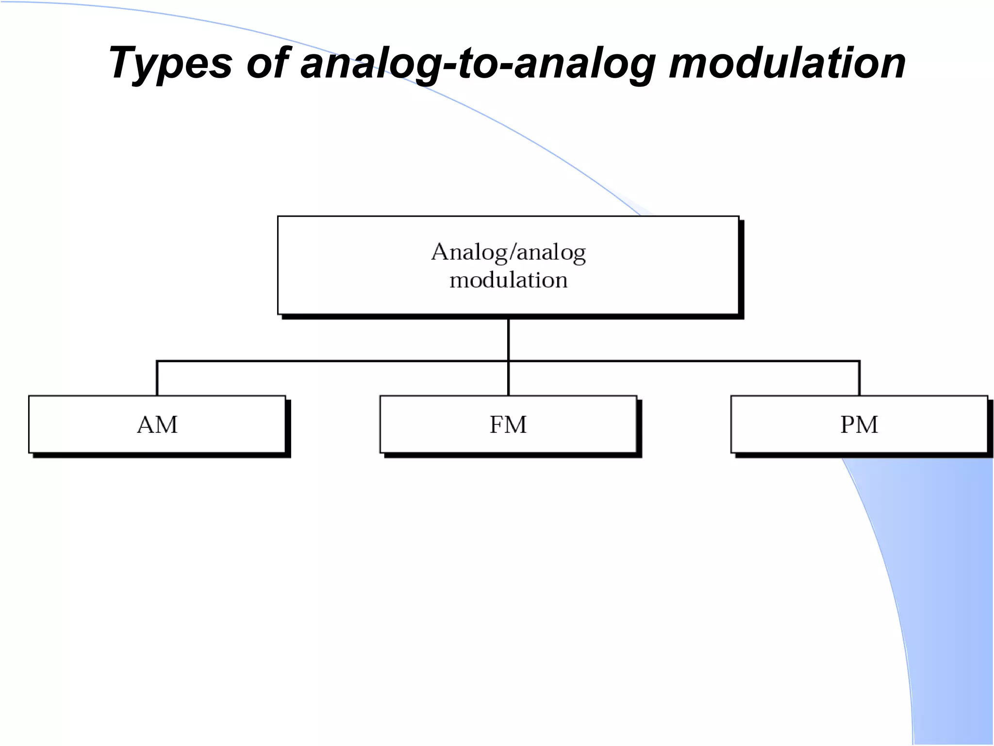
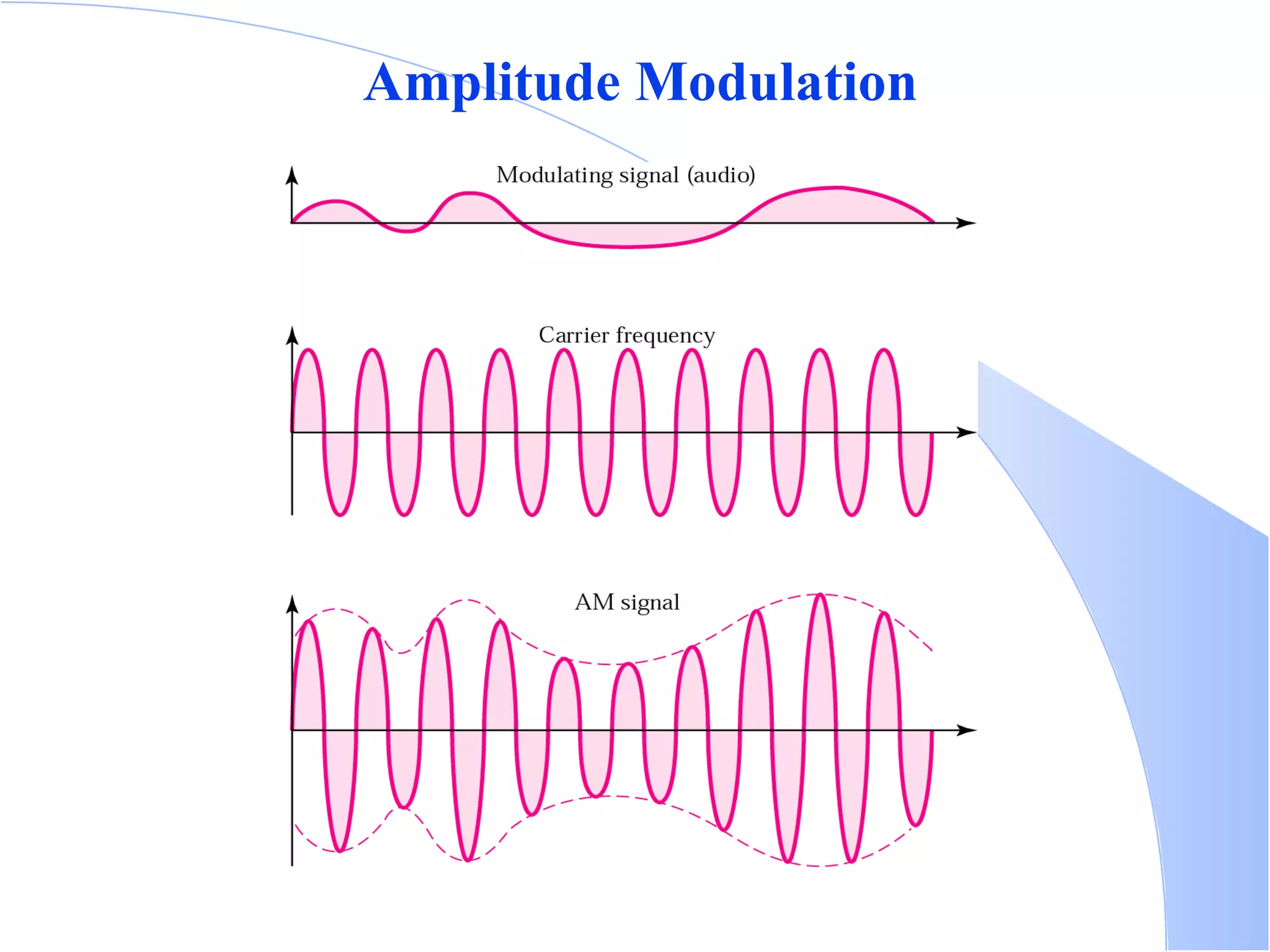
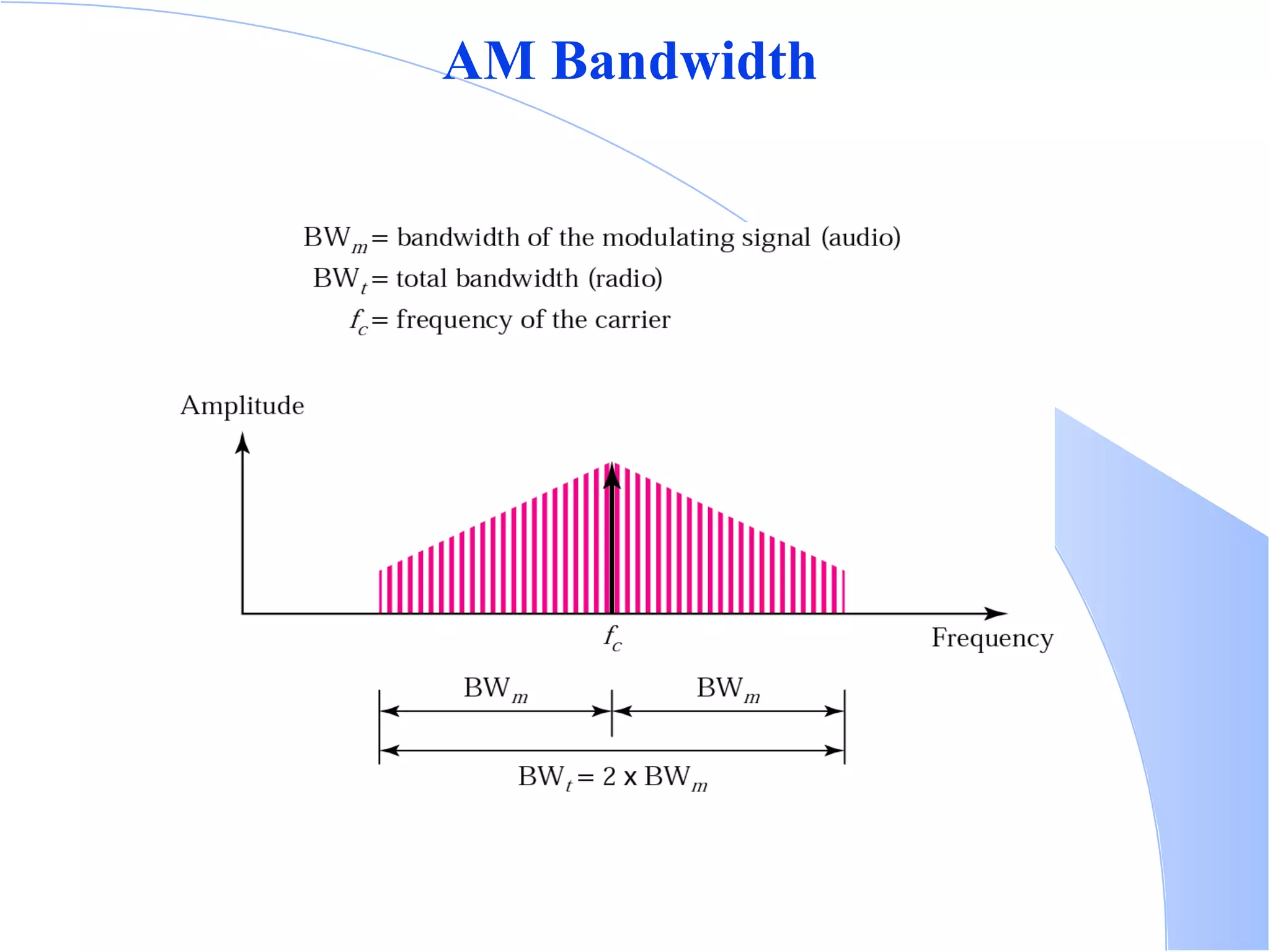

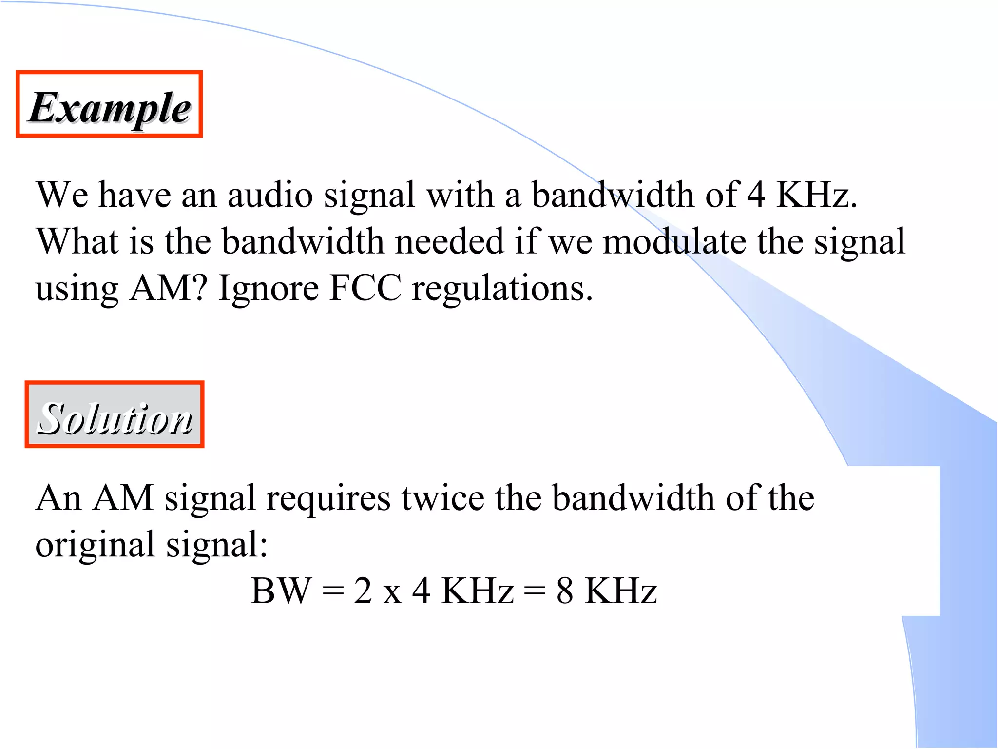
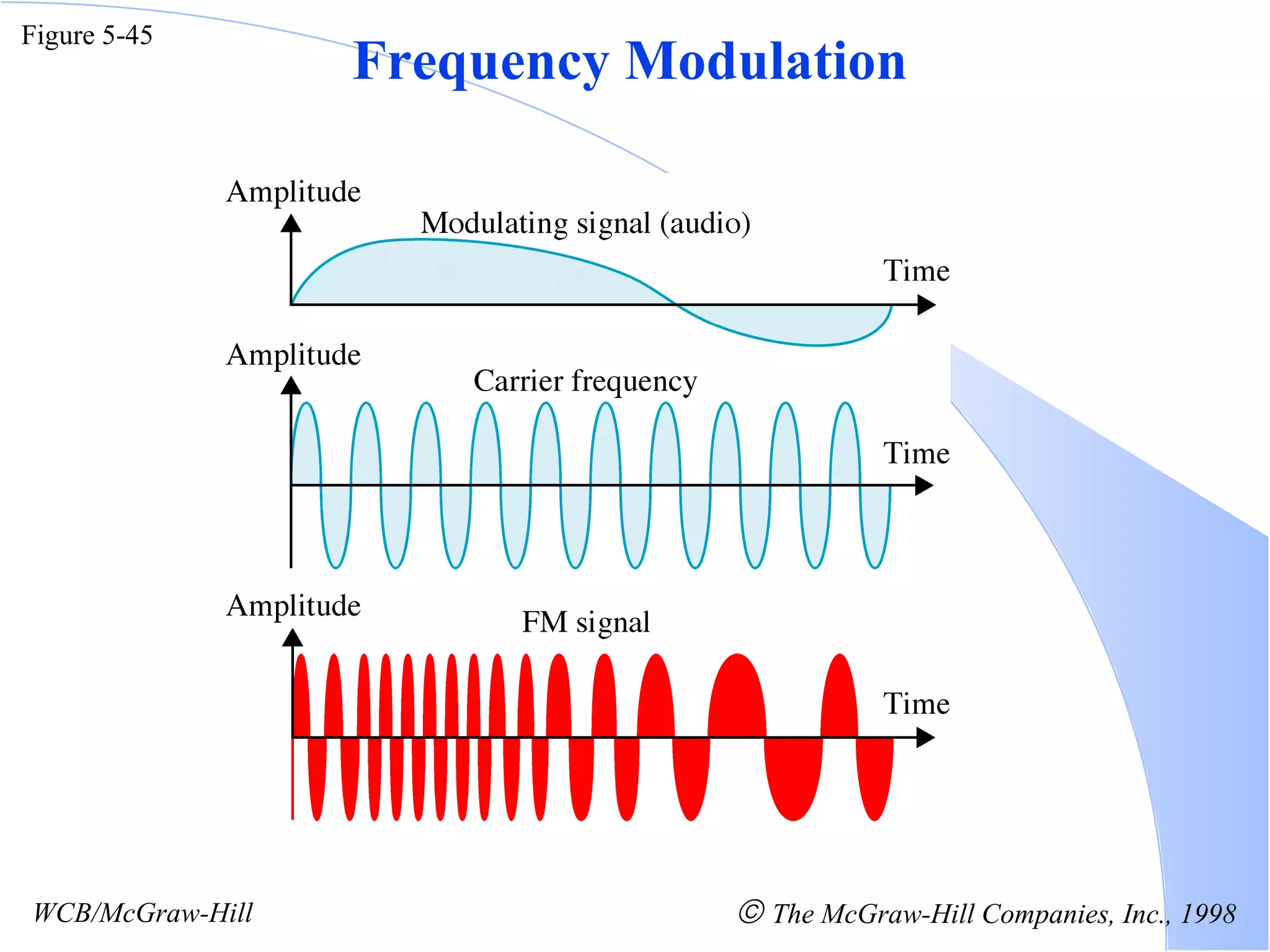


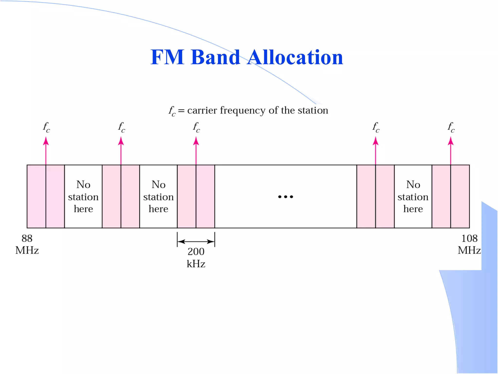

The document discusses different methods of encoding and modulating digital and analog signals for transmission. It covers digital-to-digital encoding techniques like unipolar, polar, Manchester and differential Manchester encoding. It also discusses analog-to-digital conversion techniques like PAM and PCM. Finally, it discusses analog-to-analog modulation techniques like AM, FM and PM and how they modulate parameters of a carrier signal to transmit an analog signal.


