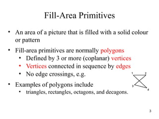
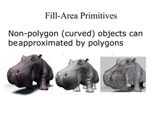
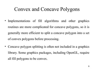
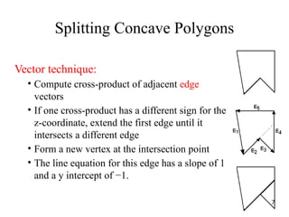
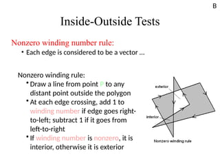
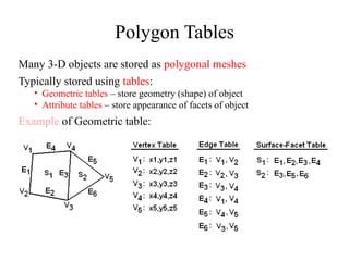
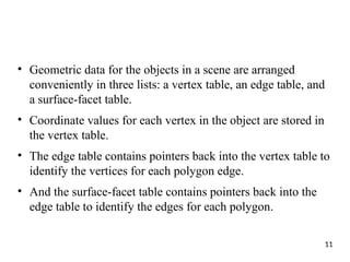
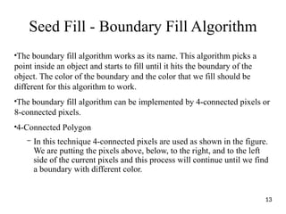
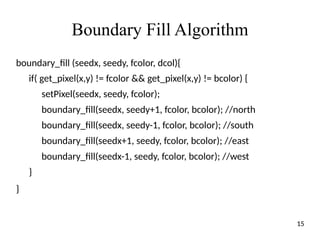
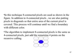
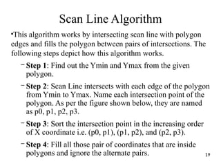
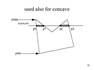
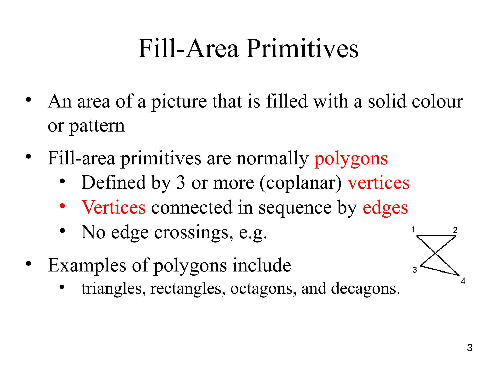
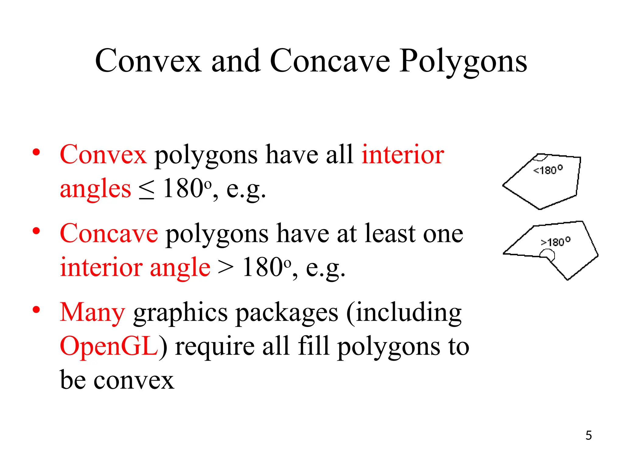
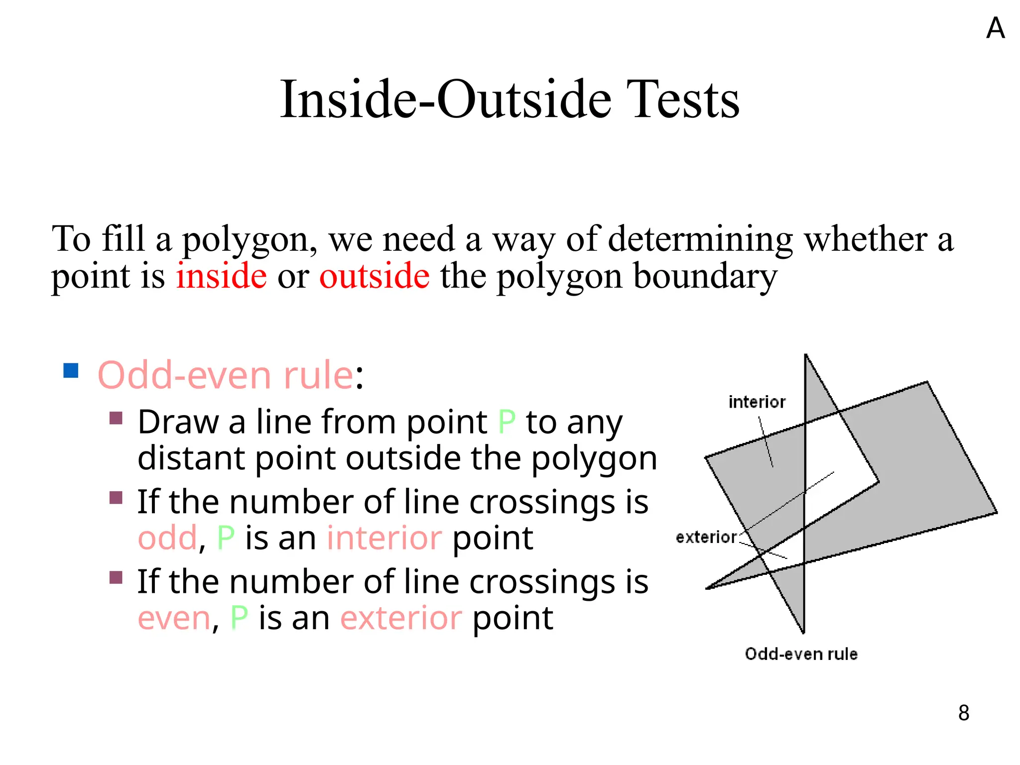
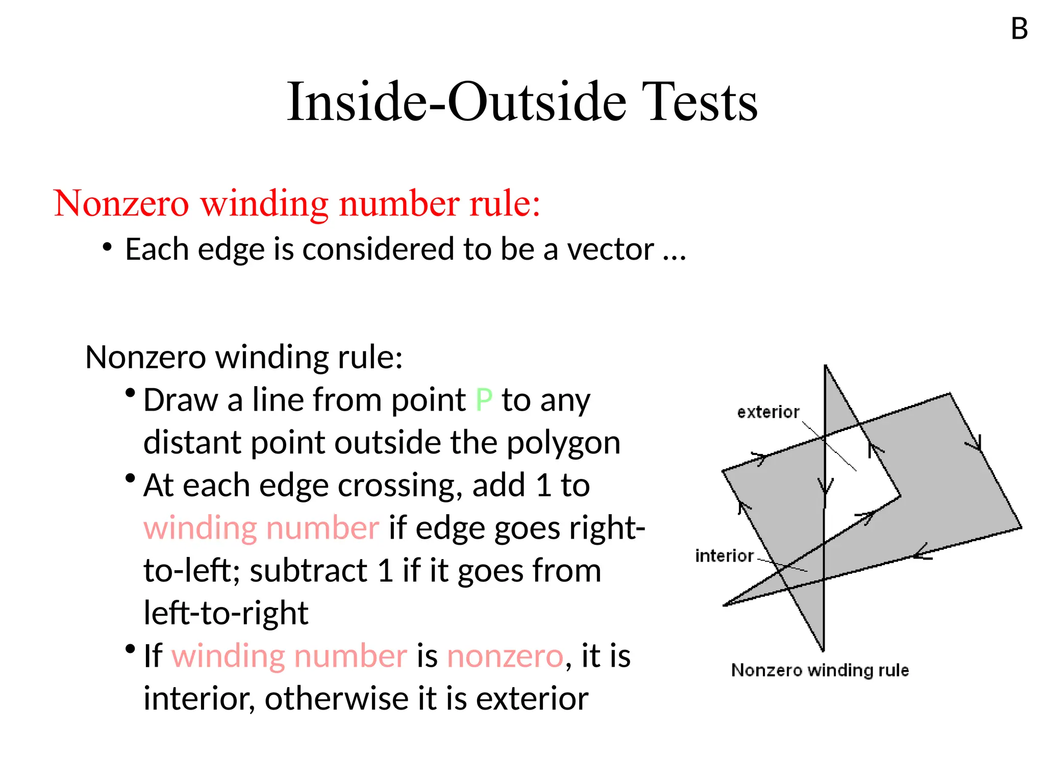
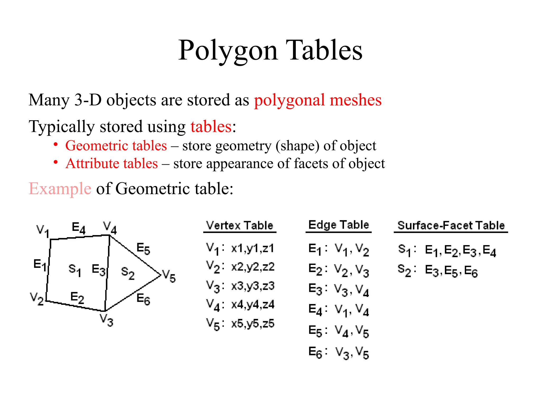
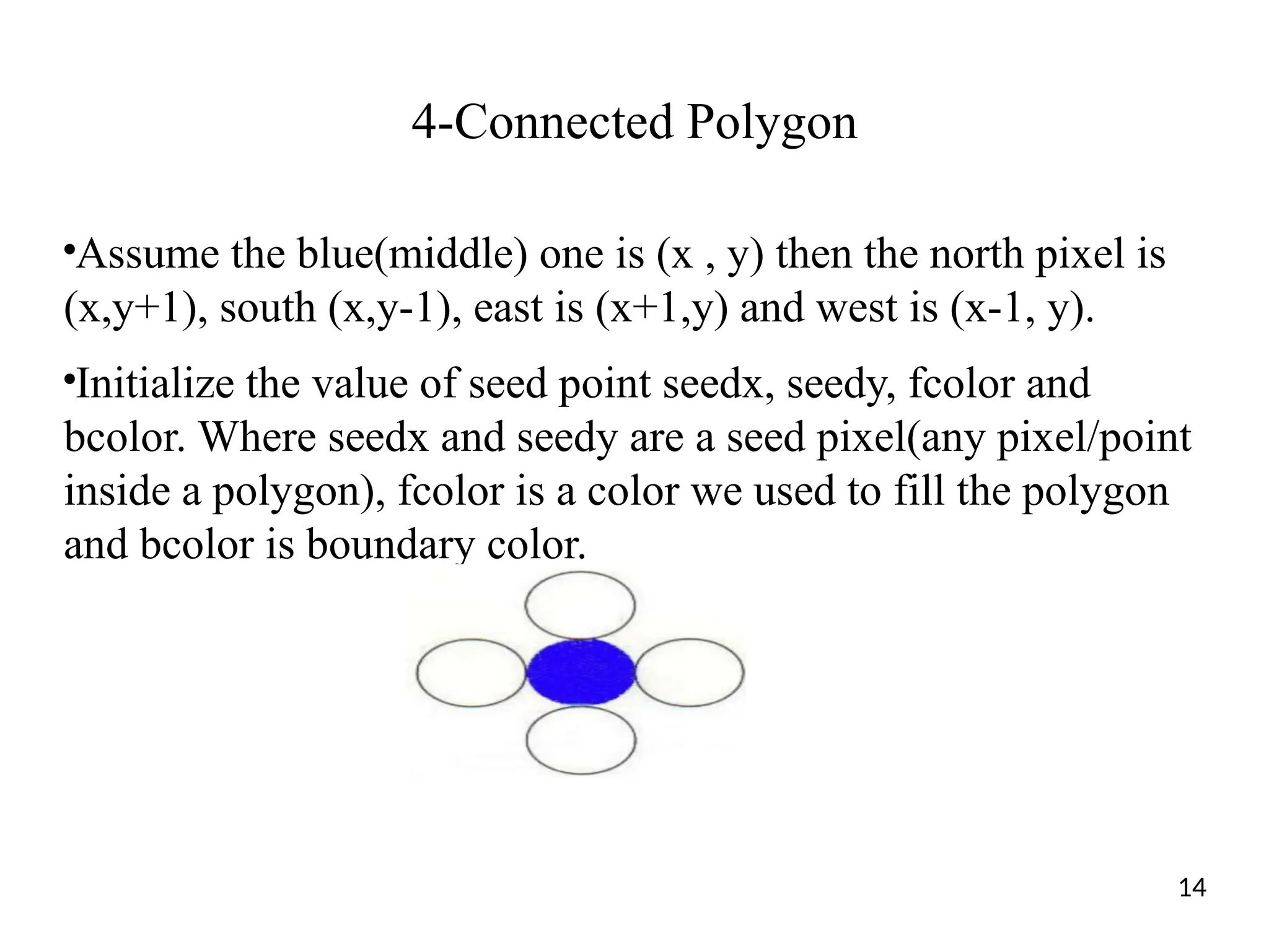
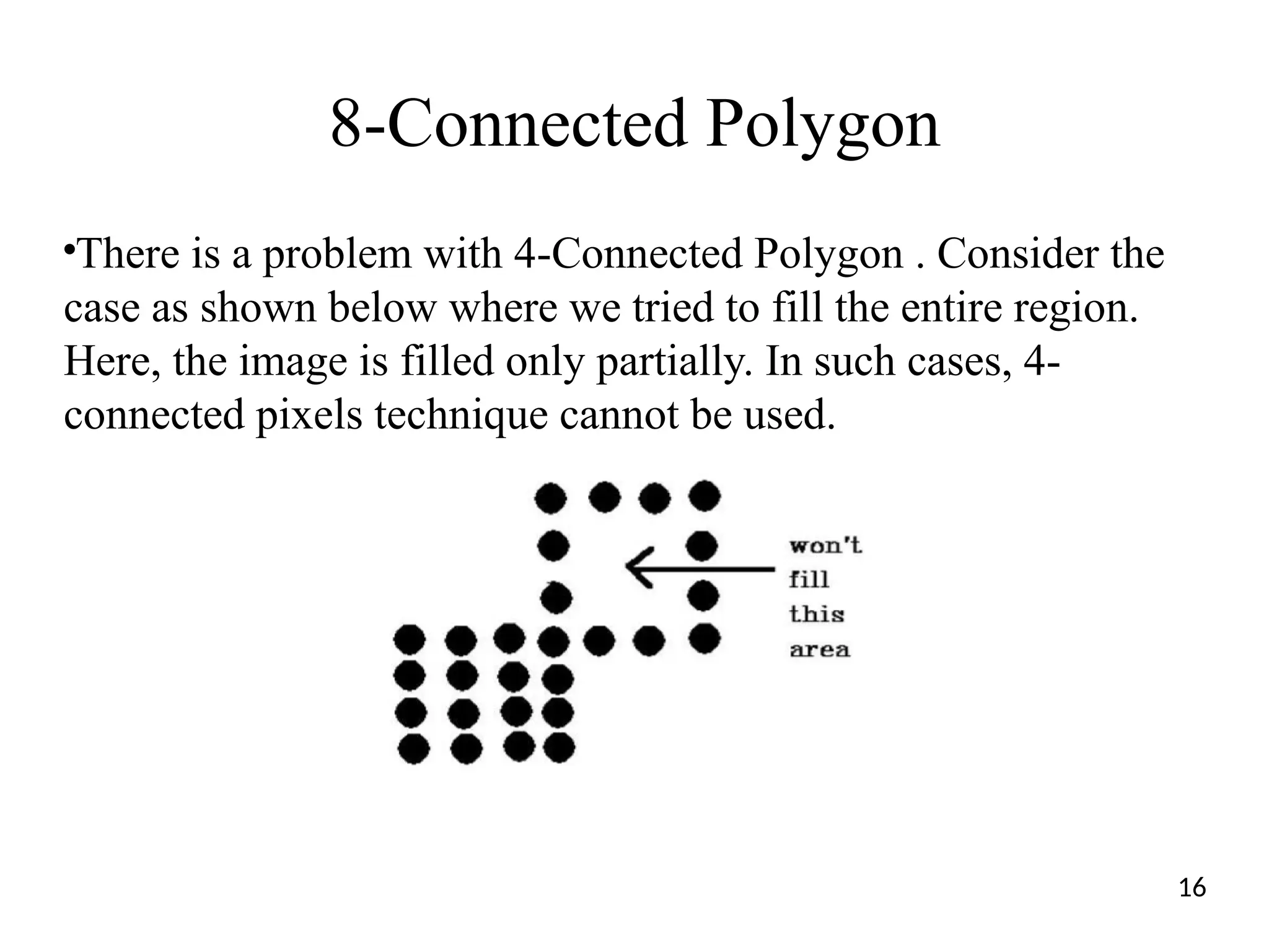
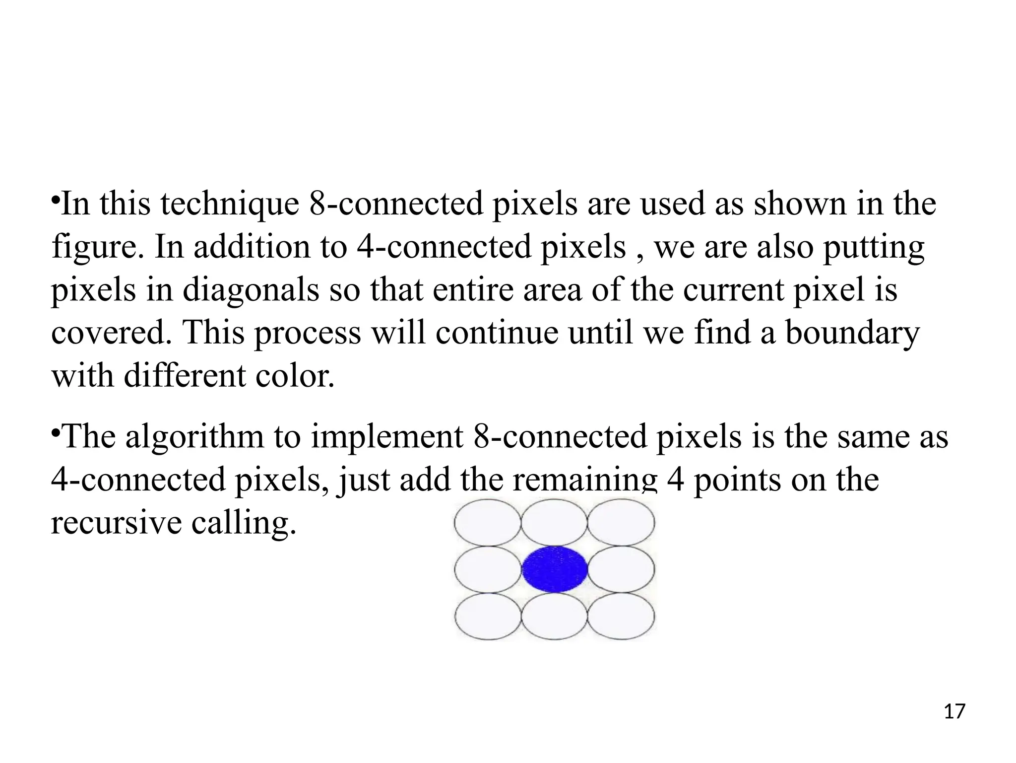
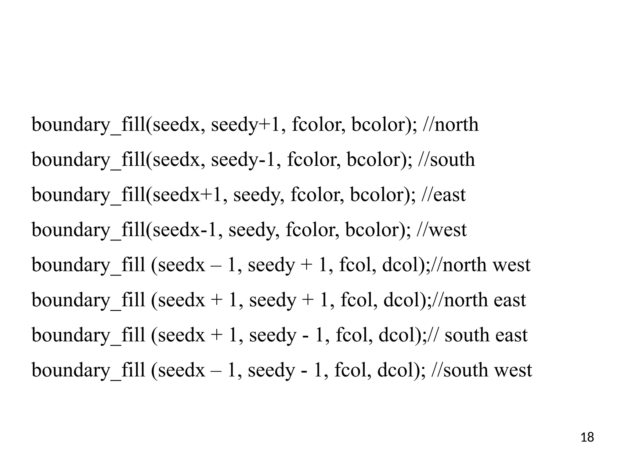
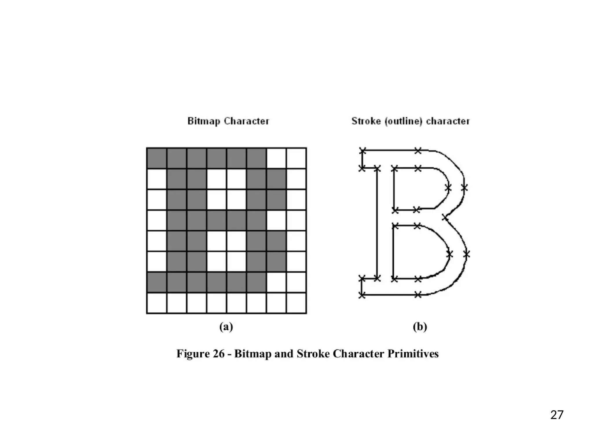
KEMBAR78
Fill area algorithm on computer graphics course | PPTX
Geometry and Line Generation
Fill Area Primitives, Curve and Character
Representation
1
Introduction
•
Previously, we have seen how we can generate
lines, circles and ellipses by using variety of
different techniques and algorithms.
•
In this section we are going to look polygon
fill area primitive, curve representation
algorithms and representation of Text and
Characters.
2
Fill-Area Primitives
• An area of a picture that is filled with a solid colour
or pattern
• Fill-area primitives are normally polygons
• Defined by 3 or more (coplanar) vertices
• Vertices connected in sequence by edges
• No edge crossings, e.g.
• Examples of polygons include
• triangles, rectangles, octagons, and decagons.
3
Fill-Area Primitives
Non-polygon (curved) objects can
beapproximated by polygons
Convex and Concave Polygons
• Convex polygons have all interior
angles ≤ 180o
, e.g.
• Concave polygons have at least one
interior angle > 180o
, e.g.
• Many graphics packages (including
OpenGL) require all fill polygons to
be convex
5
Convex and Concave Polygons
• Implementations of fill algorithms and other graphics
routines are more complicated for concave polygons, so it is
generally more efficient to split a concave polygon into a set
of convex polygons before processing.
• Concave polygon splitting is often not included in a graphics
library. Some graphics packages, including OpenGL, require
all fill polygons to be convex.
6
Splitting Concave Polygons
Vector technique:
• Compute cross-product of adjacent edge
vectors
• If one cross-product has a different sign for the
z-coordinate, extend the first edge until it
intersects a different edge
• Form a new vertex at the intersection point
• The line equation for this edge has a slope of 1
and a y intercept of −1.
7
Inside-Outside Tests
To fill a polygon, we need a way of determining whether a
point is inside or outside the polygon boundary
■ Odd-even rule:
■ Draw a line from point P to any
distant point outside the polygon
■ If the number of line crossings is
odd, P is an interior point
■ If the number of line crossings is
even, P is an exterior point
A
8
Inside-Outside Tests
Nonzero winding number rule:
• Each edge is considered to be a vector …
Nonzero winding rule:
• Draw a line from point P to any
distant point outside the polygon
• At each edge crossing, add 1 to
winding number if edge goes right-
to-left; subtract 1 if it goes from
left-to-right
• If winding number is nonzero, it is
interior, otherwise it is exterior
B
Polygon Tables
Many 3-D objects are stored as polygonal meshes
Typically stored using tables:
• Geometric tables – store geometry (shape) of object
• Attribute tables – store appearance of facets of object
Example of Geometric table:
• Geometric data for the objects in a scene are arranged
conveniently in three lists: a vertex table, an edge table, and
a surface-facet table.
• Coordinate values for each vertex in the object are stored in
the vertex table.
• The edge table contains pointers back into the vertex table to
identify the vertices for each polygon edge.
• And the surface-facet table contains pointers back into the
edge table to identify the edges for each polygon.
11
Polygon Color Filling
●
Polygon is an ordered list of vertices' for filling
polygons with particular colors, you need to determine
the pixels falling on the border of the polygon and
those which fall inside the polygon.
●
High light all the pixel inside the polygon with any
color other than background.
●
Two approaches for filling a polygon
– Seed fill
– Scan line – used to larger polygons
12
Seed Fill - Boundary Fill Algorithm
●
The boundary fill algorithm works as its name. This algorithm picks a
point inside an object and starts to fill until it hits the boundary of the
object. The color of the boundary and the color that we fill should be
different for this algorithm to work.
●
The boundary fill algorithm can be implemented by 4-connected pixels or
8-connected pixels.
●
4-Connected Polygon
– In this technique 4-connected pixels are used as shown in the figure.
We are putting the pixels above, below, to the right, and to the left
side of the current pixels and this process will continue until we find
a boundary with different color.
13
4-Connected Polygon
●
Assume the blue(middle) one is (x , y) then the north pixel is
(x,y+1), south (x,y-1), east is (x+1,y) and west is (x-1, y).
●
Initialize the value of seed point seedx, seedy, fcolor and
bcolor. Where seedx and seedy are a seed pixel(any pixel/point
inside a polygon), fcolor is a color we used to fill the polygon
and bcolor is boundary color.
14
Boundary Fill Algorithm
boundary_fill (seedx, seedy, fcolor, dcol){
if( get_pixel(x,y) != fcolor && get_pixel(x,y) != bcolor) {
setPixel(seedx, seedy, fcolor);
boundary_fill(seedx, seedy+1, fcolor, bcolor); //north
boundary_fill(seedx, seedy-1, fcolor, bcolor); //south
boundary_fill(seedx+1, seedy, fcolor, bcolor); //east
boundary_fill(seedx-1, seedy, fcolor, bcolor); //west
}
}
15
8-Connected Polygon
●
There is a problem with 4-Connected Polygon . Consider the
case as shown below where we tried to fill the entire region.
Here, the image is filled only partially. In such cases, 4-
connected pixels technique cannot be used.
16
●
In this technique 8-connected pixels are used as shown in the
figure. In addition to 4-connected pixels , we are also putting
pixels in diagonals so that entire area of the current pixel is
covered. This process will continue until we find a boundary
with different color.
●
The algorithm to implement 8-connected pixels is the same as
4-connected pixels, just add the remaining 4 points on the
recursive calling.
17
boundary_fill(seedx, seedy+1, fcolor, bcolor); //north
boundary_fill(seedx, seedy-1, fcolor, bcolor); //south
boundary_fill(seedx+1, seedy, fcolor, bcolor); //east
boundary_fill(seedx-1, seedy, fcolor, bcolor); //west
boundary_fill (seedx – 1, seedy + 1, fcol, dcol);//north west
boundary_fill (seedx + 1, seedy + 1, fcol, dcol);//north east
boundary_fill (seedx + 1, seedy - 1, fcol, dcol);// south east
boundary_fill (seedx – 1, seedy - 1, fcol, dcol); //south west
18
Scan Line Algorithm
●
This algorithm works by intersecting scan line with polygon
edges and fills the polygon between pairs of intersections. The
following steps depict how this algorithm works.
– Step 1: Find out the Ymin and Ymax from the given
polygon.
– Step 2: Scan Line intersects with each edge of the polygon
from Ymin to Ymax. Name each intersection point of the
polygon. As per the figure shown below, they are named
as p0, p1, p2, p3.
– Step 3: Sort the intersection point in the increasing order
of X coordinate i.e. (p0, p1), (p1, p2), and (p2, p3).
– Step 4: Fill all those pair of coordinates that are inside
polygons and ignore the alternate pairs. 19
used also for concave
20
Text and Characters
●
OpenGL on its own does not contain any routines
dedicated to drawing text characters.
●
However, the glut library does contain two different
routines for drawing individual characters (not strings).
●
Before drawing any character, we must first set the
raster position, i.e. where will the character be drawn.
21
Raster position-glRasterPos2i
●
We need to do this only once for each sequence of characters.
After each character is drawn the raster position will be
automatically updated ready for drawing the next character.
●
To set the raster position we use the glRasterPos2i routine.
●
Next, we can display our characters. The routine we use to do
this will depend on whether we want to draw a bitmap or stroke
character.
22
BitMap
●
For bitmap characters we can write, for example,
glutBitmapCharacter(GLUT_BITMAP_9_BY_15, ‘a’);
•
This will draw the character ‘a’ in a monospace bitmap font
with width 9 and height 15 pixels.
There are a number of alternative symbolic constants that we
can use in place of GLUT_BITMAP_9_BY_15 to specify
different types of bitmap font. For example,
GLUT_BITMAP_8_BY_13, GLUT_BITMAP_9_BY_15
●
Using a bitmap representation (or font), characters are stored
as a grid of pixel values (see Figure 26(a)).
23
●
Bitmap is a simple representation that allows fast rendering of the
character. However, it is not easily scalable:
●
if we want to draw a larger version of a character defined using a
bitmap we will get an aliasing effect (the edges of the characters will
appear jagged due to the low resolution). Similarly, we cannot easily
generate bold or italic versions of the character.
●
For this reason, when using bitmap fonts we normally need to store
multiple fonts to represent the characters in different sizes/styles etc.
●
GLUT_BITMAP_TIMES_ROMAN_10
●
GLUT_BITMAP_HELVETICA_10 24
Stroke
●
An alternative representation to bitmaps is the stroke, or
outline, representation (see Figure 26(b)).
●
Using stroke representations characters are stored using line or
curve primitives. To draw the character we must convert these
primitives into pixel values on the display.
●
They are much more easily scalable: to generate a larger
version of the character we just multiply the coordinates of the
line/curve primitives by some scaling factor. Bold and italic
characters can be generated using a similar approach.
●
The disadvantage of stroke fonts is that they take longer time
to draw than bitmap fonts.
25
●
We can use stroke fonts using the glutStrokeCharacter
routine. For example,
glutStrokeCharacter(GLUT_STROKE_ROMAN, ‘a’);
●
This will draw the letter ‘a’ using the Roman stroke font,
which is a proportional font. We can specify a monospace
stroke font using the following symbolic constant:
– GLUT_STROKE_MONO_ROMAN
●
The characters can be scaled using glScalef(0.1f, 0.1f,
1.0f), but you can adjust the scale factors based on your
requirements.
26
27
End of Chapter Three

Fill area algorithm on computer graphics course

  • 1.
    Geometry and LineGeneration Fill Area Primitives, Curve and Character Representation 1
  • 2.
    Introduction • Previously, we haveseen how we can generate lines, circles and ellipses by using variety of different techniques and algorithms. • In this section we are going to look polygon fill area primitive, curve representation algorithms and representation of Text and Characters. 2
  • 3.
    Fill-Area Primitives • Anarea of a picture that is filled with a solid colour or pattern • Fill-area primitives are normally polygons • Defined by 3 or more (coplanar) vertices • Vertices connected in sequence by edges • No edge crossings, e.g. • Examples of polygons include • triangles, rectangles, octagons, and decagons. 3
  • 4.
    Fill-Area Primitives Non-polygon (curved)objects can beapproximated by polygons
  • 5.
    Convex and ConcavePolygons • Convex polygons have all interior angles ≤ 180o , e.g. • Concave polygons have at least one interior angle > 180o , e.g. • Many graphics packages (including OpenGL) require all fill polygons to be convex 5
  • 6.
    Convex and ConcavePolygons • Implementations of fill algorithms and other graphics routines are more complicated for concave polygons, so it is generally more efficient to split a concave polygon into a set of convex polygons before processing. • Concave polygon splitting is often not included in a graphics library. Some graphics packages, including OpenGL, require all fill polygons to be convex. 6
  • 7.
    Splitting Concave Polygons Vectortechnique: • Compute cross-product of adjacent edge vectors • If one cross-product has a different sign for the z-coordinate, extend the first edge until it intersects a different edge • Form a new vertex at the intersection point • The line equation for this edge has a slope of 1 and a y intercept of −1. 7
  • 8.
    Inside-Outside Tests To filla polygon, we need a way of determining whether a point is inside or outside the polygon boundary ■ Odd-even rule: ■ Draw a line from point P to any distant point outside the polygon ■ If the number of line crossings is odd, P is an interior point ■ If the number of line crossings is even, P is an exterior point A 8
  • 9.
    Inside-Outside Tests Nonzero windingnumber rule: • Each edge is considered to be a vector … Nonzero winding rule: • Draw a line from point P to any distant point outside the polygon • At each edge crossing, add 1 to winding number if edge goes right- to-left; subtract 1 if it goes from left-to-right • If winding number is nonzero, it is interior, otherwise it is exterior B
  • 10.
    Polygon Tables Many 3-Dobjects are stored as polygonal meshes Typically stored using tables: • Geometric tables – store geometry (shape) of object • Attribute tables – store appearance of facets of object Example of Geometric table:
  • 11.
    • Geometric datafor the objects in a scene are arranged conveniently in three lists: a vertex table, an edge table, and a surface-facet table. • Coordinate values for each vertex in the object are stored in the vertex table. • The edge table contains pointers back into the vertex table to identify the vertices for each polygon edge. • And the surface-facet table contains pointers back into the edge table to identify the edges for each polygon. 11
  • 12.
    Polygon Color Filling ● Polygonis an ordered list of vertices' for filling polygons with particular colors, you need to determine the pixels falling on the border of the polygon and those which fall inside the polygon. ● High light all the pixel inside the polygon with any color other than background. ● Two approaches for filling a polygon – Seed fill – Scan line – used to larger polygons 12
  • 13.
    Seed Fill -Boundary Fill Algorithm ● The boundary fill algorithm works as its name. This algorithm picks a point inside an object and starts to fill until it hits the boundary of the object. The color of the boundary and the color that we fill should be different for this algorithm to work. ● The boundary fill algorithm can be implemented by 4-connected pixels or 8-connected pixels. ● 4-Connected Polygon – In this technique 4-connected pixels are used as shown in the figure. We are putting the pixels above, below, to the right, and to the left side of the current pixels and this process will continue until we find a boundary with different color. 13
  • 14.
    4-Connected Polygon ● Assume theblue(middle) one is (x , y) then the north pixel is (x,y+1), south (x,y-1), east is (x+1,y) and west is (x-1, y). ● Initialize the value of seed point seedx, seedy, fcolor and bcolor. Where seedx and seedy are a seed pixel(any pixel/point inside a polygon), fcolor is a color we used to fill the polygon and bcolor is boundary color. 14
  • 15.
    Boundary Fill Algorithm boundary_fill(seedx, seedy, fcolor, dcol){ if( get_pixel(x,y) != fcolor && get_pixel(x,y) != bcolor) { setPixel(seedx, seedy, fcolor); boundary_fill(seedx, seedy+1, fcolor, bcolor); //north boundary_fill(seedx, seedy-1, fcolor, bcolor); //south boundary_fill(seedx+1, seedy, fcolor, bcolor); //east boundary_fill(seedx-1, seedy, fcolor, bcolor); //west } } 15
  • 16.
    8-Connected Polygon ● There isa problem with 4-Connected Polygon . Consider the case as shown below where we tried to fill the entire region. Here, the image is filled only partially. In such cases, 4- connected pixels technique cannot be used. 16
  • 17.
    ● In this technique8-connected pixels are used as shown in the figure. In addition to 4-connected pixels , we are also putting pixels in diagonals so that entire area of the current pixel is covered. This process will continue until we find a boundary with different color. ● The algorithm to implement 8-connected pixels is the same as 4-connected pixels, just add the remaining 4 points on the recursive calling. 17
  • 18.
    boundary_fill(seedx, seedy+1, fcolor,bcolor); //north boundary_fill(seedx, seedy-1, fcolor, bcolor); //south boundary_fill(seedx+1, seedy, fcolor, bcolor); //east boundary_fill(seedx-1, seedy, fcolor, bcolor); //west boundary_fill (seedx – 1, seedy + 1, fcol, dcol);//north west boundary_fill (seedx + 1, seedy + 1, fcol, dcol);//north east boundary_fill (seedx + 1, seedy - 1, fcol, dcol);// south east boundary_fill (seedx – 1, seedy - 1, fcol, dcol); //south west 18
  • 19.
    Scan Line Algorithm ● Thisalgorithm works by intersecting scan line with polygon edges and fills the polygon between pairs of intersections. The following steps depict how this algorithm works. – Step 1: Find out the Ymin and Ymax from the given polygon. – Step 2: Scan Line intersects with each edge of the polygon from Ymin to Ymax. Name each intersection point of the polygon. As per the figure shown below, they are named as p0, p1, p2, p3. – Step 3: Sort the intersection point in the increasing order of X coordinate i.e. (p0, p1), (p1, p2), and (p2, p3). – Step 4: Fill all those pair of coordinates that are inside polygons and ignore the alternate pairs. 19
  • 20.
    used also forconcave 20
  • 21.
    Text and Characters ● OpenGLon its own does not contain any routines dedicated to drawing text characters. ● However, the glut library does contain two different routines for drawing individual characters (not strings). ● Before drawing any character, we must first set the raster position, i.e. where will the character be drawn. 21
  • 22.
    Raster position-glRasterPos2i ● We needto do this only once for each sequence of characters. After each character is drawn the raster position will be automatically updated ready for drawing the next character. ● To set the raster position we use the glRasterPos2i routine. ● Next, we can display our characters. The routine we use to do this will depend on whether we want to draw a bitmap or stroke character. 22
  • 23.
    BitMap ● For bitmap characterswe can write, for example, glutBitmapCharacter(GLUT_BITMAP_9_BY_15, ‘a’); • This will draw the character ‘a’ in a monospace bitmap font with width 9 and height 15 pixels. There are a number of alternative symbolic constants that we can use in place of GLUT_BITMAP_9_BY_15 to specify different types of bitmap font. For example, GLUT_BITMAP_8_BY_13, GLUT_BITMAP_9_BY_15 ● Using a bitmap representation (or font), characters are stored as a grid of pixel values (see Figure 26(a)). 23
  • 24.
    ● Bitmap is asimple representation that allows fast rendering of the character. However, it is not easily scalable: ● if we want to draw a larger version of a character defined using a bitmap we will get an aliasing effect (the edges of the characters will appear jagged due to the low resolution). Similarly, we cannot easily generate bold or italic versions of the character. ● For this reason, when using bitmap fonts we normally need to store multiple fonts to represent the characters in different sizes/styles etc. ● GLUT_BITMAP_TIMES_ROMAN_10 ● GLUT_BITMAP_HELVETICA_10 24
  • 25.
    Stroke ● An alternative representationto bitmaps is the stroke, or outline, representation (see Figure 26(b)). ● Using stroke representations characters are stored using line or curve primitives. To draw the character we must convert these primitives into pixel values on the display. ● They are much more easily scalable: to generate a larger version of the character we just multiply the coordinates of the line/curve primitives by some scaling factor. Bold and italic characters can be generated using a similar approach. ● The disadvantage of stroke fonts is that they take longer time to draw than bitmap fonts. 25
  • 26.
    ● We can usestroke fonts using the glutStrokeCharacter routine. For example, glutStrokeCharacter(GLUT_STROKE_ROMAN, ‘a’); ● This will draw the letter ‘a’ using the Roman stroke font, which is a proportional font. We can specify a monospace stroke font using the following symbolic constant: – GLUT_STROKE_MONO_ROMAN ● The characters can be scaled using glScalef(0.1f, 0.1f, 1.0f), but you can adjust the scale factors based on your requirements. 26
  • 27.
  • 28.