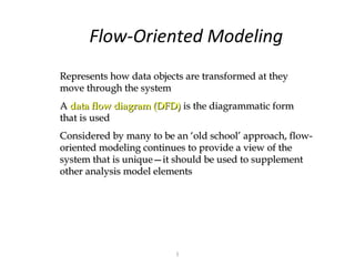
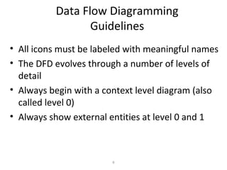
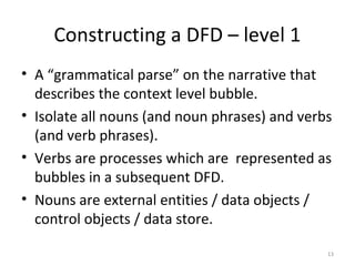
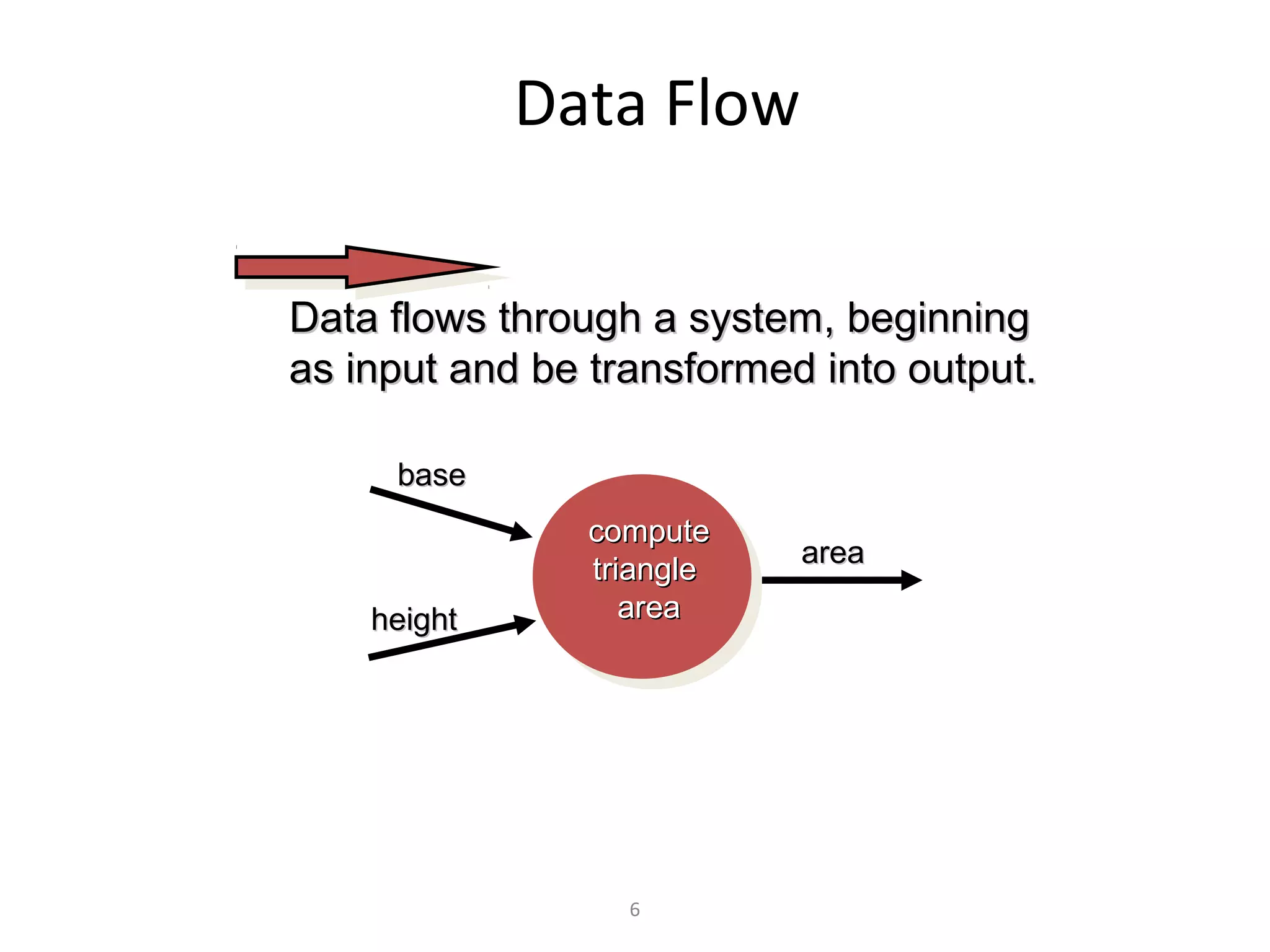
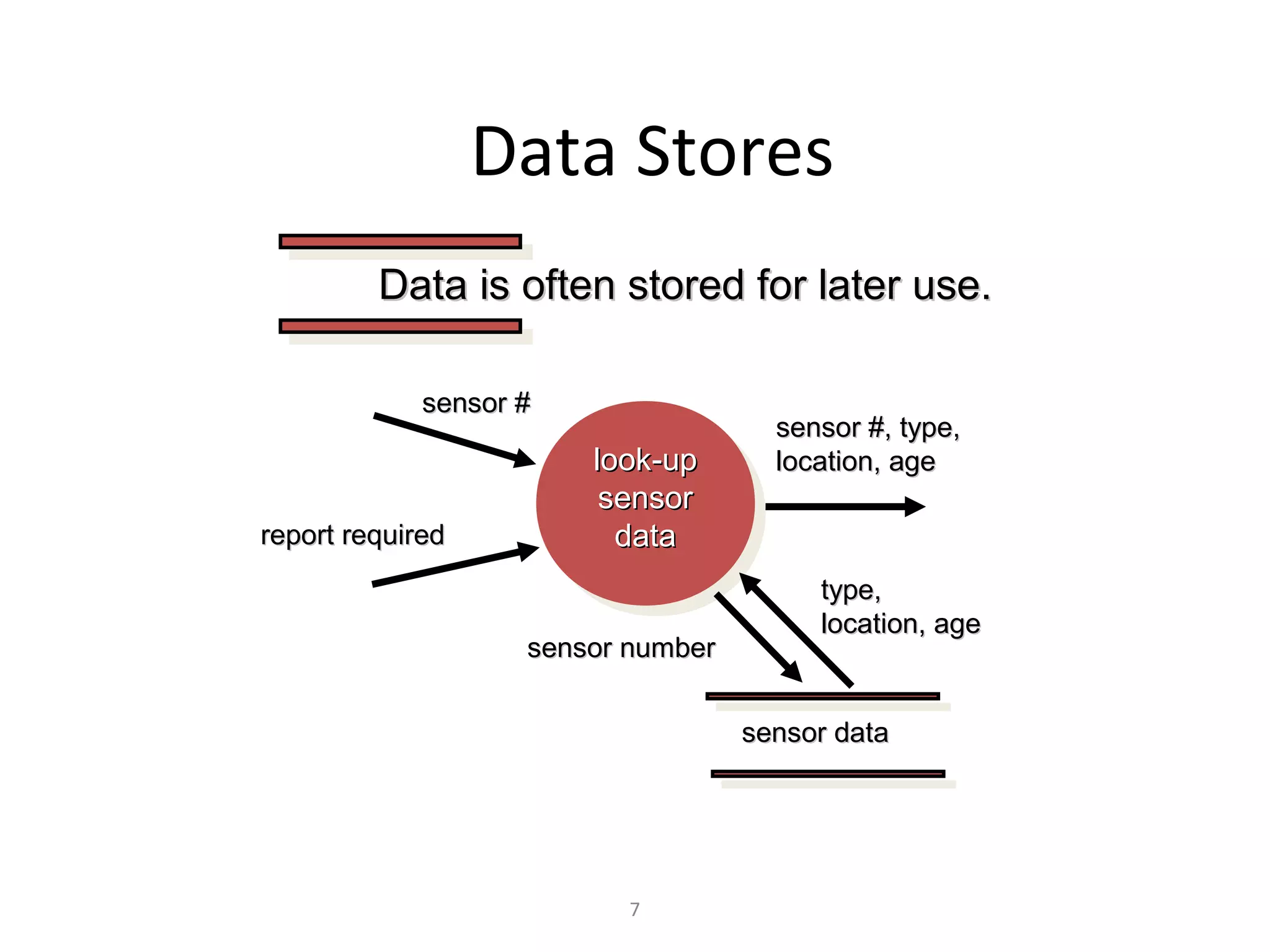
KEMBAR78
Flow oriented modeling | PPT
Flow-Oriented Modeling
Represents how data objects are transformed at they
move through the system
A data flow diagram (DFD) is the diagrammatic form
that is used
Considered by many to be an ‘old school’ approach, flow-
oriented modeling continues to provide a view of the
system that is unique—it should be used to supplement
other analysis model elements


                         1
The Flow Model
Every computer-based system is an
information transform ....


              computer
input          based        output
               system


                2
Flow Modeling Notation

         external entity


         process


             data flow


         data store


         3
External Entity
 A producer or consumer of data


Examples: a person, a device, a sensor

Another example: computer-based
system

 Data must always originate somewhere
 and must always be sent to something


                  4
Process
  A data transformer (changes input
  to output)

Examples: compute taxes, determine area,
format report, display graph

 Data must always be processed in some
 way to achieve system function


                   5
Data Flow

Data flows through a system, beginning
as input and be transformed into output.

     base
               compute
                           area
               triangle
    height        area


                  6
Data Stores
         Data is often stored for later use.

             sensor #
                                      sensor #, type,
                        look-up       location, age
                         sensor
report required           data
                                         type,
                                         location, age
                    sensor number


                                    sensor data


                           7
Data Flow Diagramming
                 Guidelines
• All icons must be labeled with meaningful names
• The DFD evolves through a number of levels of
  detail
• Always begin with a context level diagram (also
  called level 0)
• Always show external entities at level 0 and 1


                        8
• The level 0 data flow diagram should depict the
  software/system as a single bubble
• Primary input and output should be carefully
  noted
• Refinement should begin by isolating candidate
  processes, data objects, and data stores to be
  represented at the next level
• All arrows and bubbles should be labeled with
  meaningful names
• Information flow continuity must be maintained
  from level to level
• One bubble at a time should be refined
                                                    9
Constructing a DFD – level 0

• Review the data model to isolate data
  objects and use a grammatical parse to
  determine “operations”
• Determine external entities (producers
  and consumers of data)
• Create a level 0 DFD


                   10
11
12
Constructing a DFD – level 1
• A “grammatical parse” on the narrative that
  describes the context level bubble.
• Isolate all nouns (and noun phrases) and verbs
  (and verb phrases).
• Verbs are processes which are represented as
  bubbles in a subsequent DFD.
• Nouns are external entities / data objects /
  control objects / data store.

                                               13
14
Constructing a DFD – level 2
• Refines the monitor sensors process


                                        15
16
PSPEC
•   The process transform performs password validation at the control panel
    for the SafeHome security function.
•   Process password receives a four-digit password from the interact with
    user function.
•   The password is first compared to the master password stored within the
    system.
•   If the master password matches , [valid id message = true] is passed to the
    message and status display function.
•   If the master password does not match , the four digits are compared to a
    table of secondary passwords (they may be assigned to house guests
    and/or workers who require entry to the home when the owner is not
    present).
•   If the password matches an entry with the table, [valid id message = true]
    is passed to the message and status display function.
•   If there is no match, [valid id message = false] is passed to the message
    and status display function.

                                                                             17

Flow oriented modeling

  • 1.
    Flow-Oriented Modeling Represents howdata objects are transformed at they move through the system A data flow diagram (DFD) is the diagrammatic form that is used Considered by many to be an ‘old school’ approach, flow- oriented modeling continues to provide a view of the system that is unique—it should be used to supplement other analysis model elements 1
  • 2.
    The Flow Model Everycomputer-based system is an information transform .... computer input based output system 2
  • 3.
    Flow Modeling Notation external entity process data flow data store 3
  • 4.
    External Entity Aproducer or consumer of data Examples: a person, a device, a sensor Another example: computer-based system Data must always originate somewhere and must always be sent to something 4
  • 5.
    Process Adata transformer (changes input to output) Examples: compute taxes, determine area, format report, display graph Data must always be processed in some way to achieve system function 5
  • 6.
    Data Flow Data flowsthrough a system, beginning as input and be transformed into output. base compute area triangle height area 6
  • 7.
    Data Stores Data is often stored for later use. sensor # sensor #, type, look-up location, age sensor report required data type, location, age sensor number sensor data 7
  • 8.
    Data Flow Diagramming Guidelines • All icons must be labeled with meaningful names • The DFD evolves through a number of levels of detail • Always begin with a context level diagram (also called level 0) • Always show external entities at level 0 and 1 8
  • 9.
    • The level0 data flow diagram should depict the software/system as a single bubble • Primary input and output should be carefully noted • Refinement should begin by isolating candidate processes, data objects, and data stores to be represented at the next level • All arrows and bubbles should be labeled with meaningful names • Information flow continuity must be maintained from level to level • One bubble at a time should be refined 9
  • 10.
    Constructing a DFD– level 0 • Review the data model to isolate data objects and use a grammatical parse to determine “operations” • Determine external entities (producers and consumers of data) • Create a level 0 DFD 10
  • 11.
  • 12.
  • 13.
    Constructing a DFD– level 1 • A “grammatical parse” on the narrative that describes the context level bubble. • Isolate all nouns (and noun phrases) and verbs (and verb phrases). • Verbs are processes which are represented as bubbles in a subsequent DFD. • Nouns are external entities / data objects / control objects / data store. 13
  • 14.
  • 15.
    Constructing a DFD– level 2 • Refines the monitor sensors process 15
  • 16.
  • 17.
    PSPEC • The process transform performs password validation at the control panel for the SafeHome security function. • Process password receives a four-digit password from the interact with user function. • The password is first compared to the master password stored within the system. • If the master password matches , [valid id message = true] is passed to the message and status display function. • If the master password does not match , the four digits are compared to a table of secondary passwords (they may be assigned to house guests and/or workers who require entry to the home when the owner is not present). • If the password matches an entry with the table, [valid id message = true] is passed to the message and status display function. • If there is no match, [valid id message = false] is passed to the message and status display function. 17