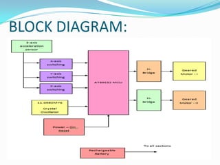
This document presents a project to develop a wheelchair control system using MEMS technology to recognize hand gestures. A MEMS 3-axis acceleration sensor detects the direction of the user's hand movement and sends signals to a microcontroller. The microcontroller then controls two DC geared motors and an H-bridge circuit to move the wheelchair in directions like left, right, front, or back depending on the hand gesture. A lead-acid battery provides power to the entire system. The goal is to enable physically disabled users to control the wheelchair through hand motions.
INTRODUCTION:
This projectis to develop a wheel chair control which is
useful to the physically disabled person with his hand
movement or his hand gesture recognition using MEMS
technology.
In MEMS we have Tilt register. When we change the
direction, the tilt registers values are changed and that values
are given to microcontroller.
Depending on the direction of the MEMS, microcontroller
controls the wheel chair directions like LEFT, RIGHT,
FRONT, and BACK.
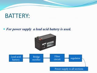
BATTERY:
For powersupply a lead acid battery is used.
Lead acid
battery
Bridge
rectifier
Filter
circuit
regulator
Power supply to all sections
5.
3-AXIS ACCELERATION SENSOR:
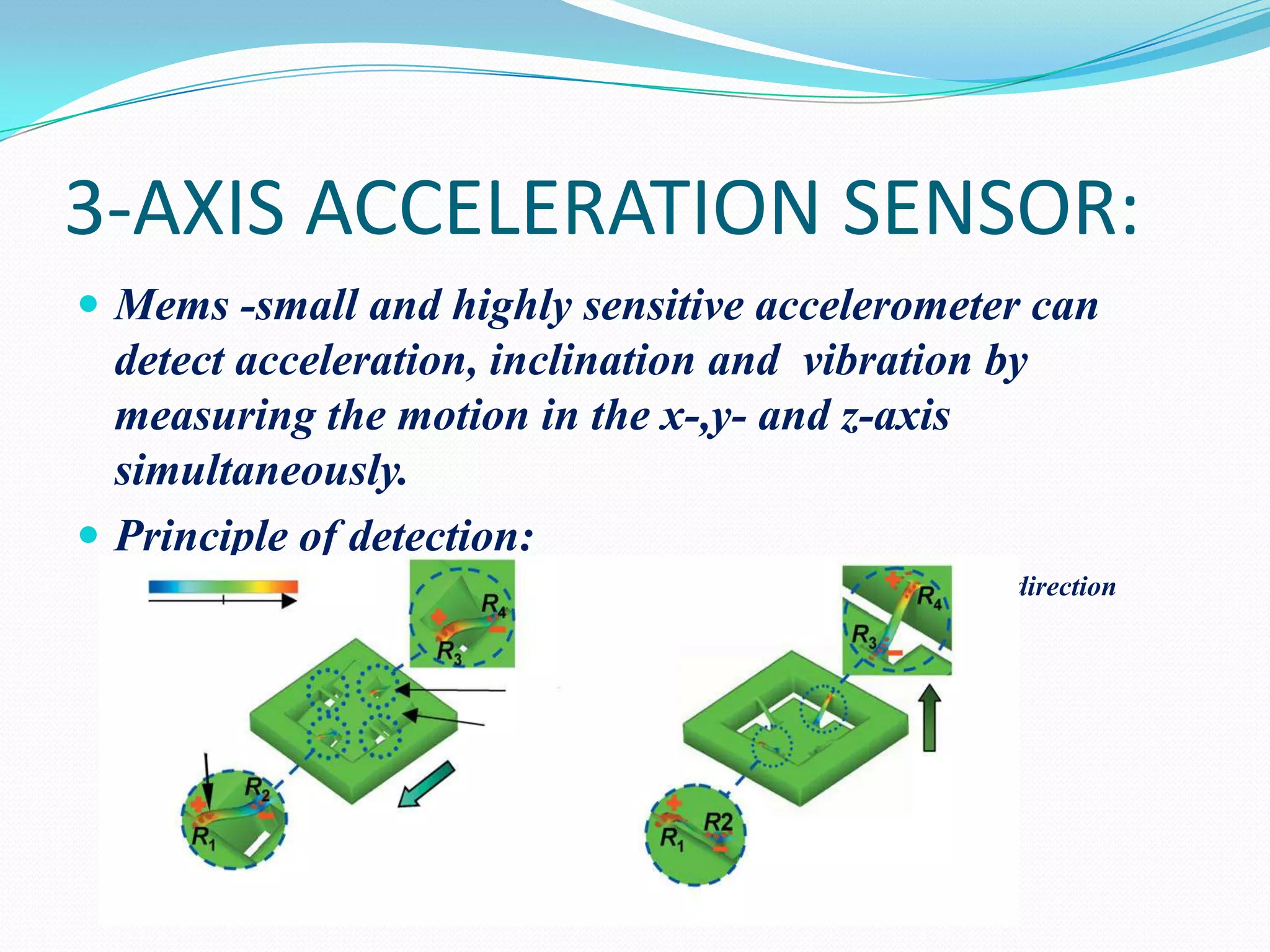
Mems -small and highly sensitive accelerometer can
detect acceleration, inclination and vibration by
measuring the motion in the x-,y- and z-axis
simultaneously.
Principle of detection:
Magnitude of stress
along x and y direction
along z-direction
6.
The MEMS3-axis accelerometer consists of a mass at
the center of the sensors chip, which is suspended by 4
beams doped with piezo resistive material.
When the sensor is subjected to acceleration in any
direction, the movement of the mass causes the 4 beams
to deform and so changes the resistance of in the piezo
material . This enables the sensor to detect the
acceleration motion.
7.
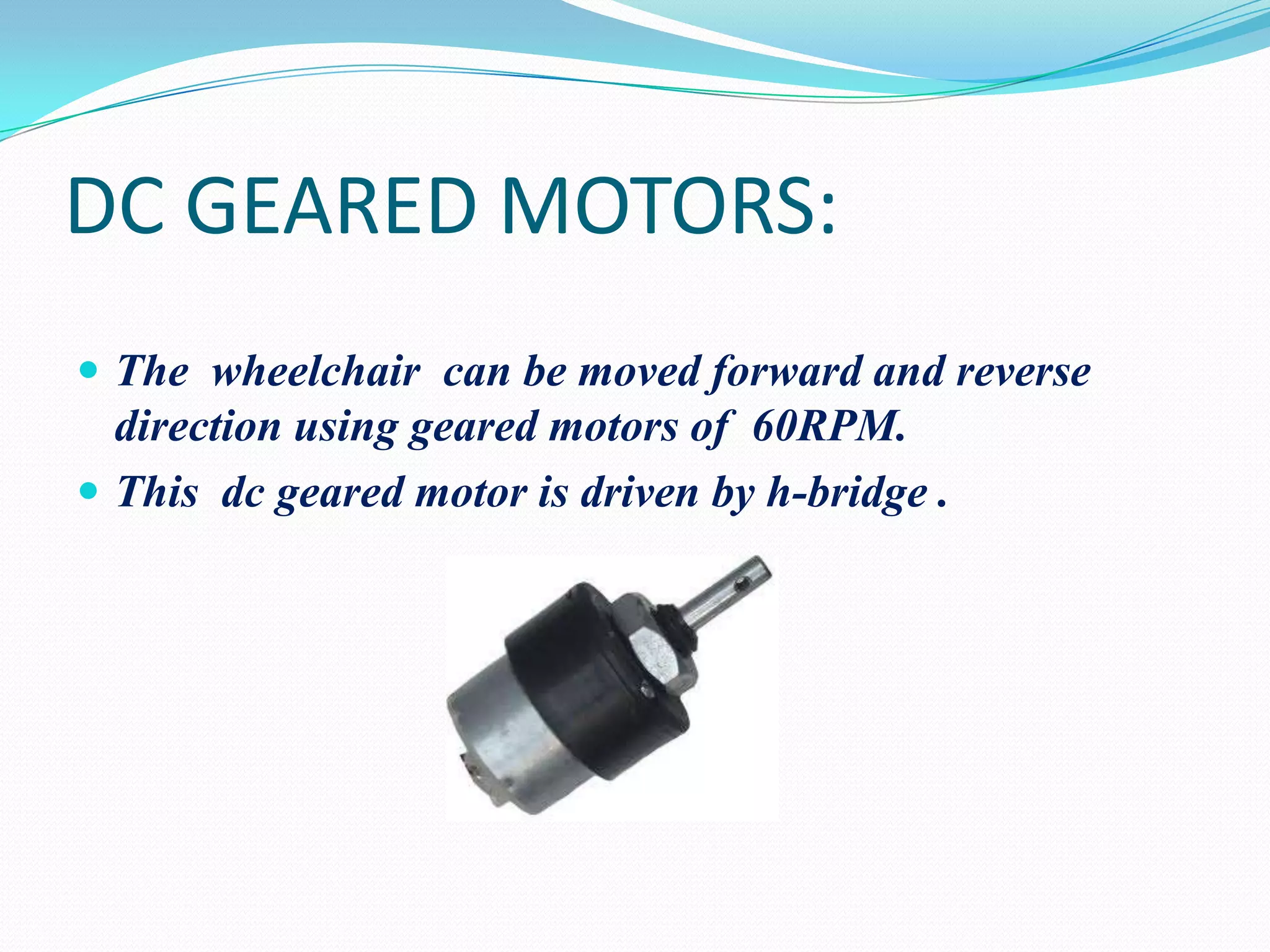
DC GEARED MOTORS:
The wheelchair can be moved forward and reverse
direction using geared motors of 60RPM.
This dc geared motor is driven by h-bridge .
8.
H-bridge:
An Hbridge is an electronic circuit that enables a
voltage to be applied across a load in either direction.
These circuits are often used in robotics and other
applications to allow DC motors to run forwards and
backwards.
An H bridge is built with four switches (solid-state or
mechanical).
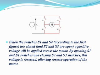
9.
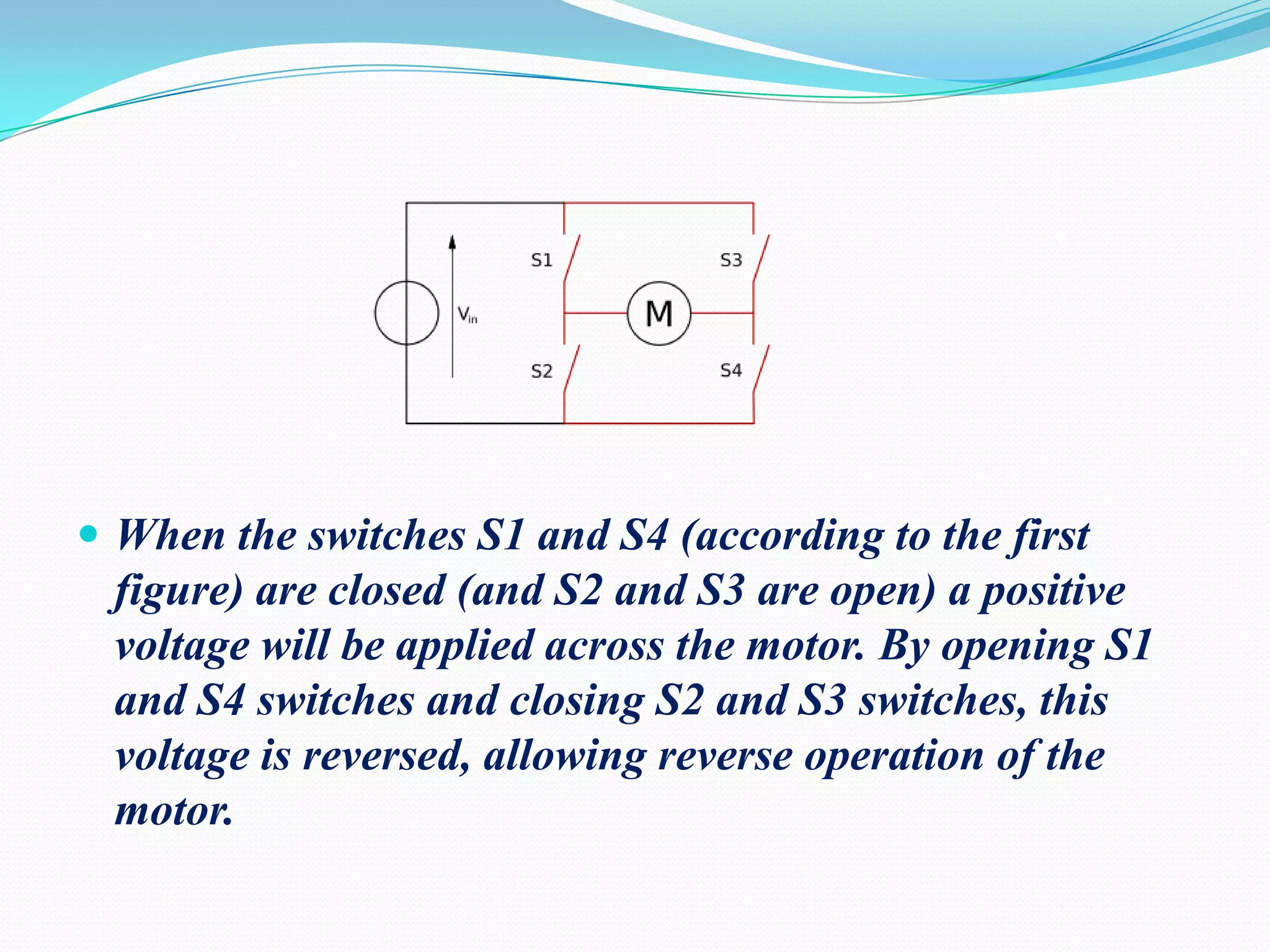
When theswitches S1 and S4 (according to the first
figure) are closed (and S2 and S3 are open) a positive
voltage will be applied across the motor. By opening S1
and S4 switches and closing S2 and S3 switches, this
voltage is reversed, allowing reverse operation of the
motor.