Downloaded 745 times


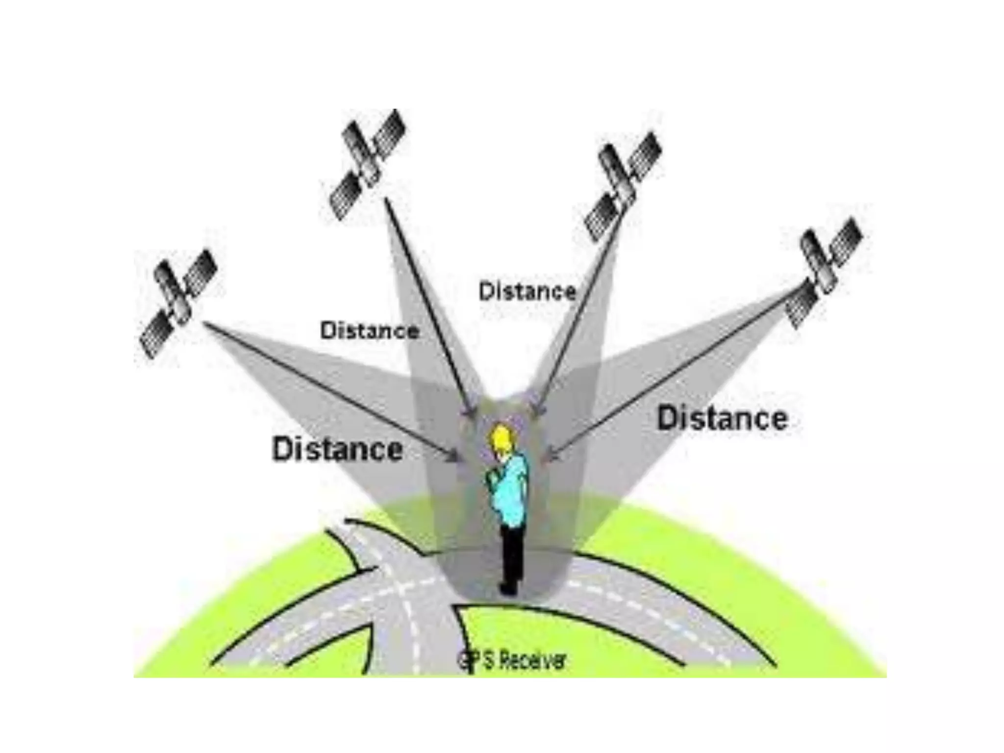
![The Global Positioning System (GPS) is a space-based satellite navigation system that
provides location and time information in all weather conditions, anywhere on or near the
Earth where there is an unobstructed line of sight to four or more GPS satellites.[1] The
system provides critical capabilities to military, civil and commercial users around the world.
It is maintained by the United States government and is freely accessible to anyone with a
GPS receiver.
Concept of GPS
A GPS receiver calculates its position by precisely timing the signals sent by GPS satellites
high above the Earth. Each satellite continually transmits messages that include:](https://image.slidesharecdn.com/miniprojectppt-150715024826-lva1-app6891/85/robotics-and-embedded-system-ppt-20-320.jpg)


![The Global Positioning System (GPS) is a space-based satellite navigation system that
provides location and time information in all weather conditions, anywhere on or near the
Earth where there is an unobstructed line of sight to four or more GPS satellites.[1] The
system provides critical capabilities to military, civil and commercial users around the world.
It is maintained by the United States government and is freely accessible to anyone with a
GPS receiver.
Concept of GPS
A GPS receiver calculates its position by precisely timing the signals sent by GPS satellites
high above the Earth. Each satellite continually transmits messages that include:](https://image.slidesharecdn.com/miniprojectppt-150715024826-lva1-app6891/75/robotics-and-embedded-system-ppt-20-2048.jpg)
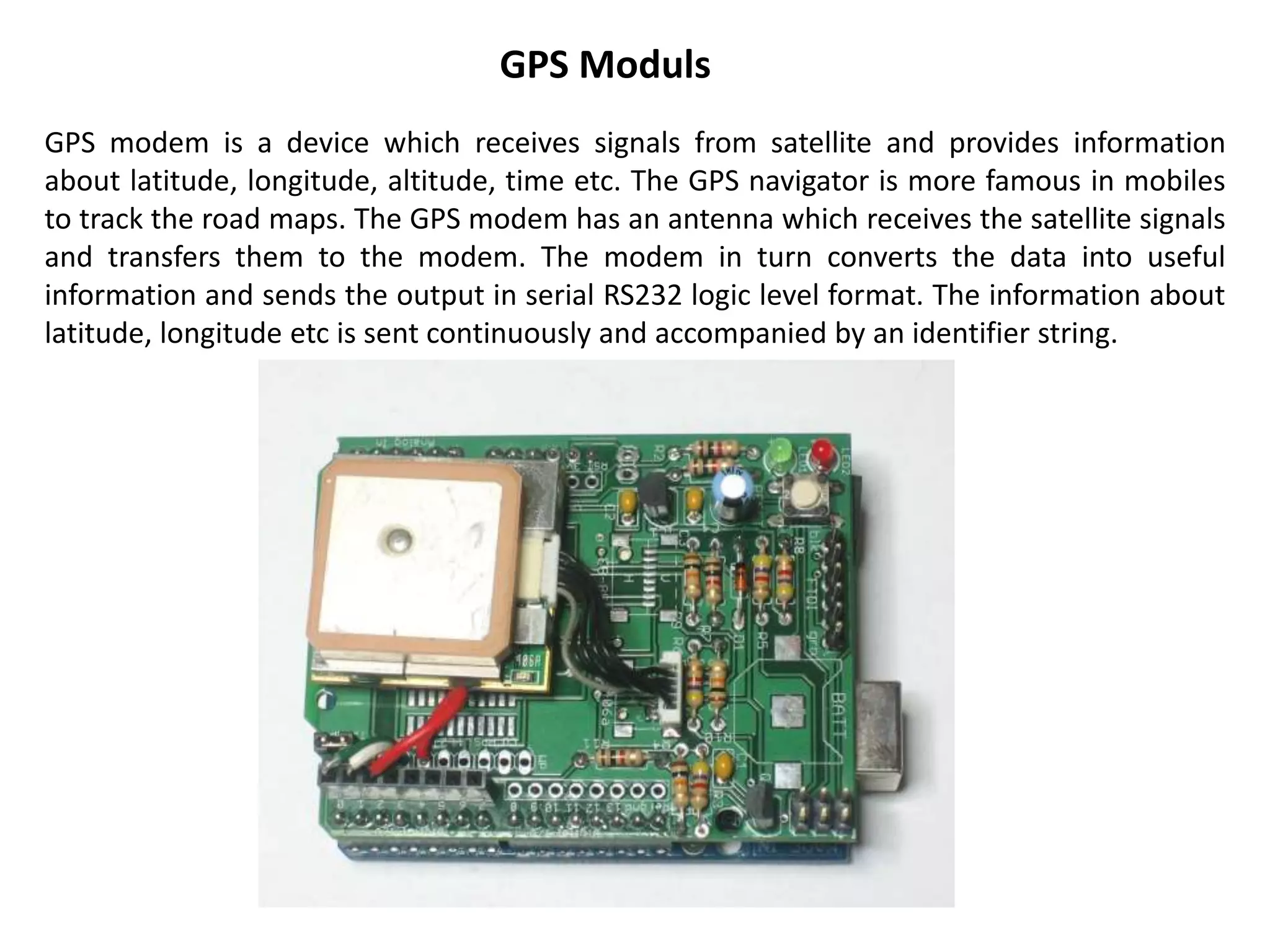


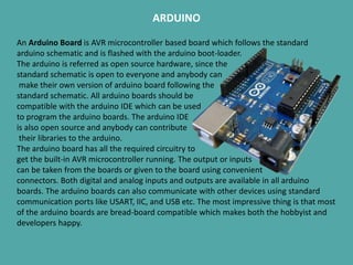
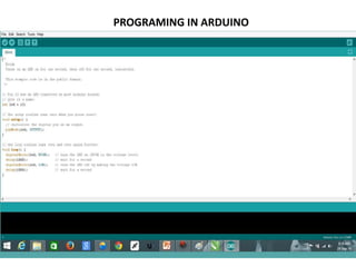
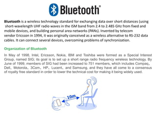
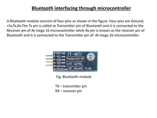
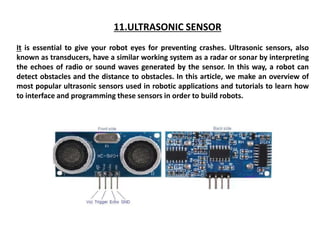
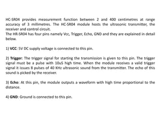
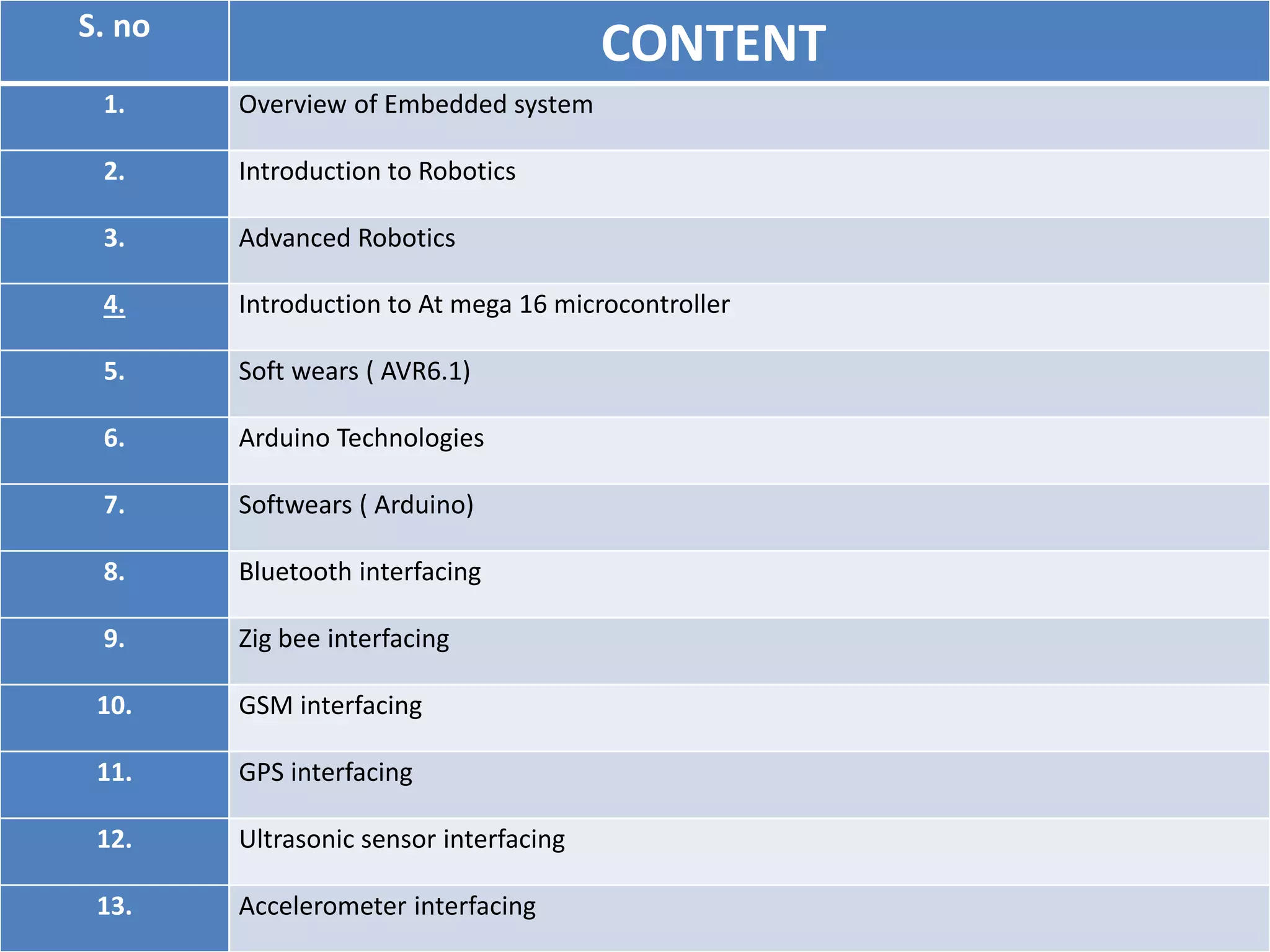
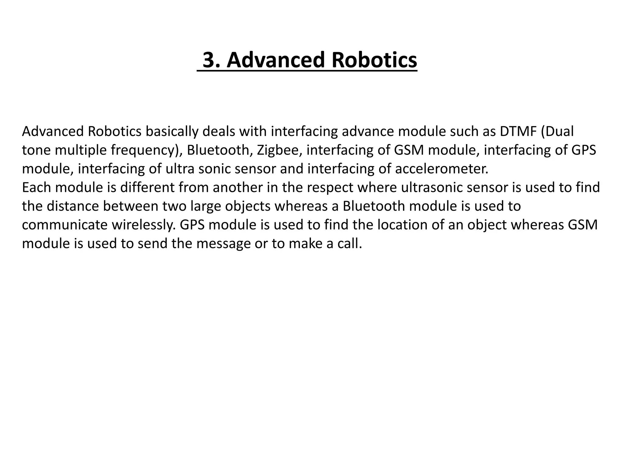
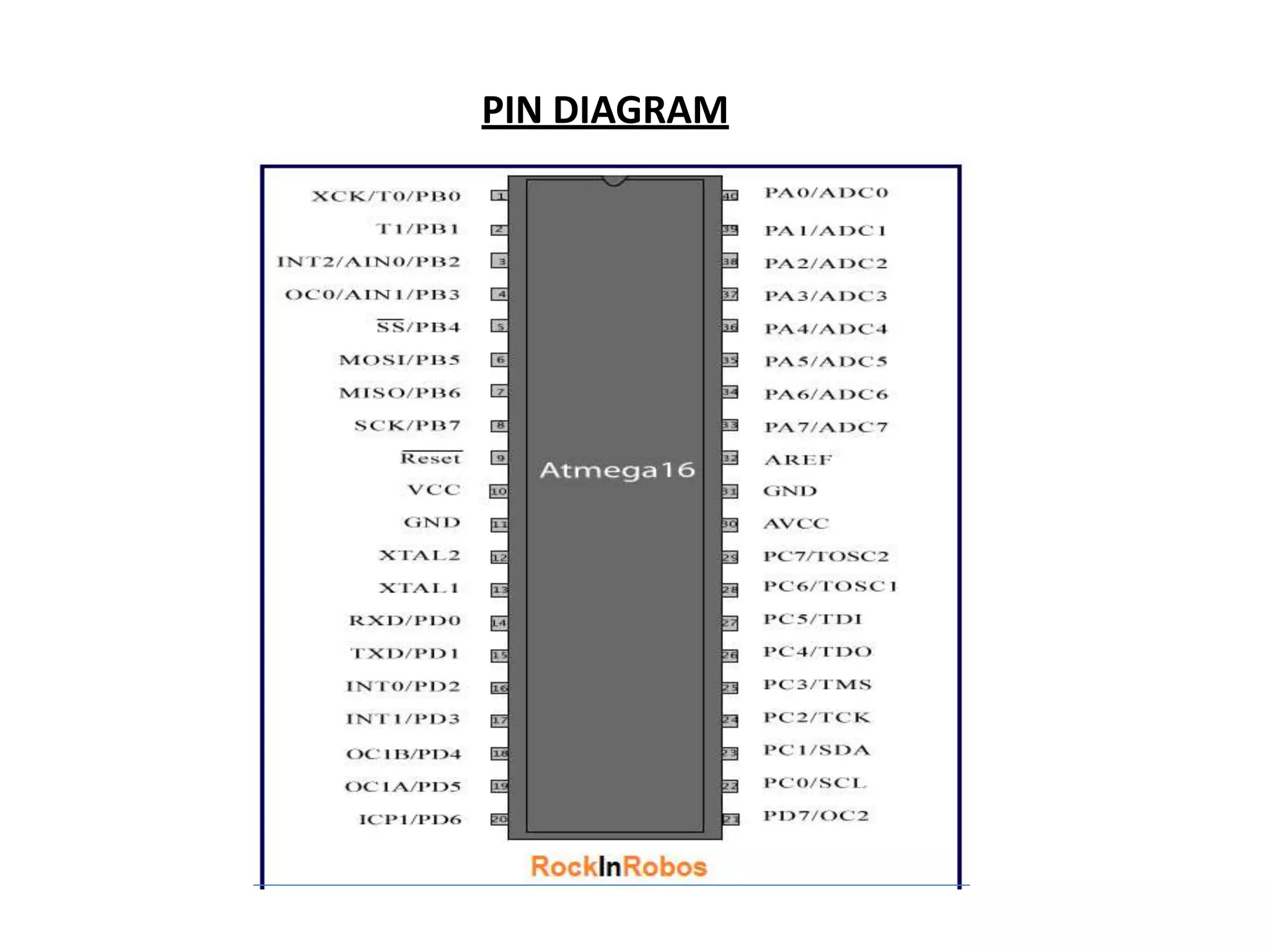
This document provides an overview of robotics and embedded systems topics, including definitions of key concepts. It discusses embedded systems, robotics, advanced robotics involving various sensors and modules. It also introduces the ATmega16 microcontroller and programming in Arduino. Finally, it covers interfacing technologies like Bluetooth, Zigbee, GPS and ultrasonic sensors with microcontrollers.


![Waching machine[1]](https://cdn.slidesharecdn.com/ss_thumbnails/wachingmachine1-190420045344-thumbnail.jpg?width=600ounds&width=560&fit=bounds)


![Smart accident detector and intimator [autosaved]](https://cdn.slidesharecdn.com/ss_thumbnails/smartaccidentdetectorandintimatorautosaved-180331150920-thumbnail.jpg?width=600ounds&width=560&fit=bounds)


