Downloaded 121 times


The document presents an overview of Hertz and Marconi antennas, detailing their history, construction, and applications. It discusses the characteristics, such as radiation patterns, gain, and directivity for both types of antennas, highlighting their differences and similarities. Additionally, it provides references for further reading.
Introduction to Hertz and Marconi antennas including history, construction, and content outline.
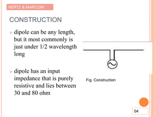
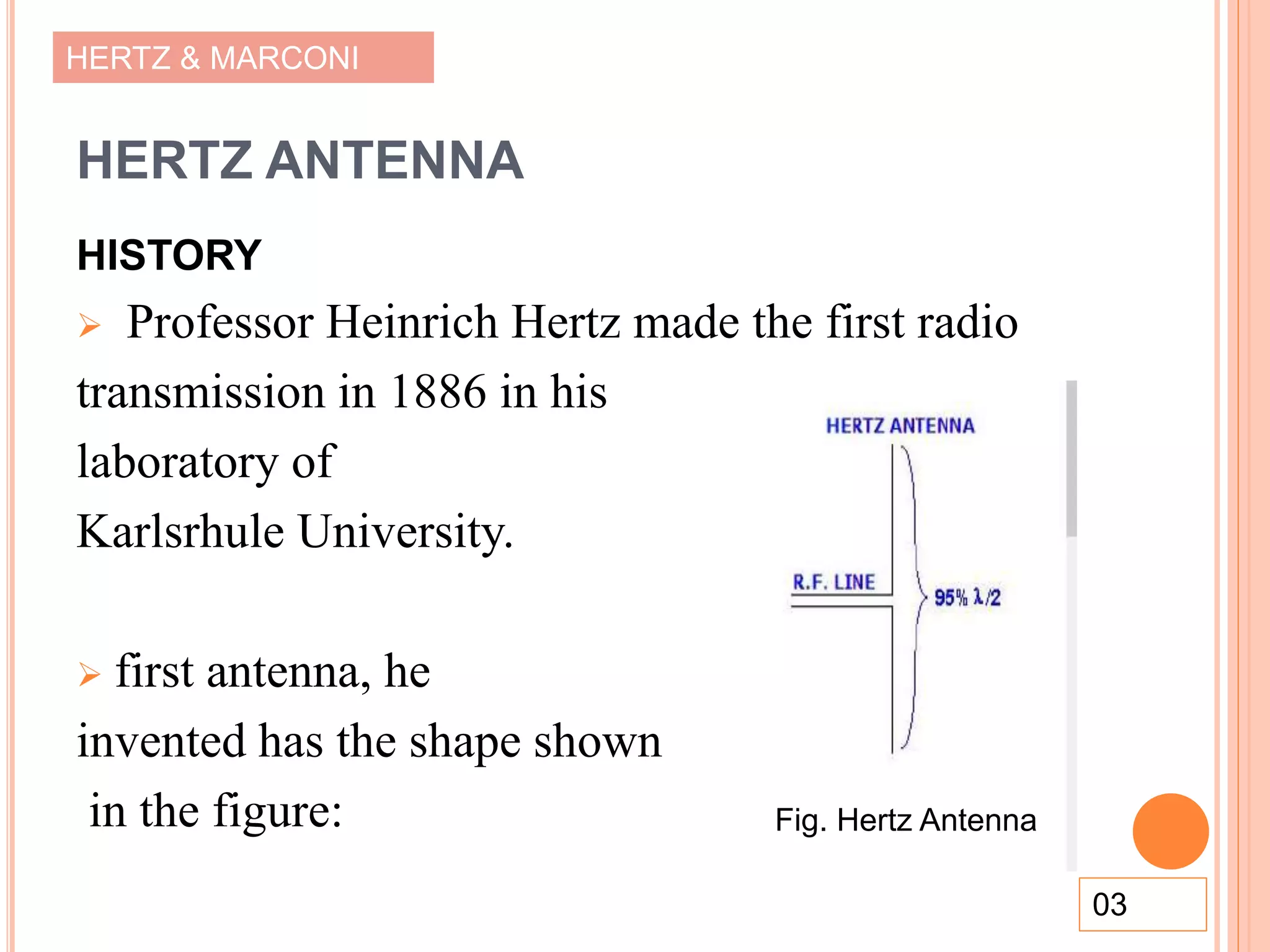
Hertz antenna, first radio transmission in 1886, and construction details including impedance.
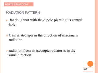
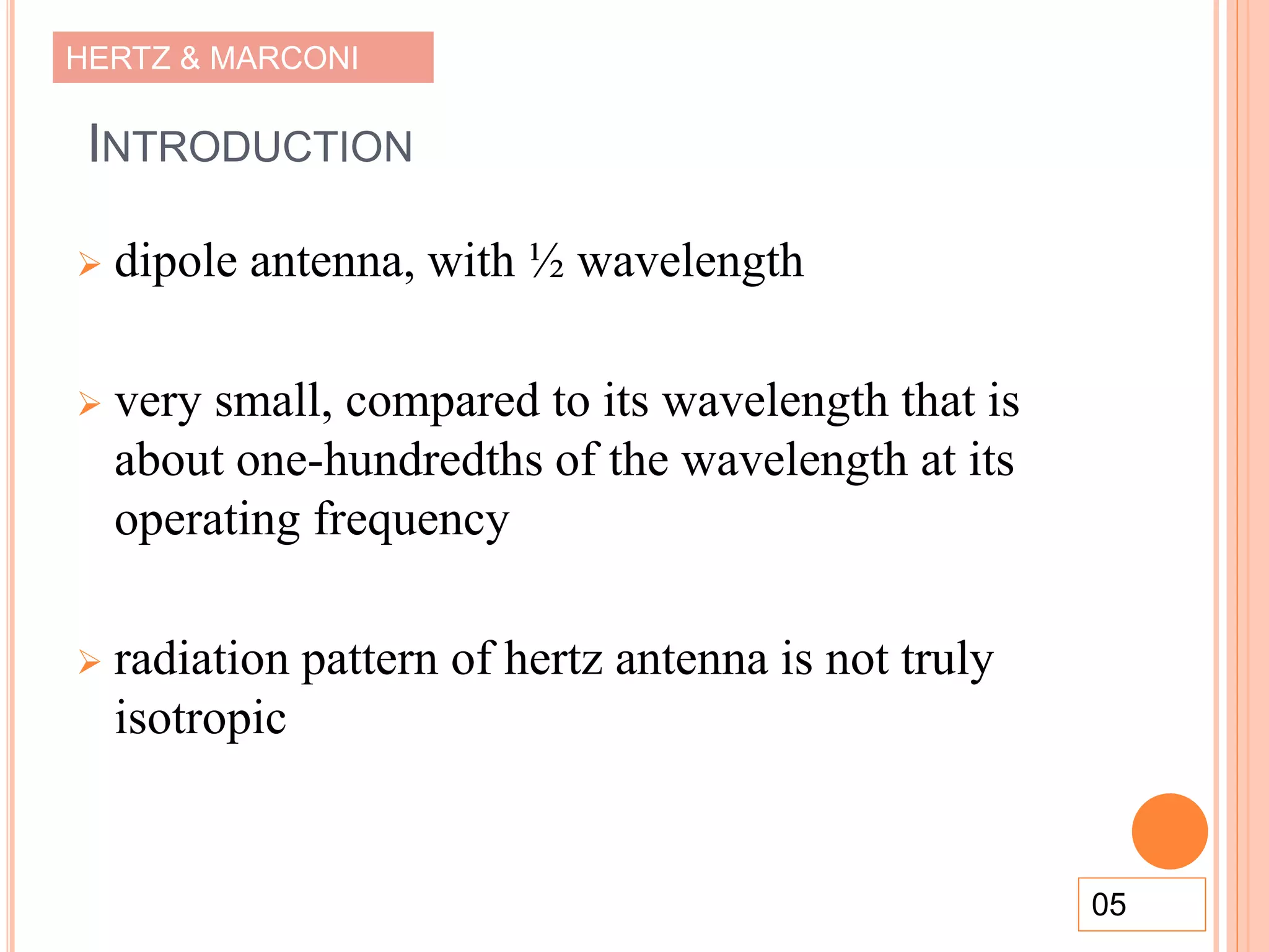
Introduction to dipole antennas and non-isotropic radiation patterns, including gain characteristics.
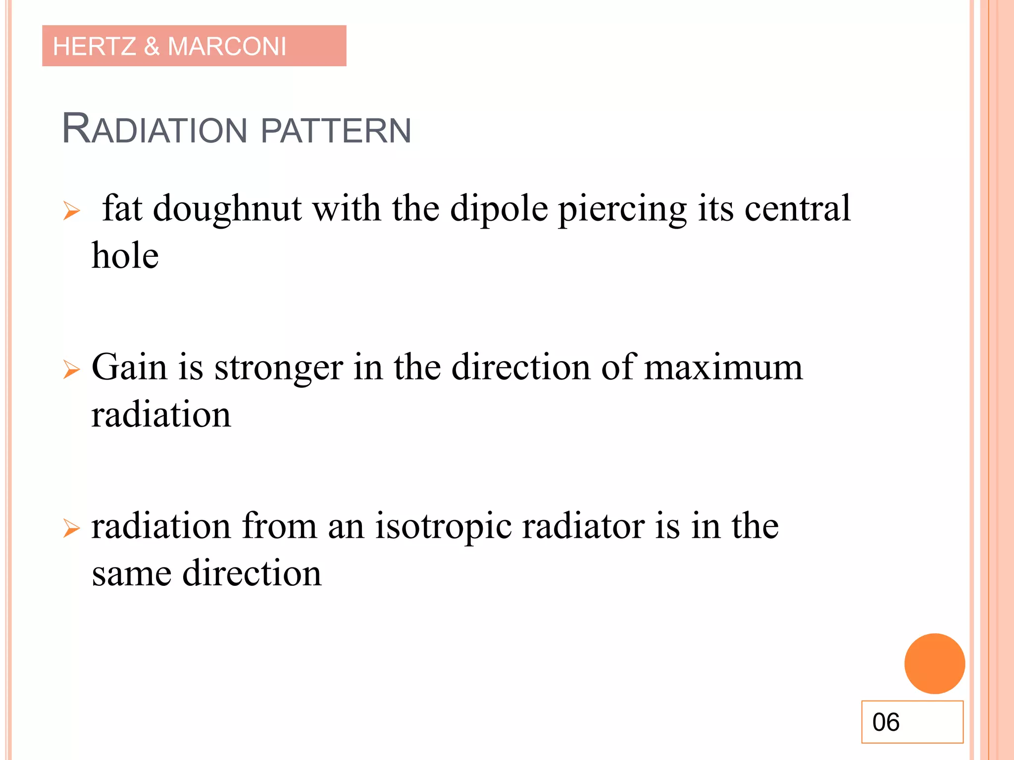
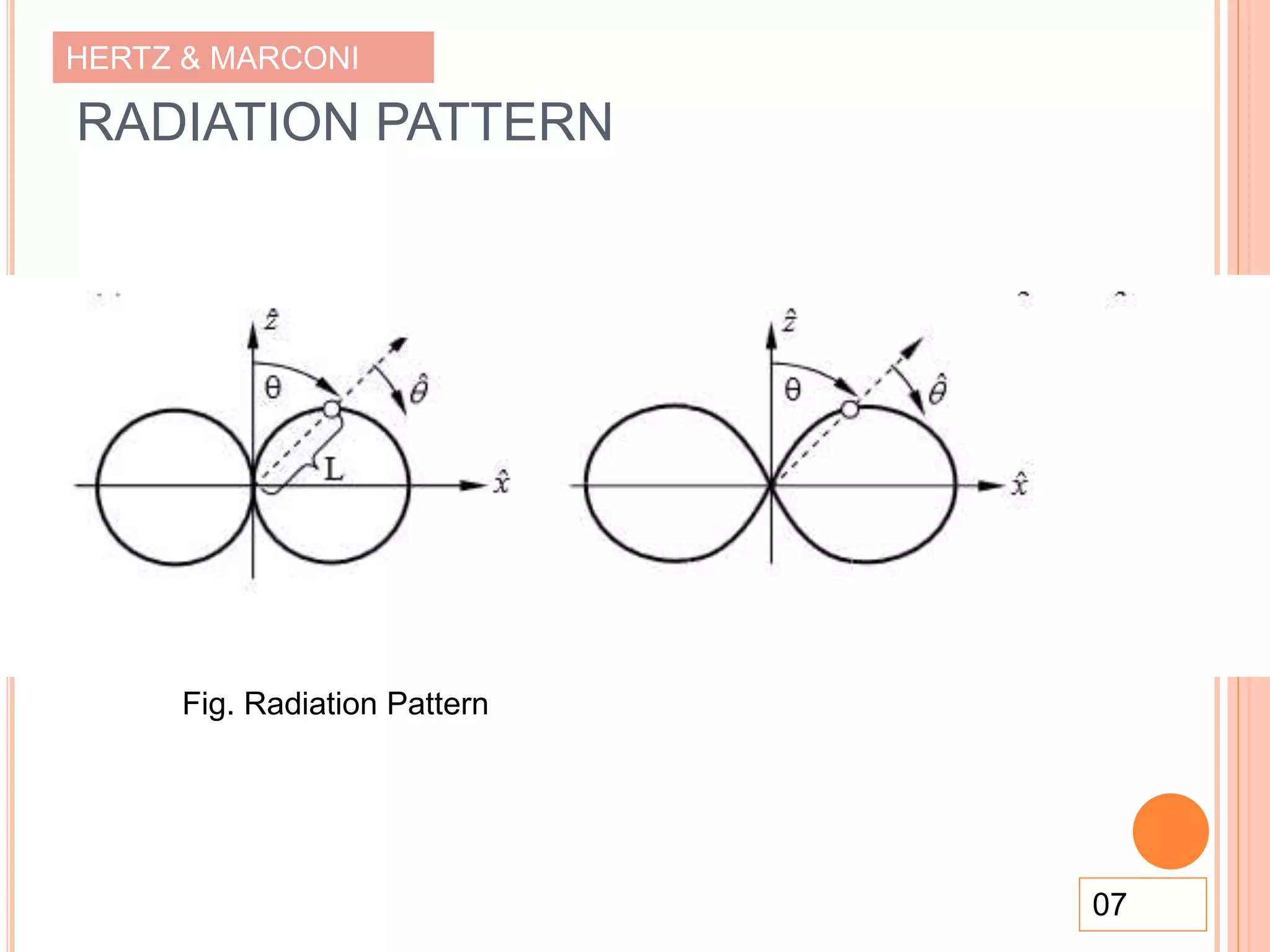
Illustration of radiation pattern and gain specifications of the Hertz antenna, highlighting directivity.
Common applications of Hertz antennas, including use in small TV antenna setups.
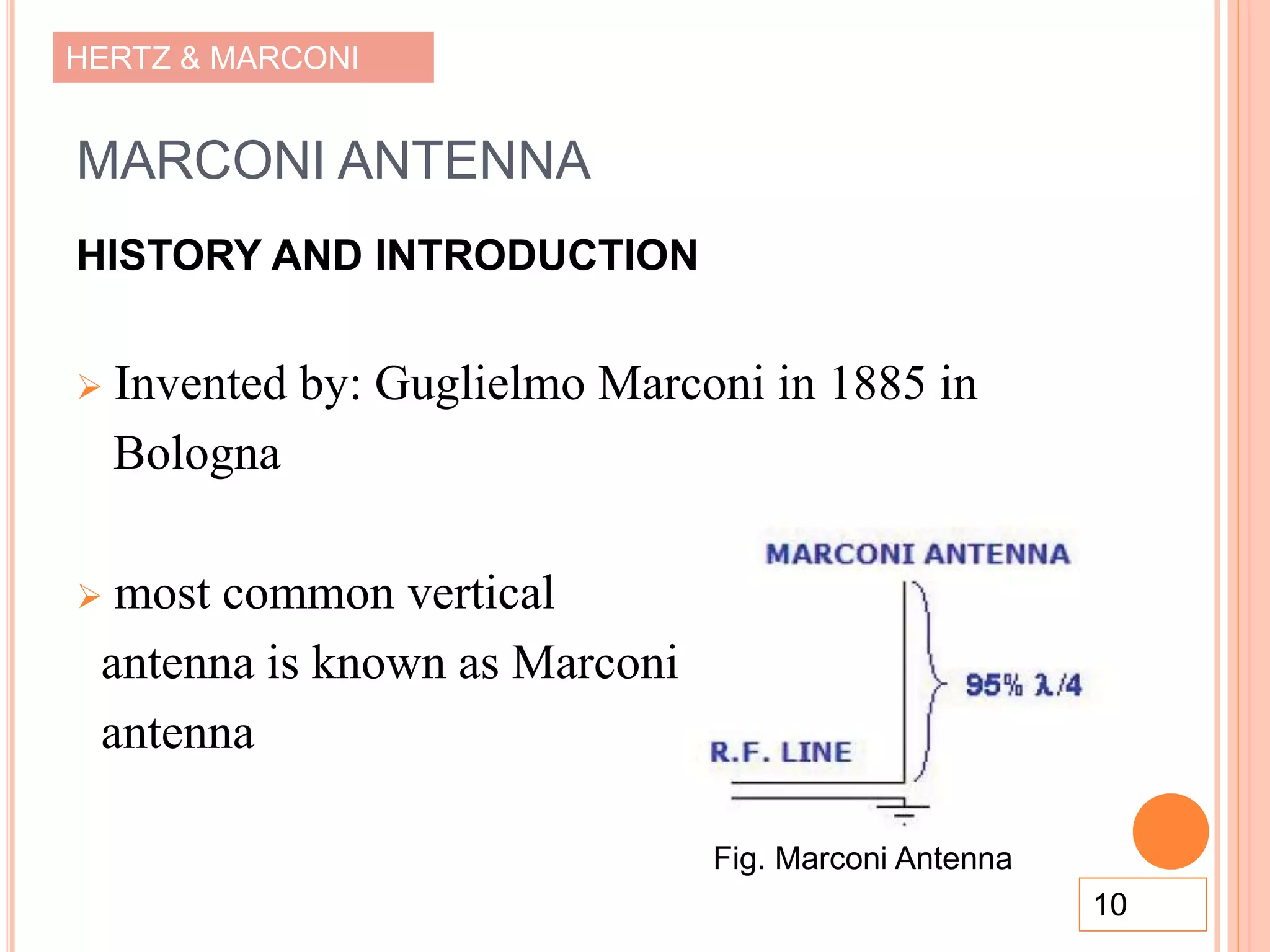
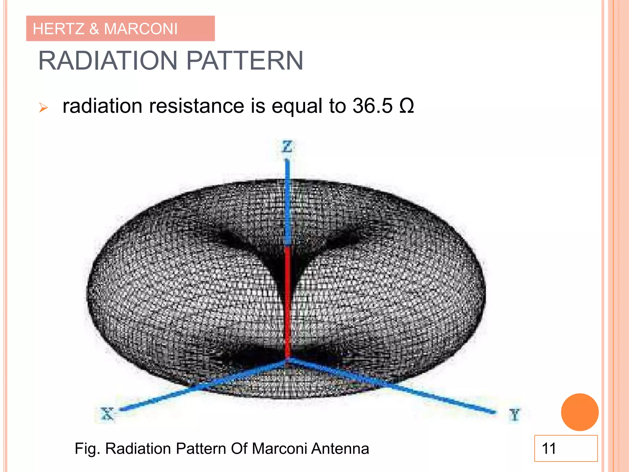
Development of Marconi antenna by Guglielmo Marconi in 1885 and its radiation resistance properties.
Design specifics of the Marconi antenna and its application in high power radio broadcasting.
Comparison of electrical and physical characteristics between Hertz and Marconi antennas.
Citations for sources consulted in the study of Hertz and Marconi antennas.
Final slides concluding the presentation, no specific content was provided.


