Download to read offline


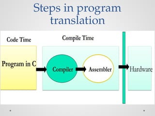


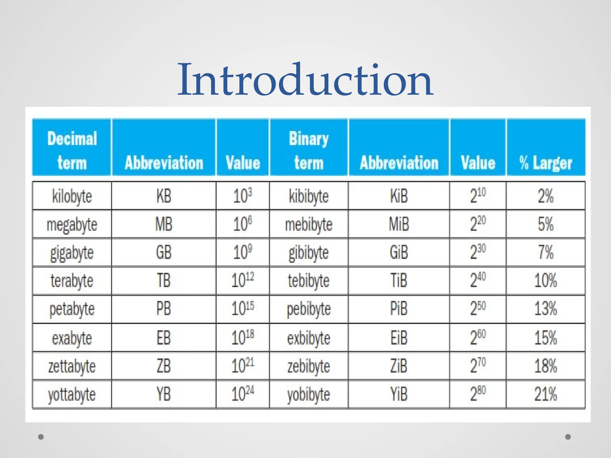
![Load/Store Instructions
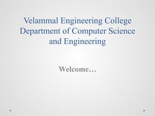
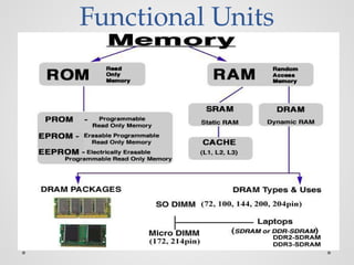
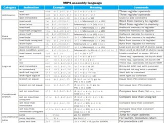
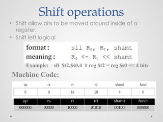
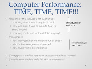
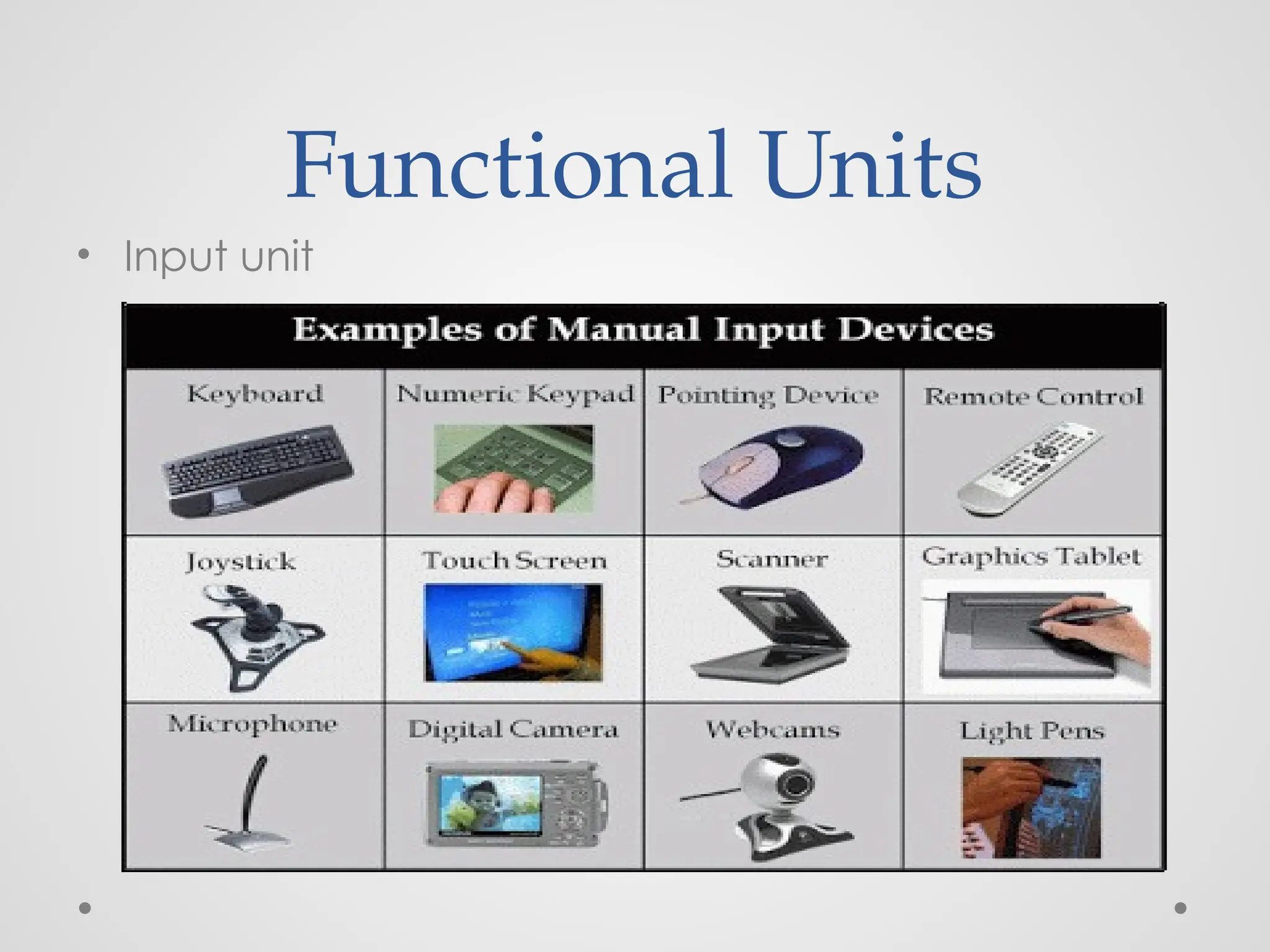
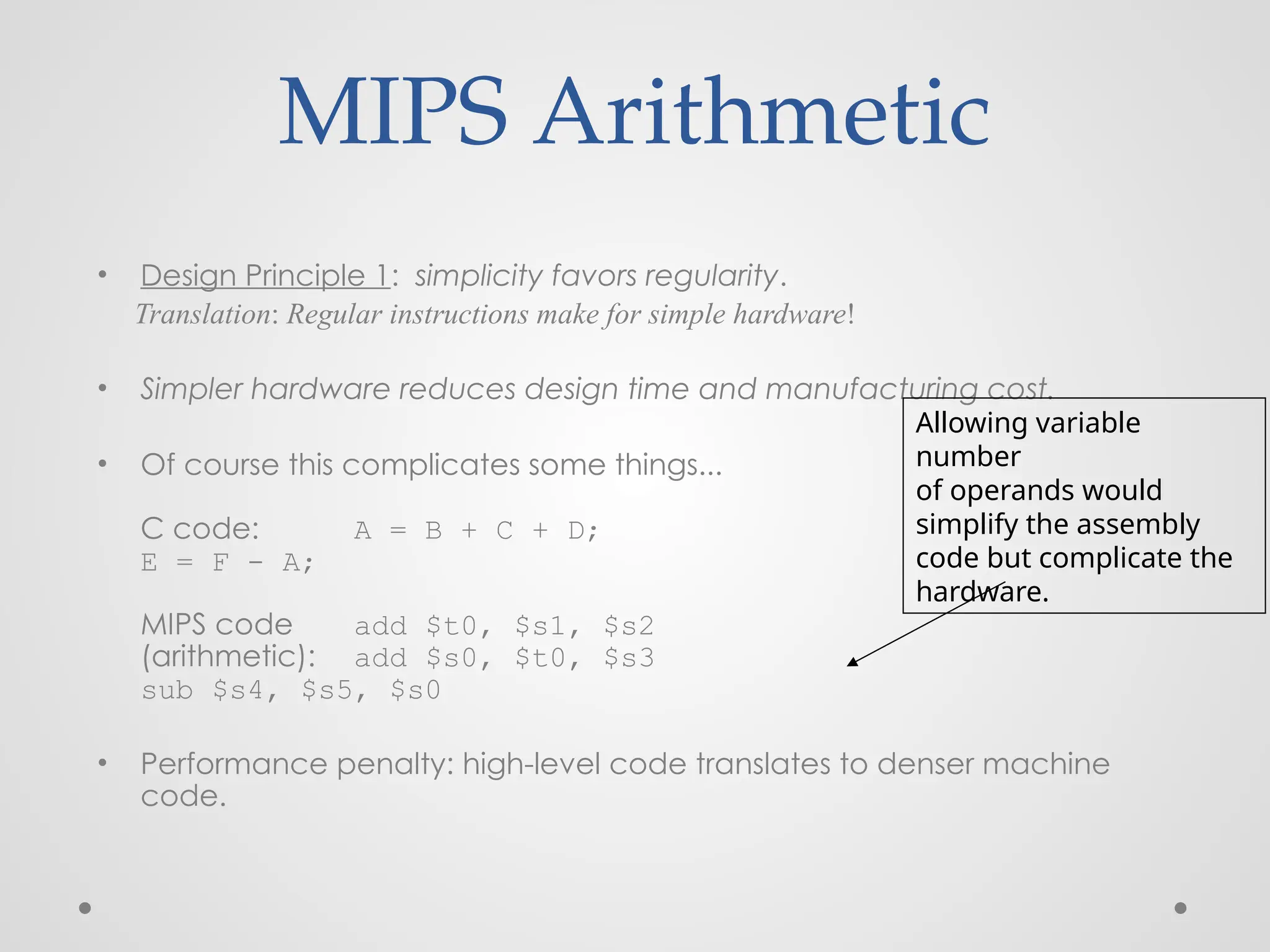
• Load and store instructions
• Example:
C code: A[8] = h + A[8];
MIPS code (load): lw $t0, 32($s3)
(arithmetic): add $t0, $s2, $t0
(store): sw $t0, 32($s3)
• Load word has destination first, store has destination last
• Remember MIPS arithmetic operands are registers, not
memory locations
o therefore, words must first be moved from memory to registers
using loads before they can be operated on; then result can be
stored back to memory
offset address
value](https://image.slidesharecdn.com/unitica-241211143358-d81c66d9/85/Introduction-to-Computer-Architecture-unit-1-56-320.jpg)
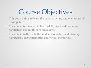
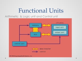
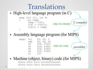
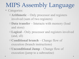
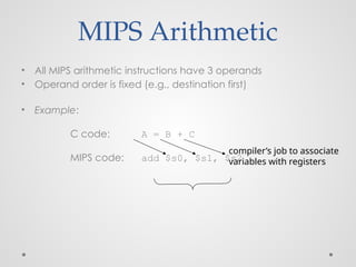
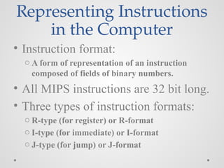
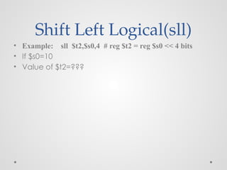
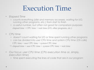
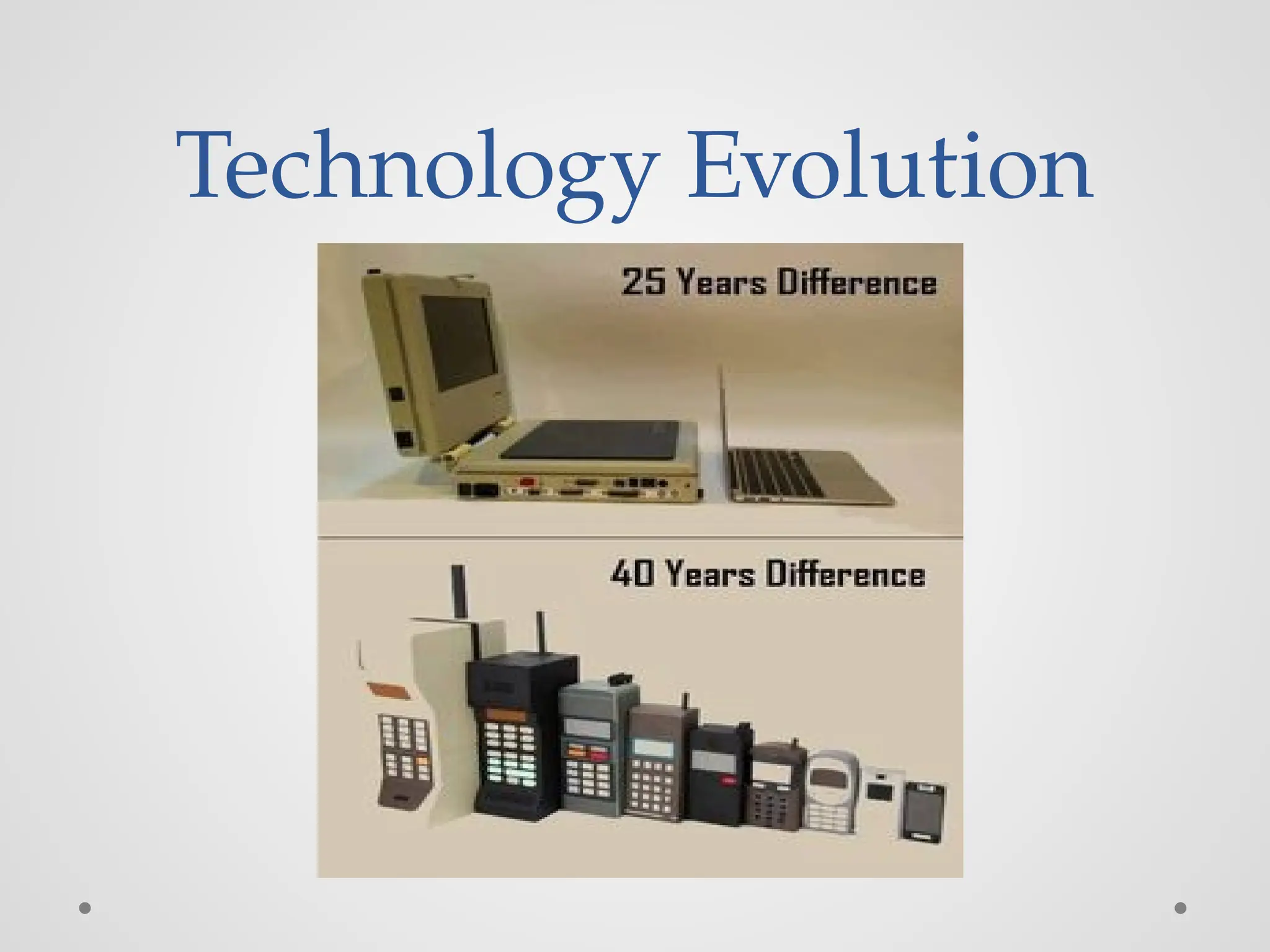
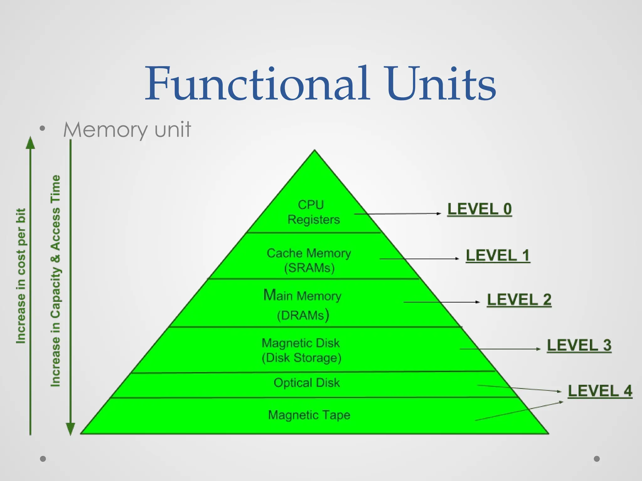
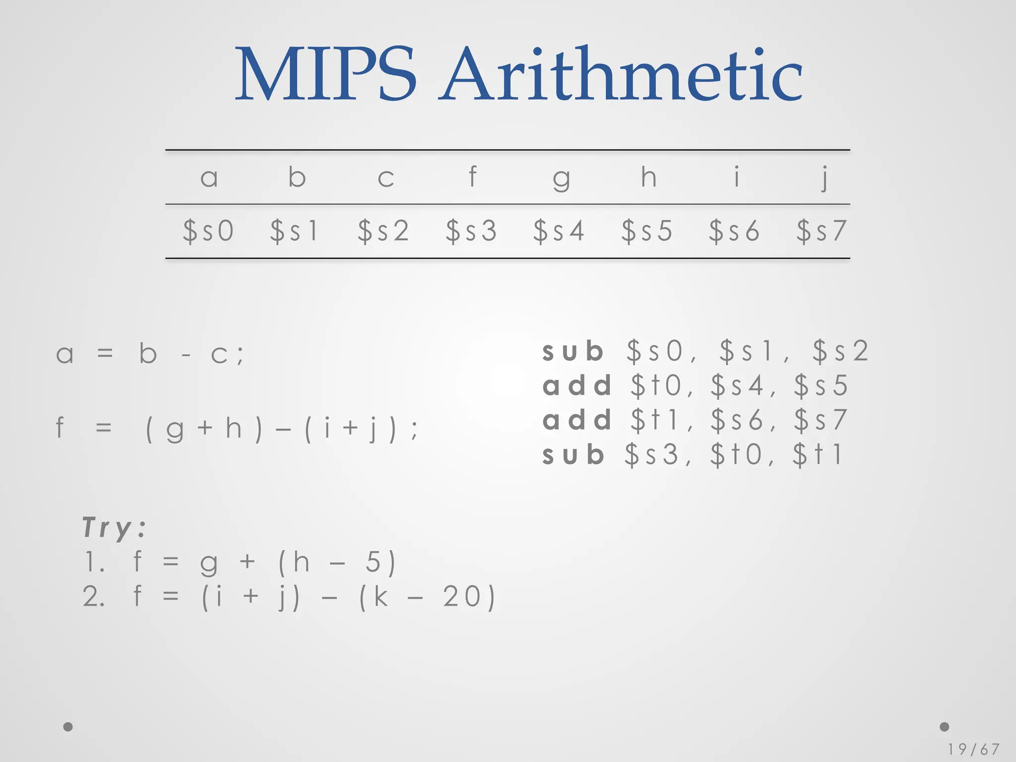
![So far we’ve learned:
• MIPS
o loading words but addressing bytes
o arithmetic on registers only
• Instruction Meaning
add $s1, $s2, $s3 $s1 = $s2 + $s3
sub $s1, $s2, $s3 $s1 = $s2 – $s3
lw $s1, 100($s2) $s1 = Memory[$s2+100]
sw $s1, 100($s2) Memory[$s2+100]= $s1
• Try:Find the assembly code of B[8]=A[i]+A[j];
A and B available in $s6 and $s7
respectively
$so-$s5 consists of the values f-j](https://image.slidesharecdn.com/unitica-241211143358-d81c66d9/85/Introduction-to-Computer-Architecture-unit-1-57-320.jpg)


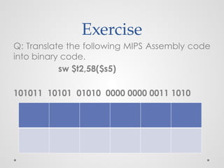
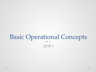
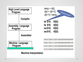
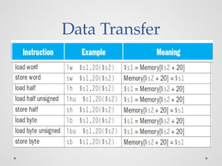
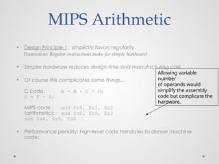
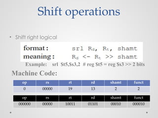
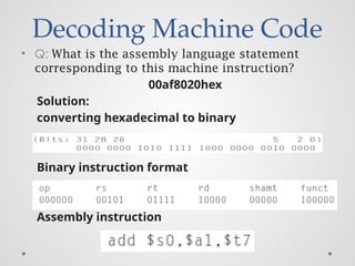
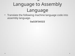
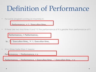
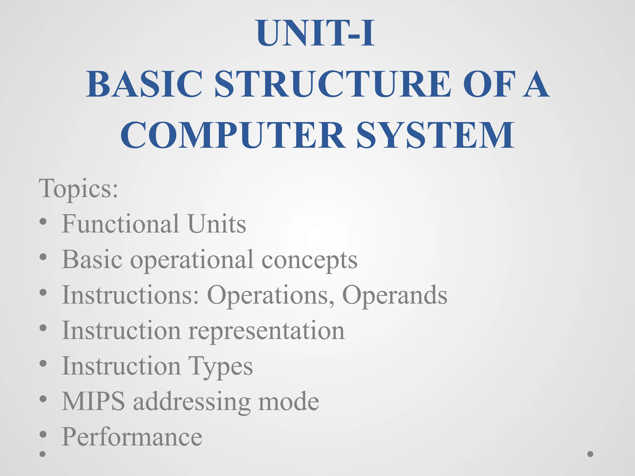
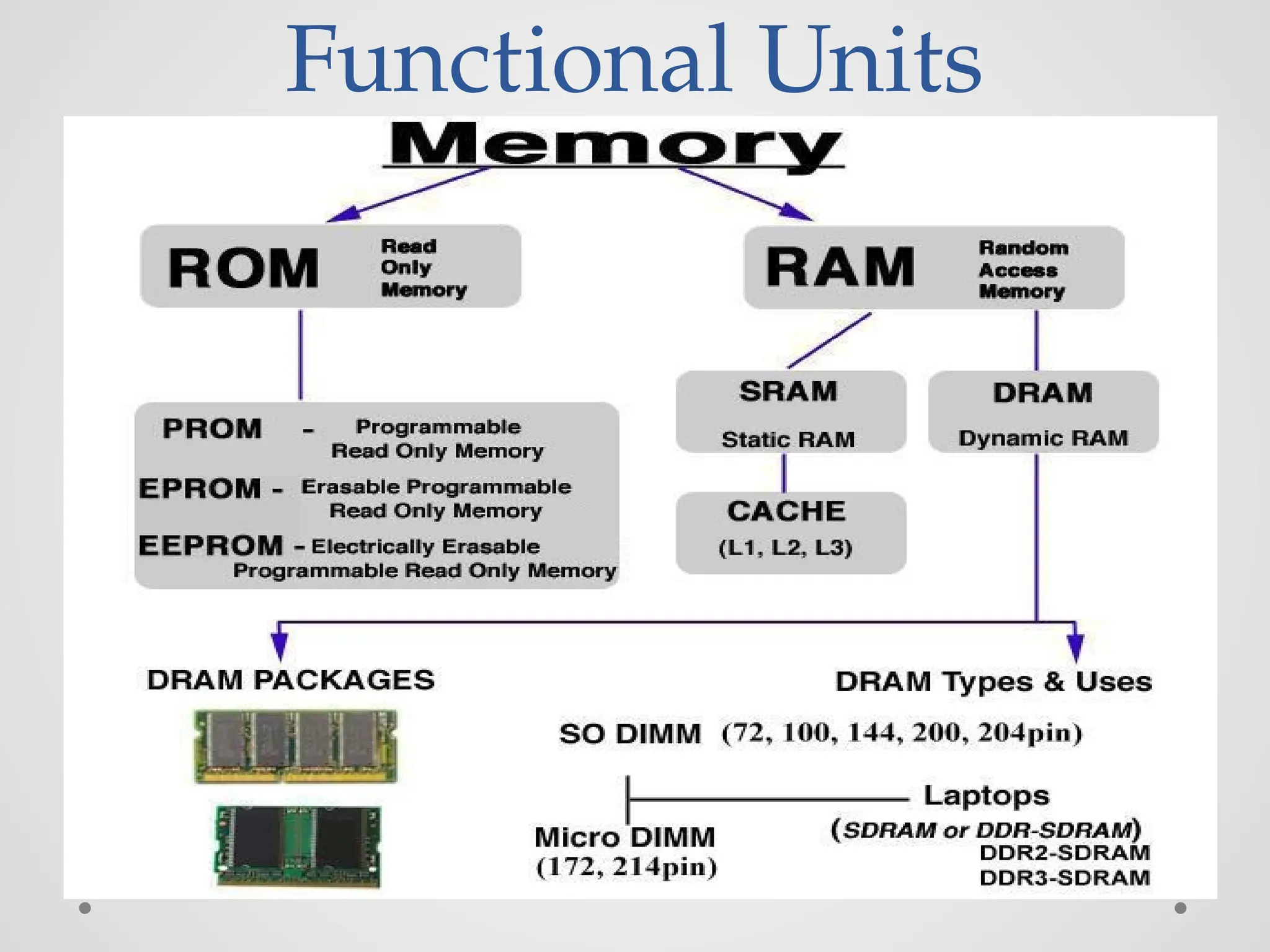
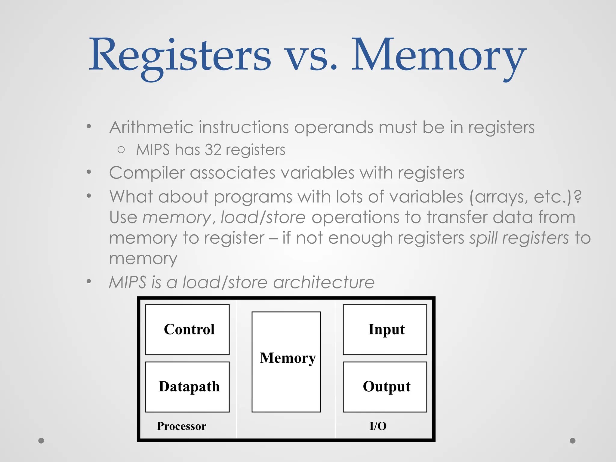
![Translating High level Language
into Machine Language
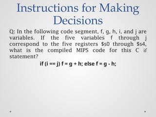
Q: Consider the following high level statement
A[300] = h + A[300];
If $t1 has the base of the array A and $s2 corresponds to
h, What is the MIPS machine language code?](https://image.slidesharecdn.com/unitica-241211143358-d81c66d9/85/Introduction-to-Computer-Architecture-unit-1-73-320.jpg)


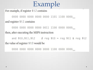

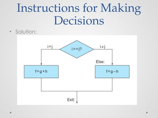
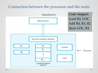
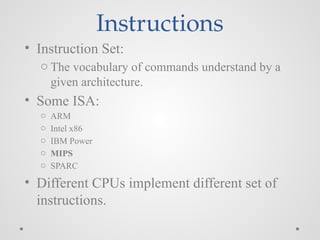
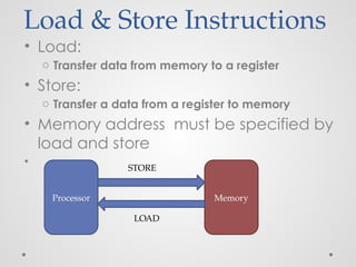
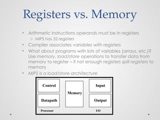
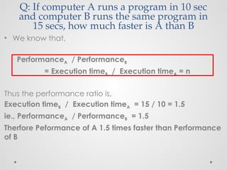
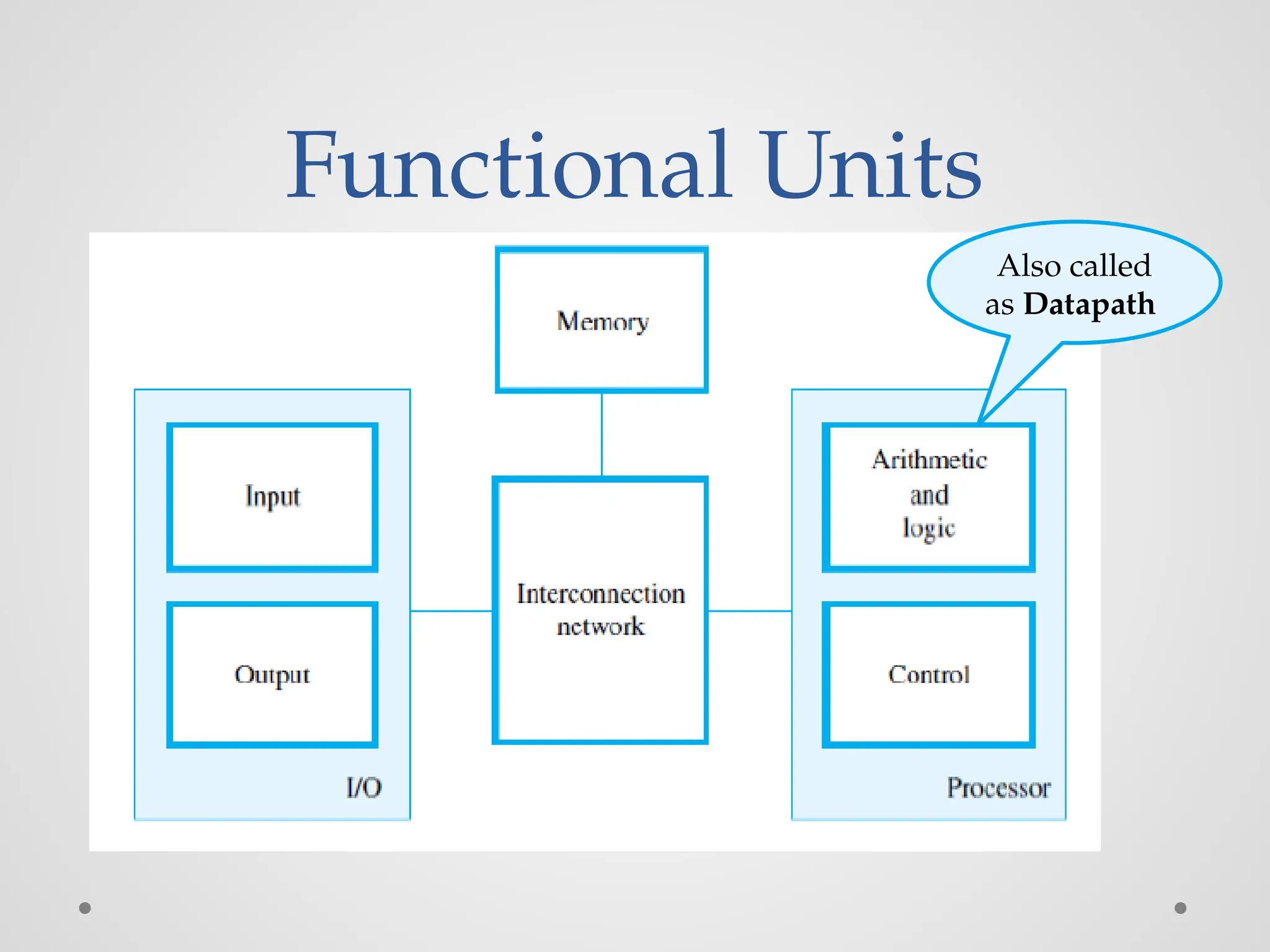
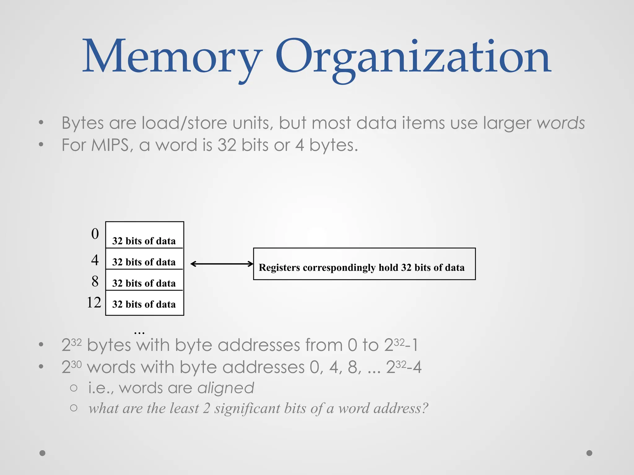
![Compiling a while Loop
in C
while (save[i] == k)
i += 1;
Assume that i and k correspond to registers $s3 and
$s5 and the base of the array save is in $s6. What is
the MIPS assembly code corresponding to this C
segment?](https://image.slidesharecdn.com/unitica-241211143358-d81c66d9/85/Introduction-to-Computer-Architecture-unit-1-85-320.jpg)
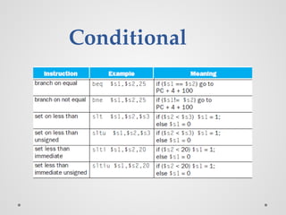
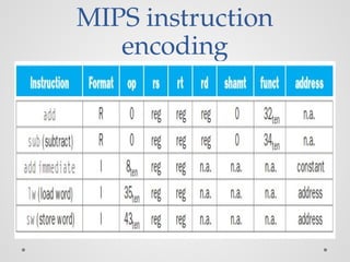
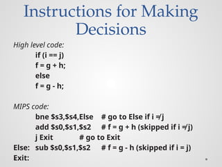
![Compiling a while Loop
in C
while (save[i] == k)
i += 1;
1. load save[i] into a temporary register
1. add i to the base of array save to form the address
2. performs the loop test
1. go to Exit if save[i] ≠ k
3. adds 1 to I
4. back to the while test at the top of the loop
5. Exit](https://image.slidesharecdn.com/unitica-241211143358-d81c66d9/85/Introduction-to-Computer-Architecture-unit-1-86-320.jpg)
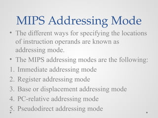
![while (save[i] == k)
i += 1;
Assume that i and k correspond to registers $s3 and
$s5 and the base of the array save is in $s6. What is
the MIPS assembly code corresponding to this C
segment?
Solution:
Loop: sll $t1,$s3,2 # Temp reg $t1 = i * 4
add $t1,$t1,$s6 # $t1 = address of save[i]
lw $t0,0($t1) # Temp reg $t0 = save[i]
bne $t0,$s5, Exit # go to Exit if save[i] ≠ k
addi $s3,$s3,1 # i = i + 1
j Loop # go to Loop
Exit:](https://image.slidesharecdn.com/unitica-241211143358-d81c66d9/85/Introduction-to-Computer-Architecture-unit-1-87-320.jpg)

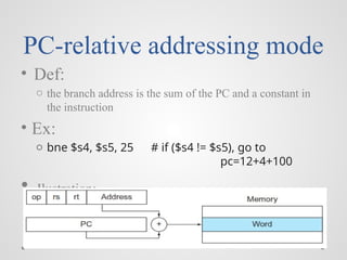
![Base or displacement
addressing mode
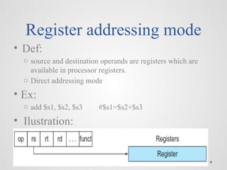
• Def:
o the operand is at the memory location whose address is the
sum of a register and a constant in the instruction
o Indirect addressing mode
• Ex:
o lw $s1, 20 ($s3) #$s1= Memory[$s3+20]
• Ilustration:](https://image.slidesharecdn.com/unitica-241211143358-d81c66d9/85/Introduction-to-Computer-Architecture-unit-1-91-320.jpg)


![Load/Store Instructions
• Load and store instructions
• Example:
C code: A[8] = h + A[8];
MIPS code (load): lw $t0, 32($s3)
(arithmetic): add $t0, $s2, $t0
(store): sw $t0, 32($s3)
• Load word has destination first, store has destination last
• Remember MIPS arithmetic operands are registers, not
memory locations
o therefore, words must first be moved from memory to registers
using loads before they can be operated on; then result can be
stored back to memory
offset address
value](https://image.slidesharecdn.com/unitica-241211143358-d81c66d9/75/Introduction-to-Computer-Architecture-unit-1-56-2048.jpg)
![So far we’ve learned:
• MIPS
o loading words but addressing bytes
o arithmetic on registers only
• Instruction Meaning
add $s1, $s2, $s3 $s1 = $s2 + $s3
sub $s1, $s2, $s3 $s1 = $s2 – $s3
lw $s1, 100($s2) $s1 = Memory[$s2+100]
sw $s1, 100($s2) Memory[$s2+100]= $s1
• Try:Find the assembly code of B[8]=A[i]+A[j];
A and B available in $s6 and $s7
respectively
$so-$s5 consists of the values f-j](https://image.slidesharecdn.com/unitica-241211143358-d81c66d9/75/Introduction-to-Computer-Architecture-unit-1-57-2048.jpg)


![Translating High level Language
into Machine Language
Q: Consider the following high level statement
A[300] = h + A[300];
If $t1 has the base of the array A and $s2 corresponds to
h, What is the MIPS machine language code?](https://image.slidesharecdn.com/unitica-241211143358-d81c66d9/75/Introduction-to-Computer-Architecture-unit-1-73-2048.jpg)


![Compiling a while Loop
in C
while (save[i] == k)
i += 1;
Assume that i and k correspond to registers $s3 and
$s5 and the base of the array save is in $s6. What is
the MIPS assembly code corresponding to this C
segment?](https://image.slidesharecdn.com/unitica-241211143358-d81c66d9/75/Introduction-to-Computer-Architecture-unit-1-85-2048.jpg)
![Compiling a while Loop
in C
while (save[i] == k)
i += 1;
1. load save[i] into a temporary register
1. add i to the base of array save to form the address
2. performs the loop test
1. go to Exit if save[i] ≠ k
3. adds 1 to I
4. back to the while test at the top of the loop
5. Exit](https://image.slidesharecdn.com/unitica-241211143358-d81c66d9/75/Introduction-to-Computer-Architecture-unit-1-86-2048.jpg)
![while (save[i] == k)
i += 1;
Assume that i and k correspond to registers $s3 and
$s5 and the base of the array save is in $s6. What is
the MIPS assembly code corresponding to this C
segment?
Solution:
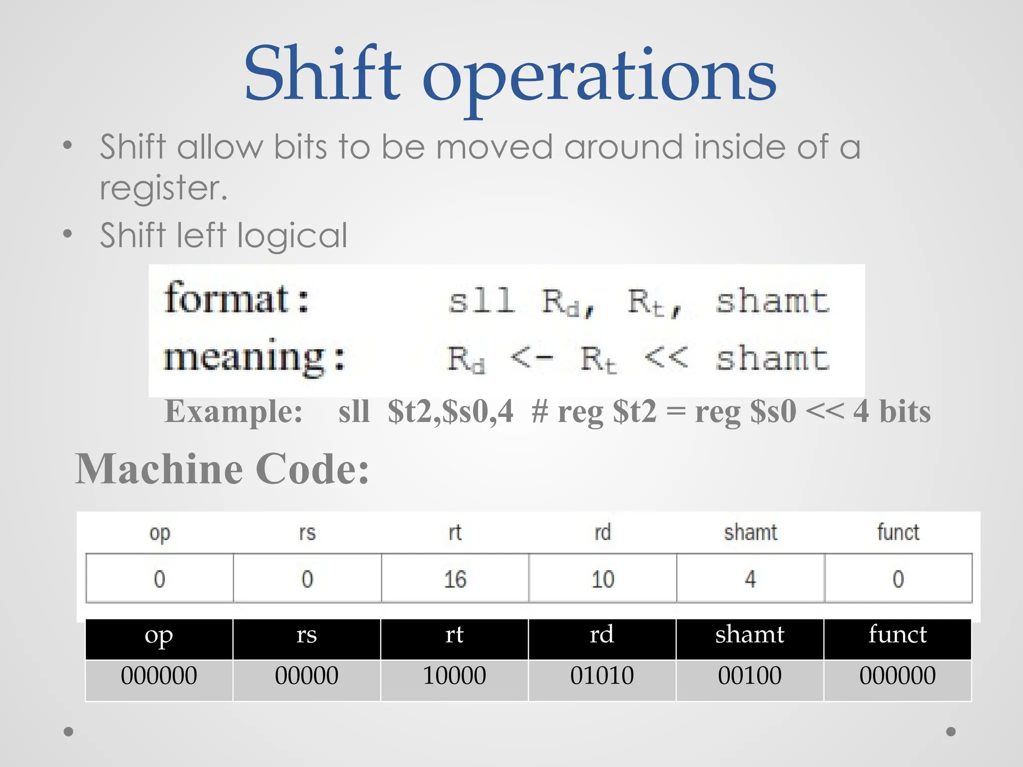
Loop: sll $t1,$s3,2 # Temp reg $t1 = i * 4
add $t1,$t1,$s6 # $t1 = address of save[i]
lw $t0,0($t1) # Temp reg $t0 = save[i]
bne $t0,$s5, Exit # go to Exit if save[i] ≠ k
addi $s3,$s3,1 # i = i + 1
j Loop # go to Loop
Exit:](https://image.slidesharecdn.com/unitica-241211143358-d81c66d9/75/Introduction-to-Computer-Architecture-unit-1-87-2048.jpg)
![Base or displacement
addressing mode
• Def:
o the operand is at the memory location whose address is the
sum of a register and a constant in the instruction
o Indirect addressing mode
• Ex:
o lw $s1, 20 ($s3) #$s1= Memory[$s3+20]
• Ilustration:](https://image.slidesharecdn.com/unitica-241211143358-d81c66d9/75/Introduction-to-Computer-Architecture-unit-1-91-2048.jpg)


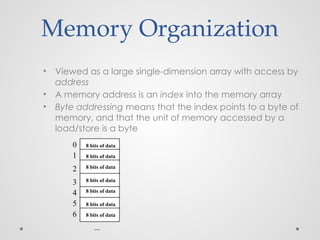
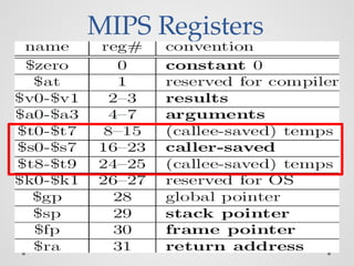
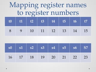
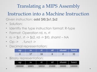
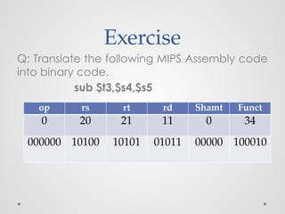
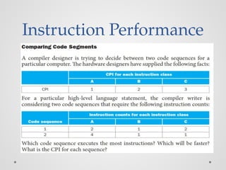
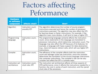
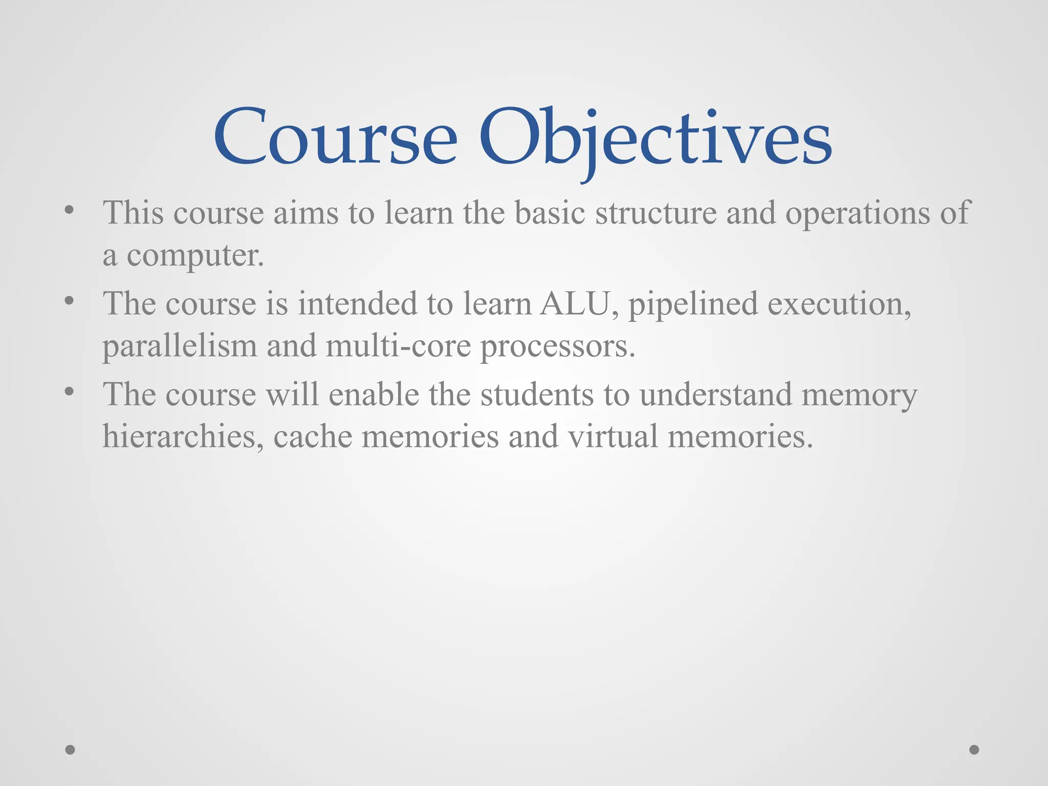
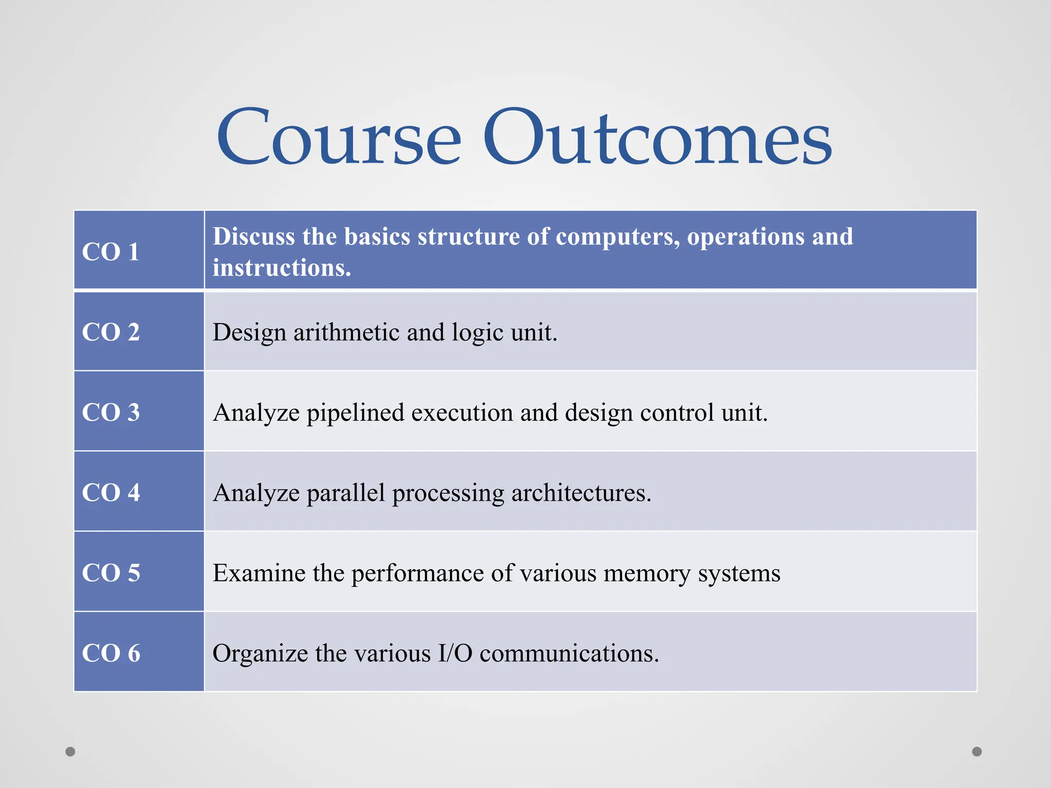
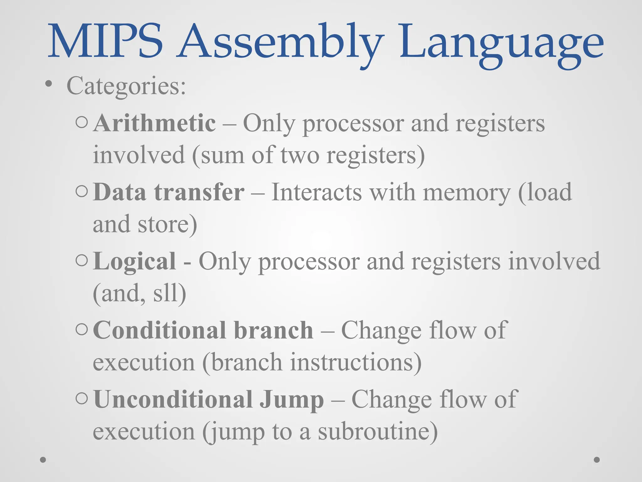
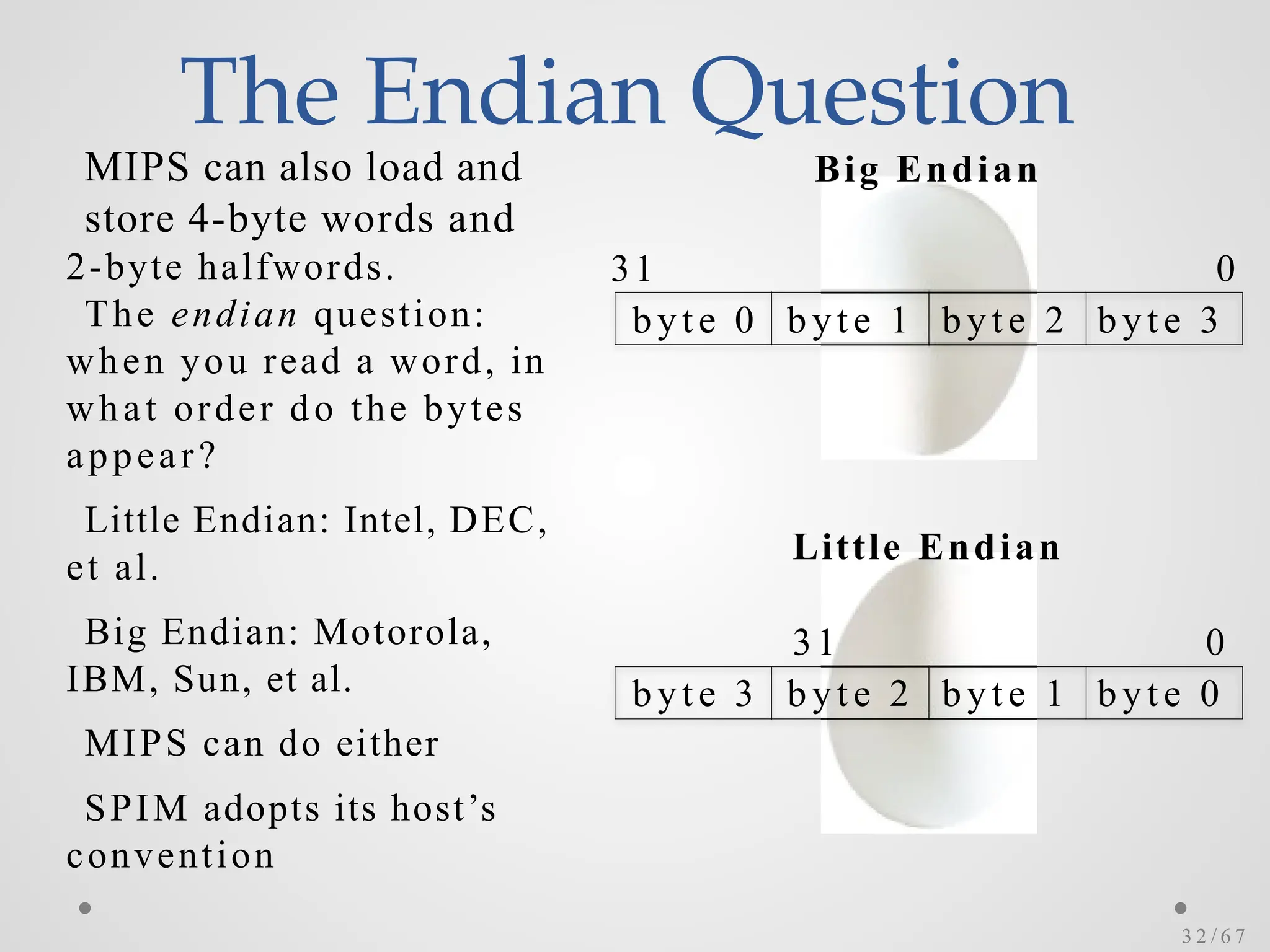
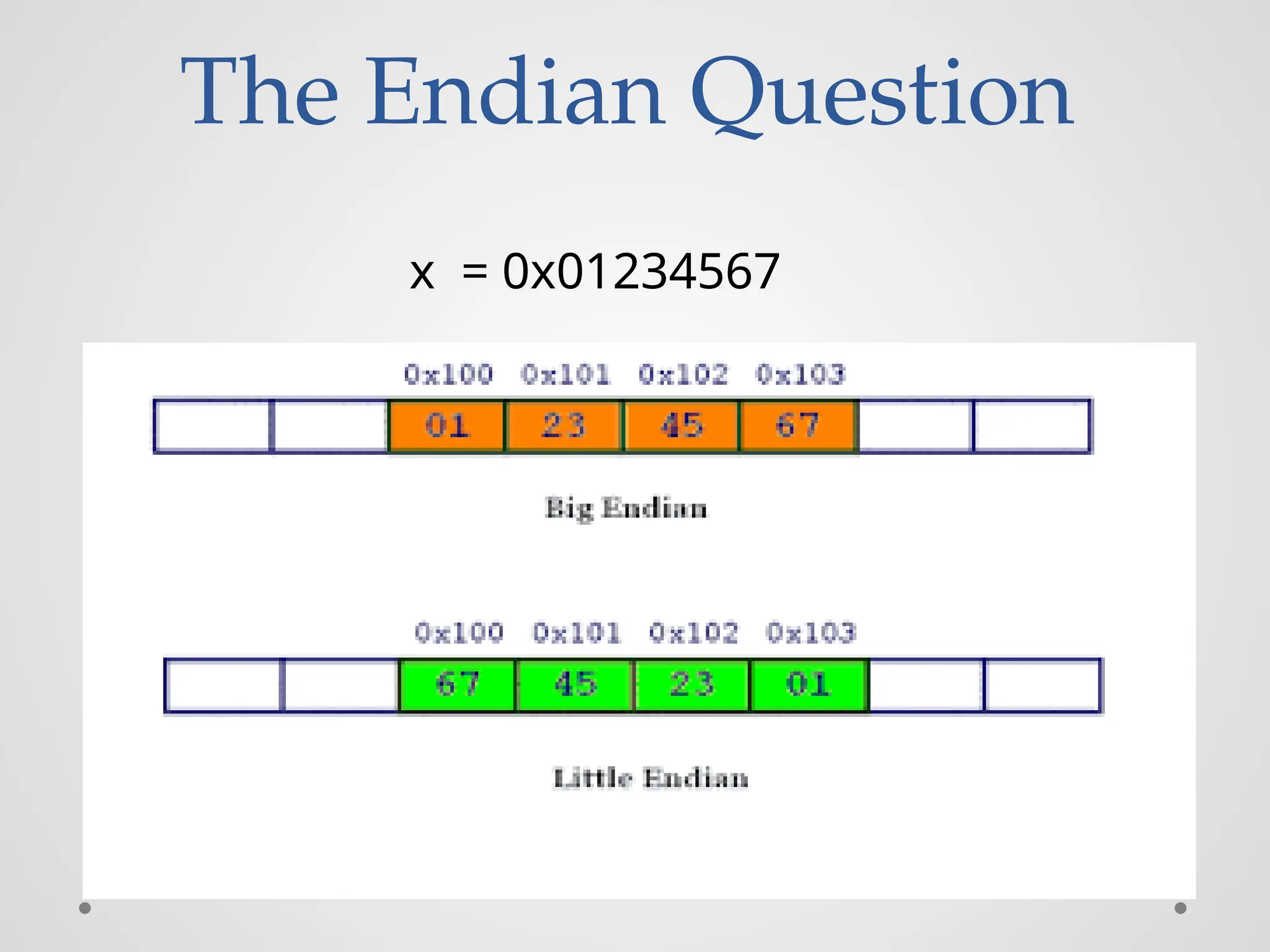
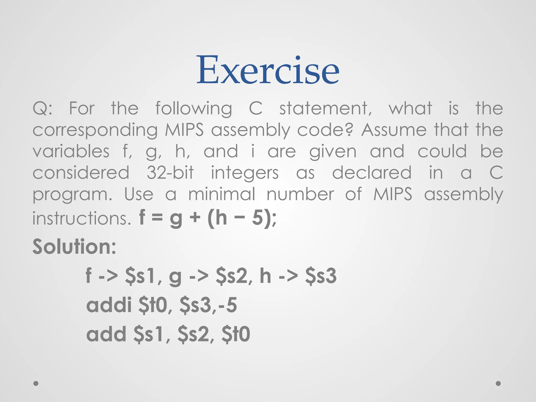
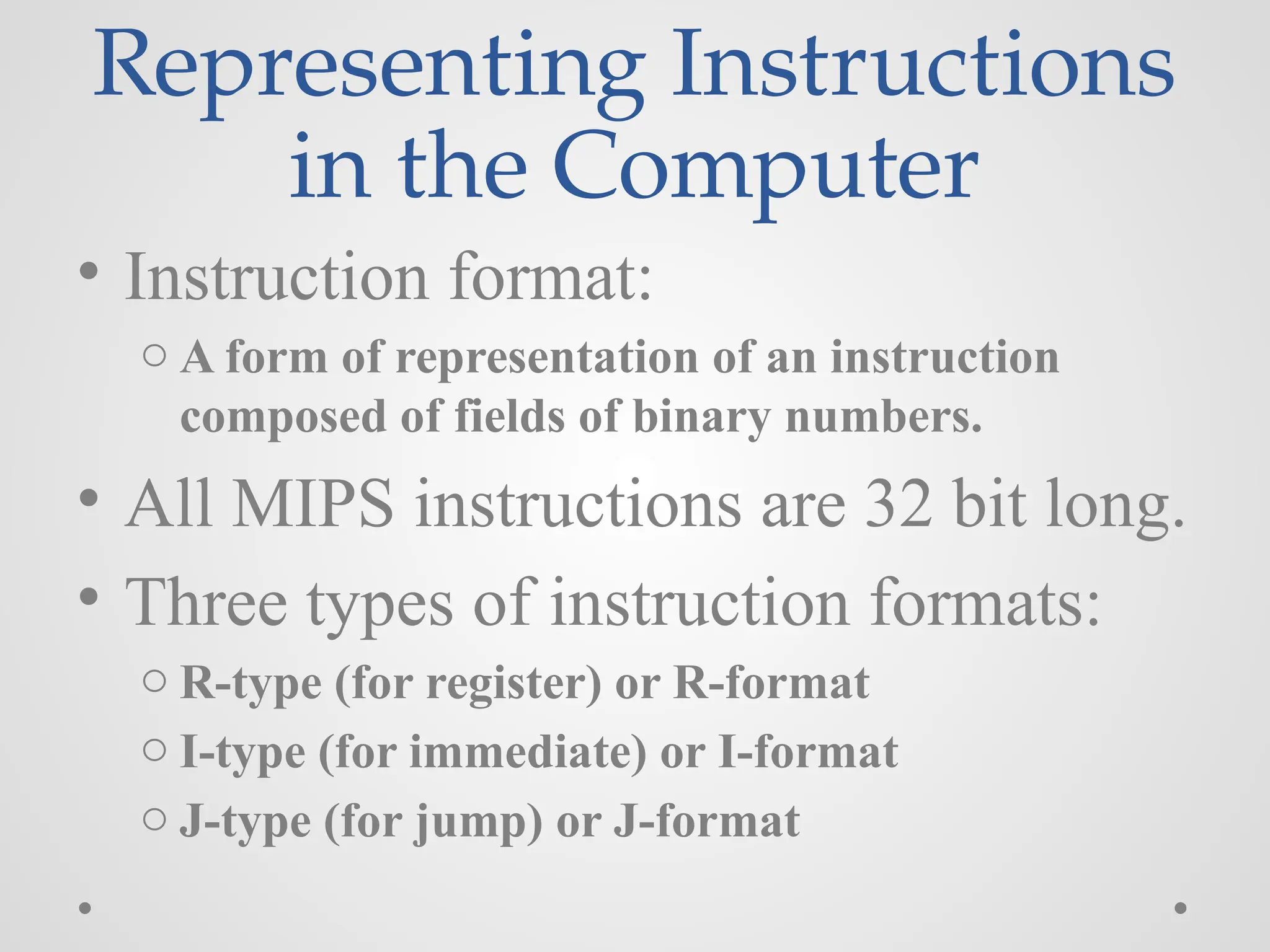
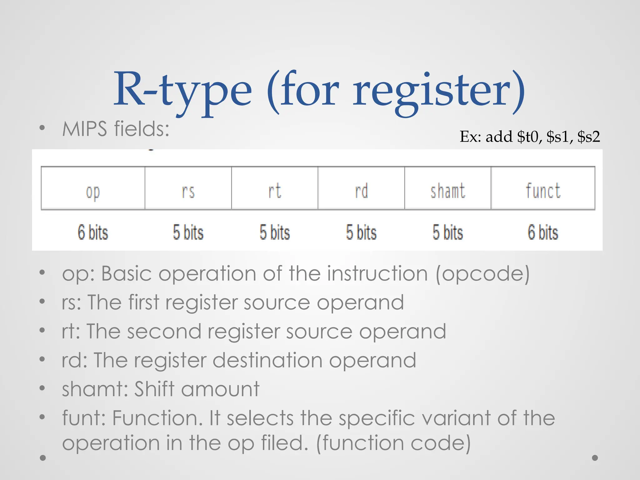
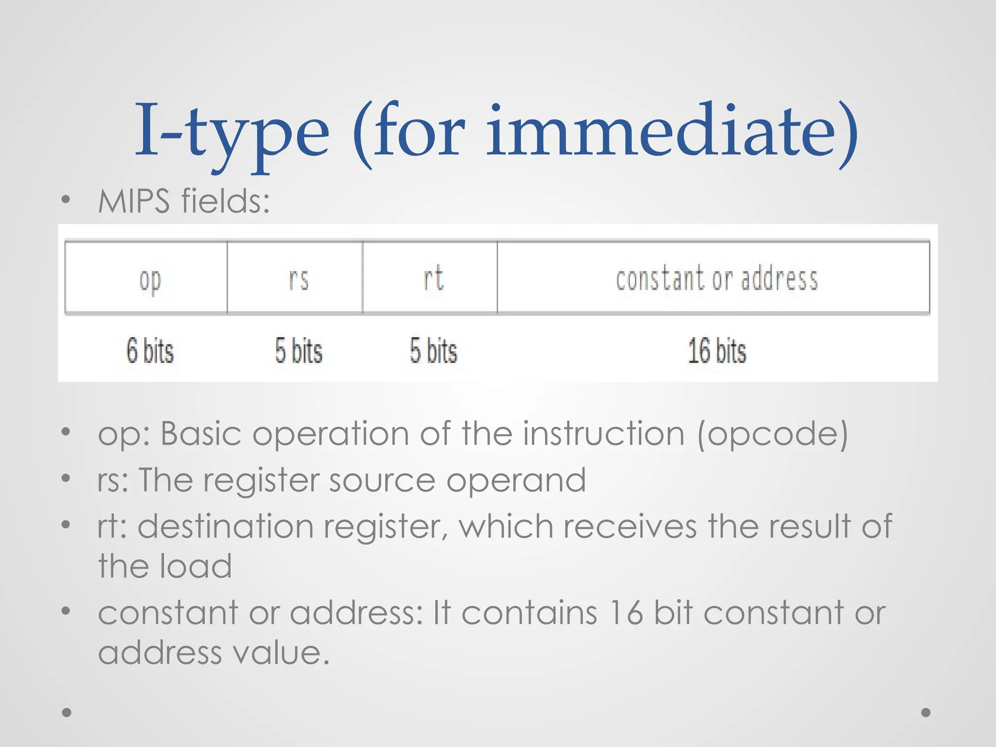
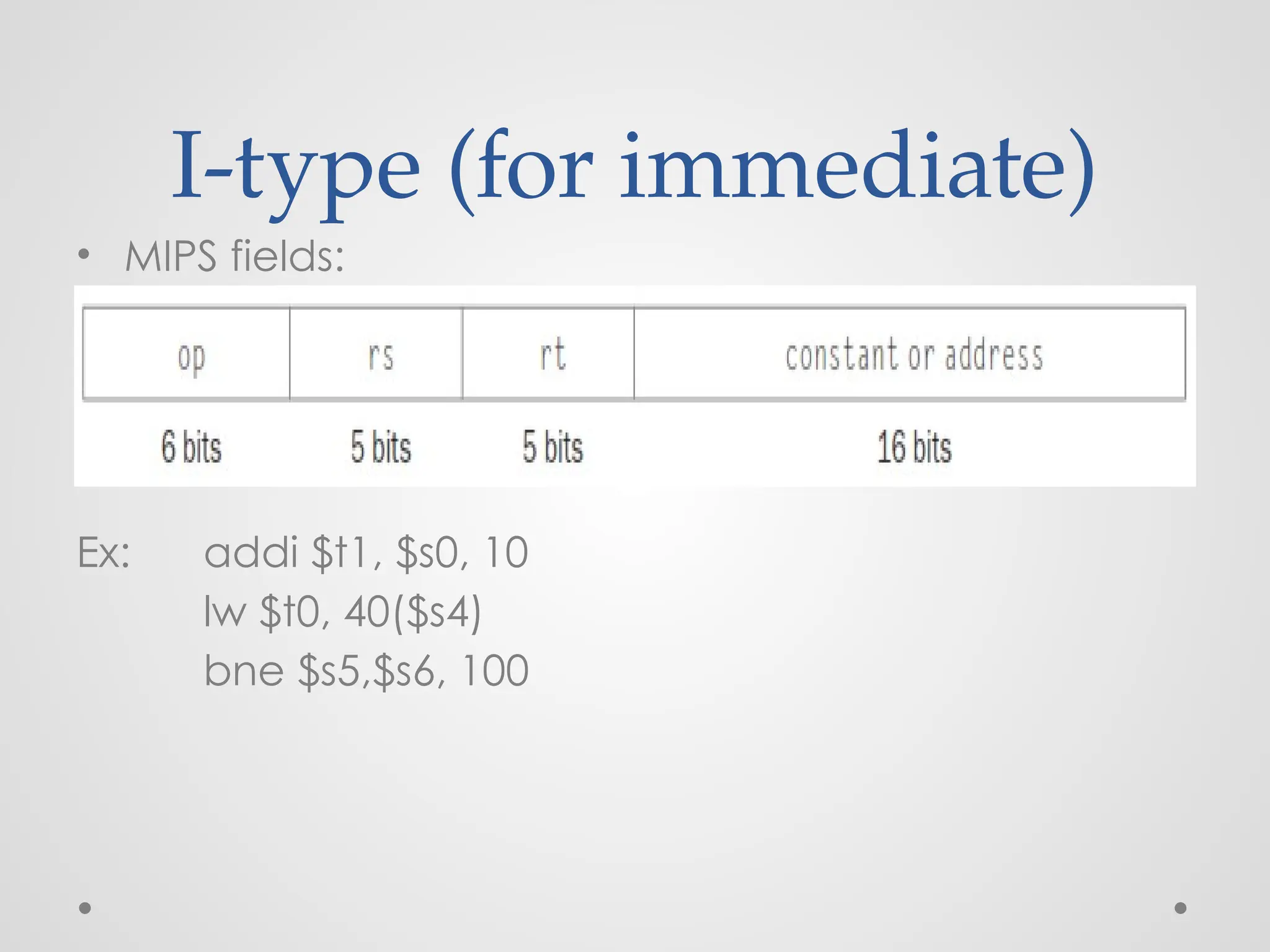
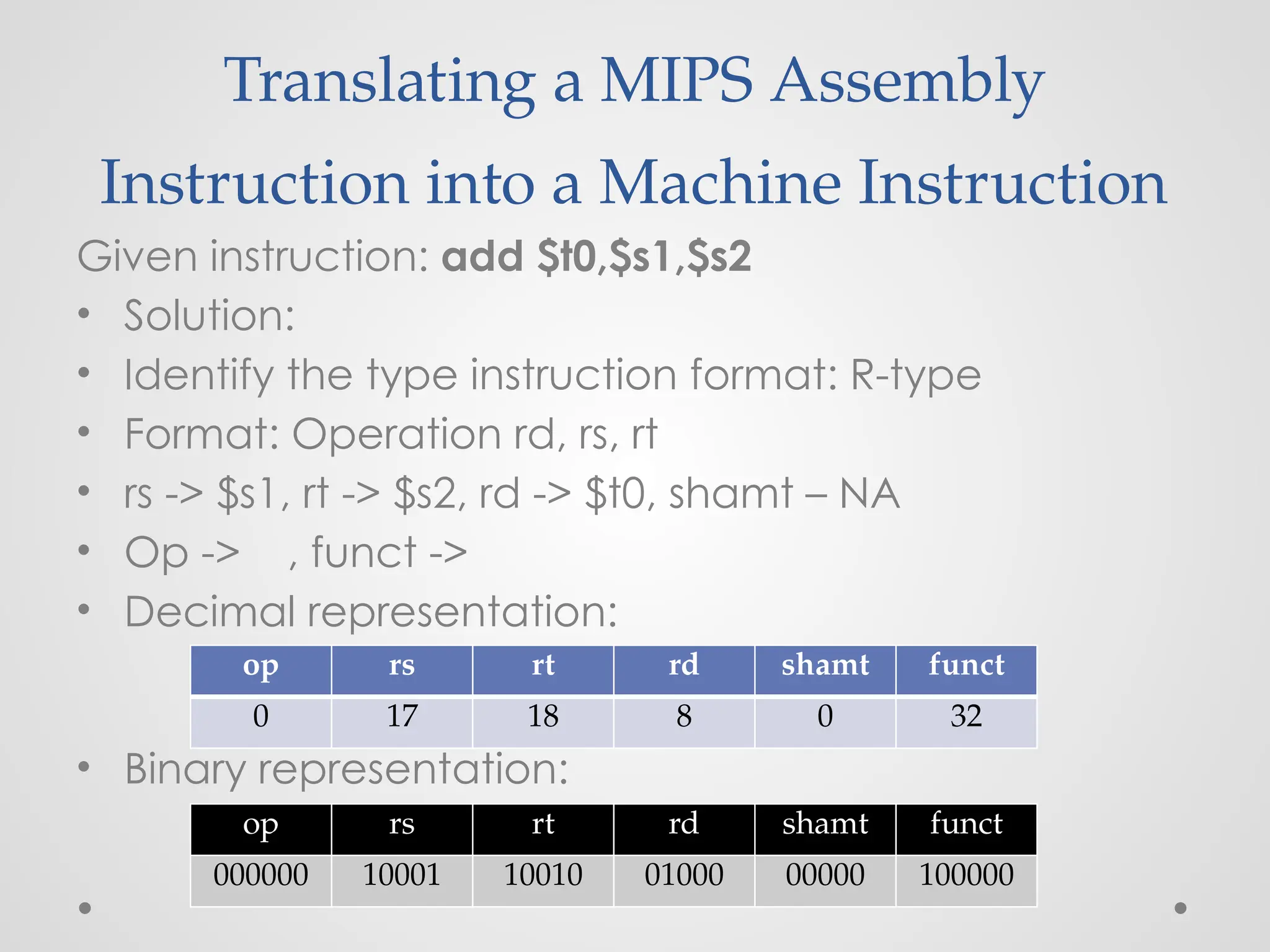
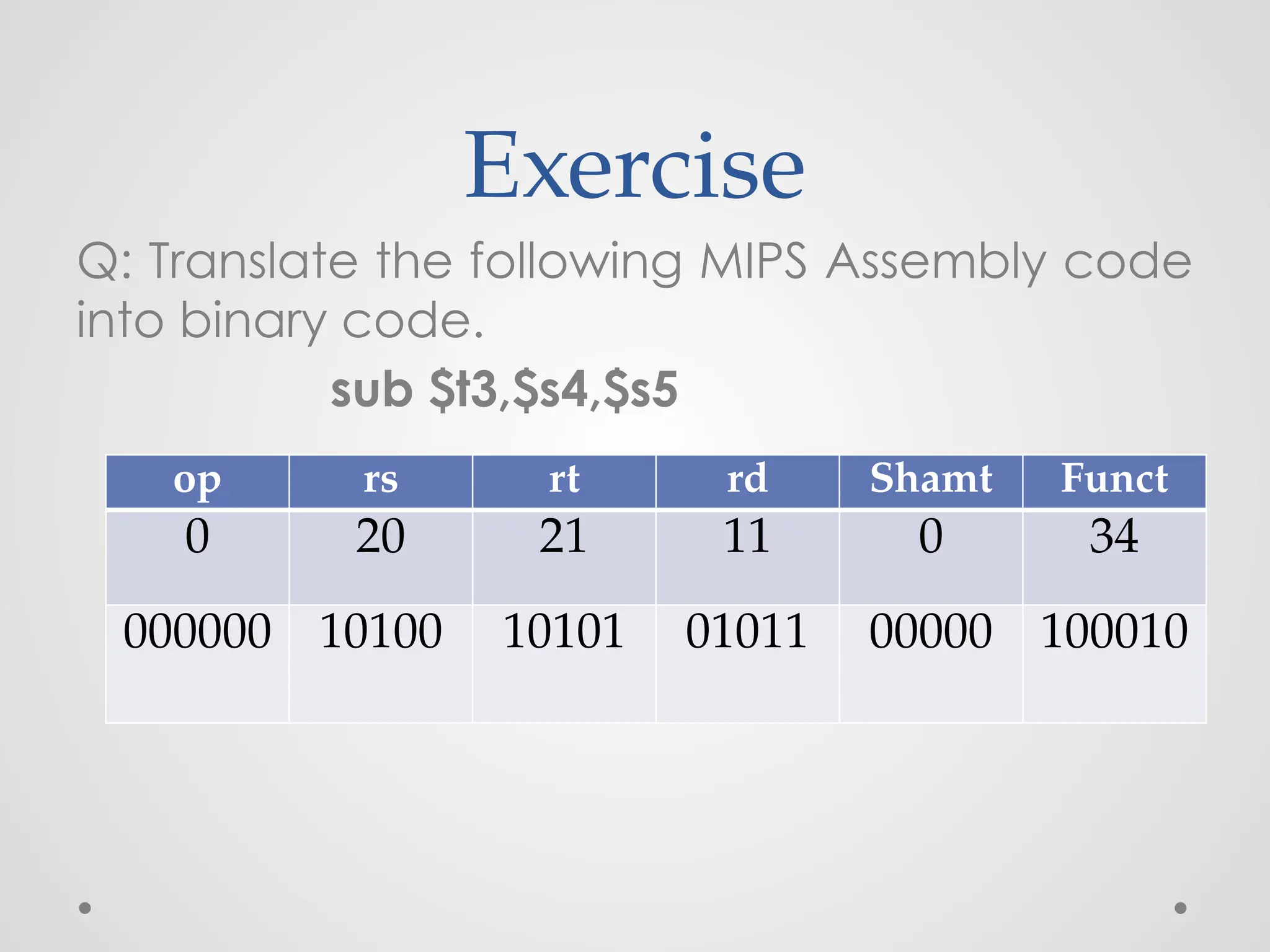
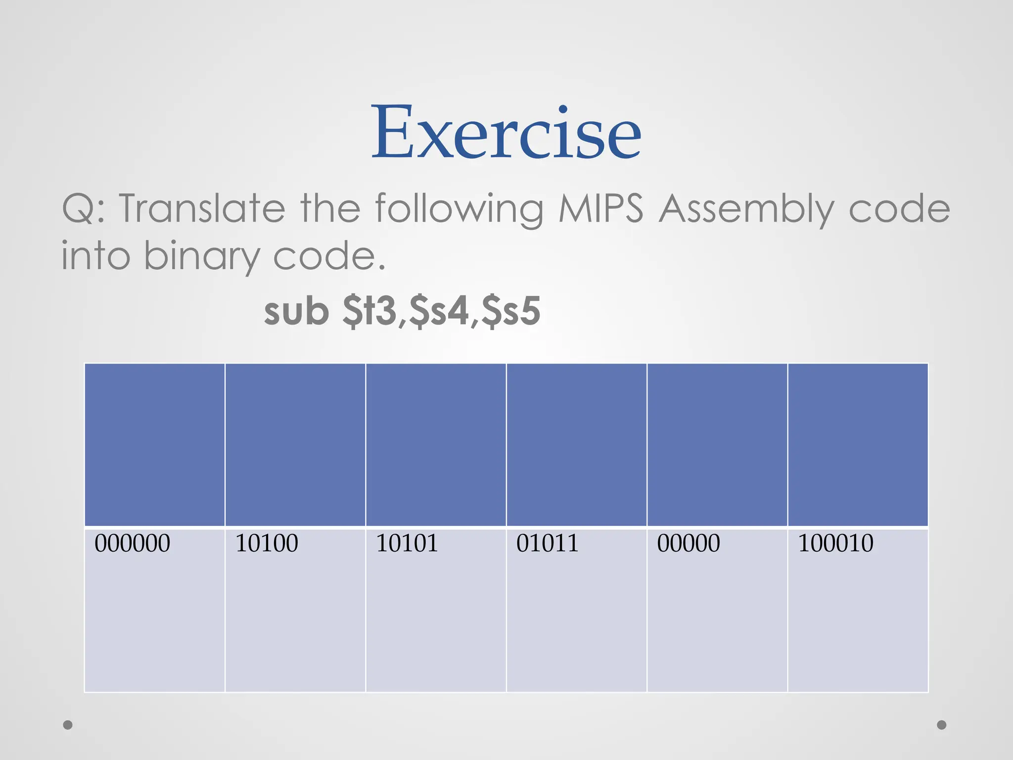
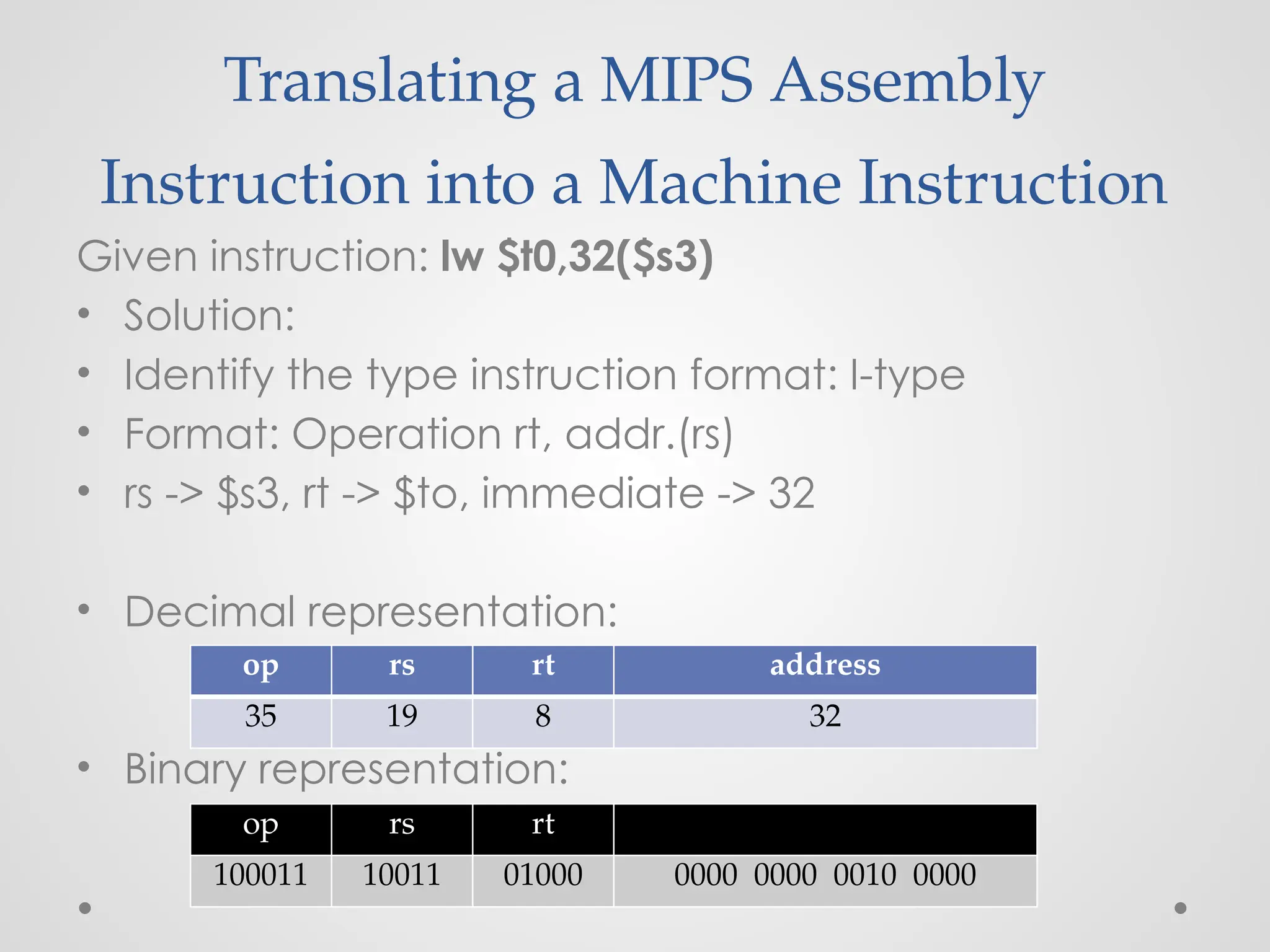
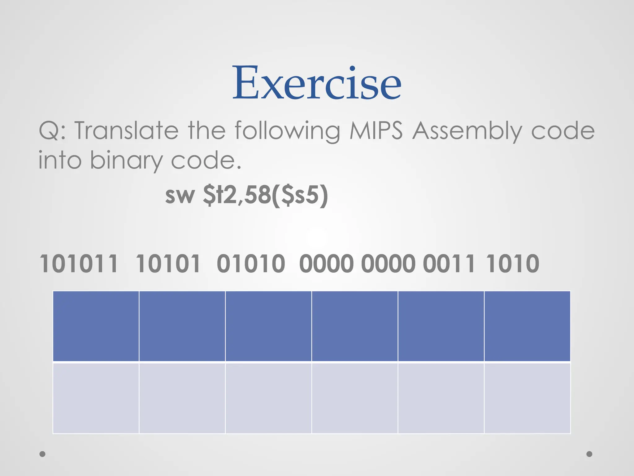
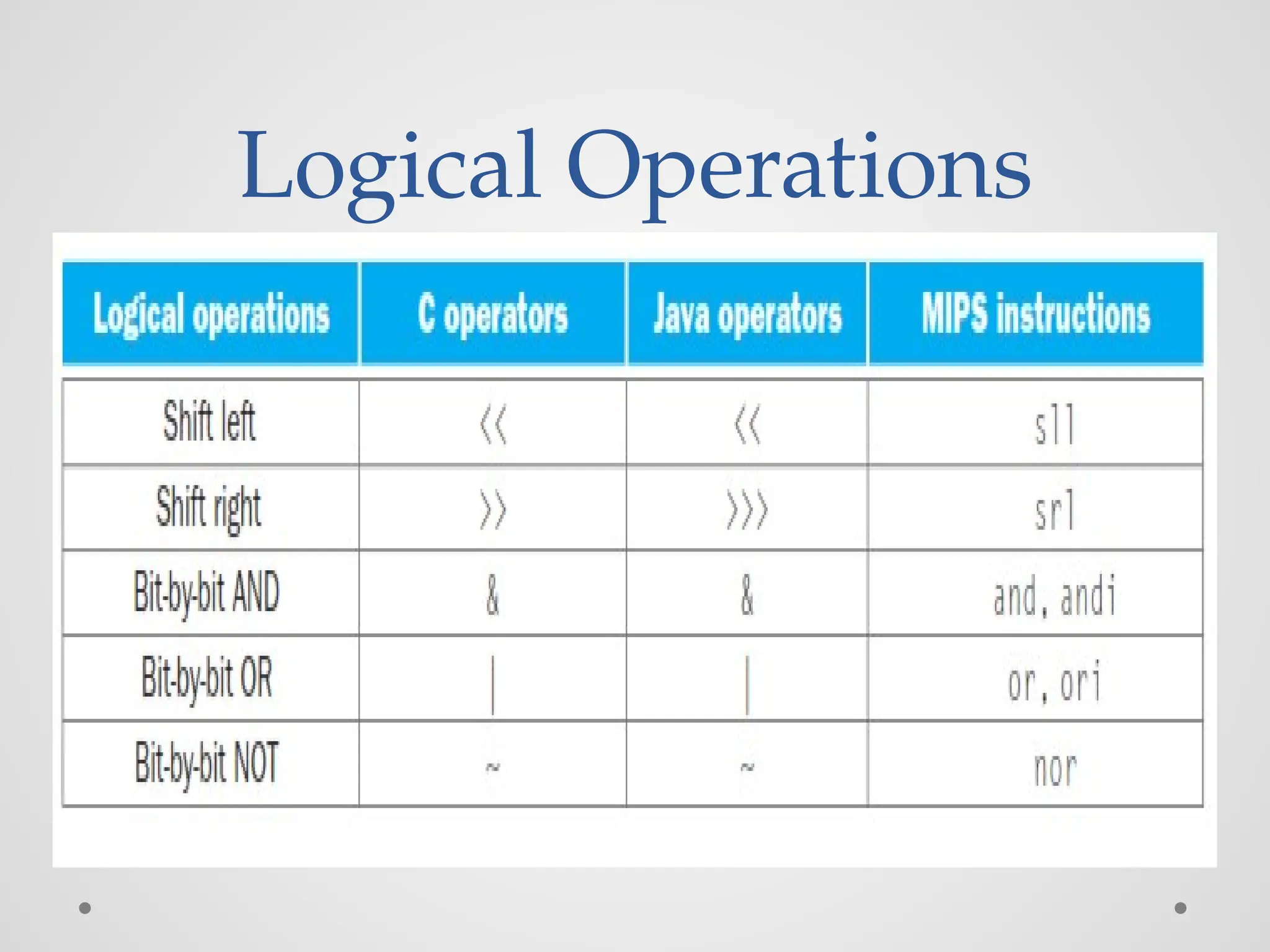
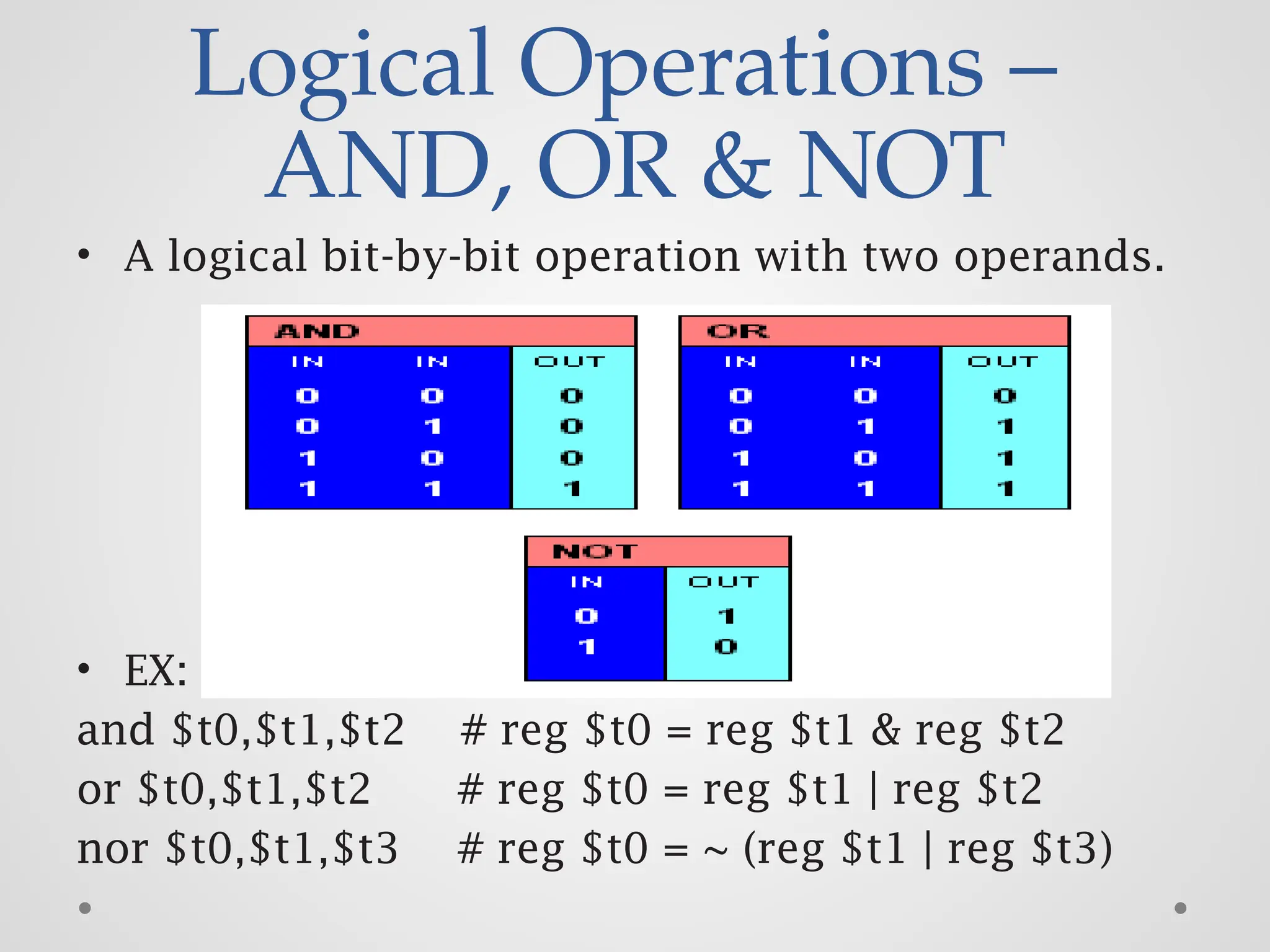
The document outlines the course objectives and outcomes for a computer architecture course at Velammal Engineering College's Computer Science and Engineering Department. It includes details on the syllabus covering topics such as computer structure, arithmetic for computers, processor control units, parallelism, and memory systems, as well as recommended textbooks and mips assembly language concepts. The document also explains instruction set architecture and offers examples related to MIPS assembly operations.


