Session-01 Introduction toComputer Networks
Session Topics:
Defination of Computer Networks,Uses.
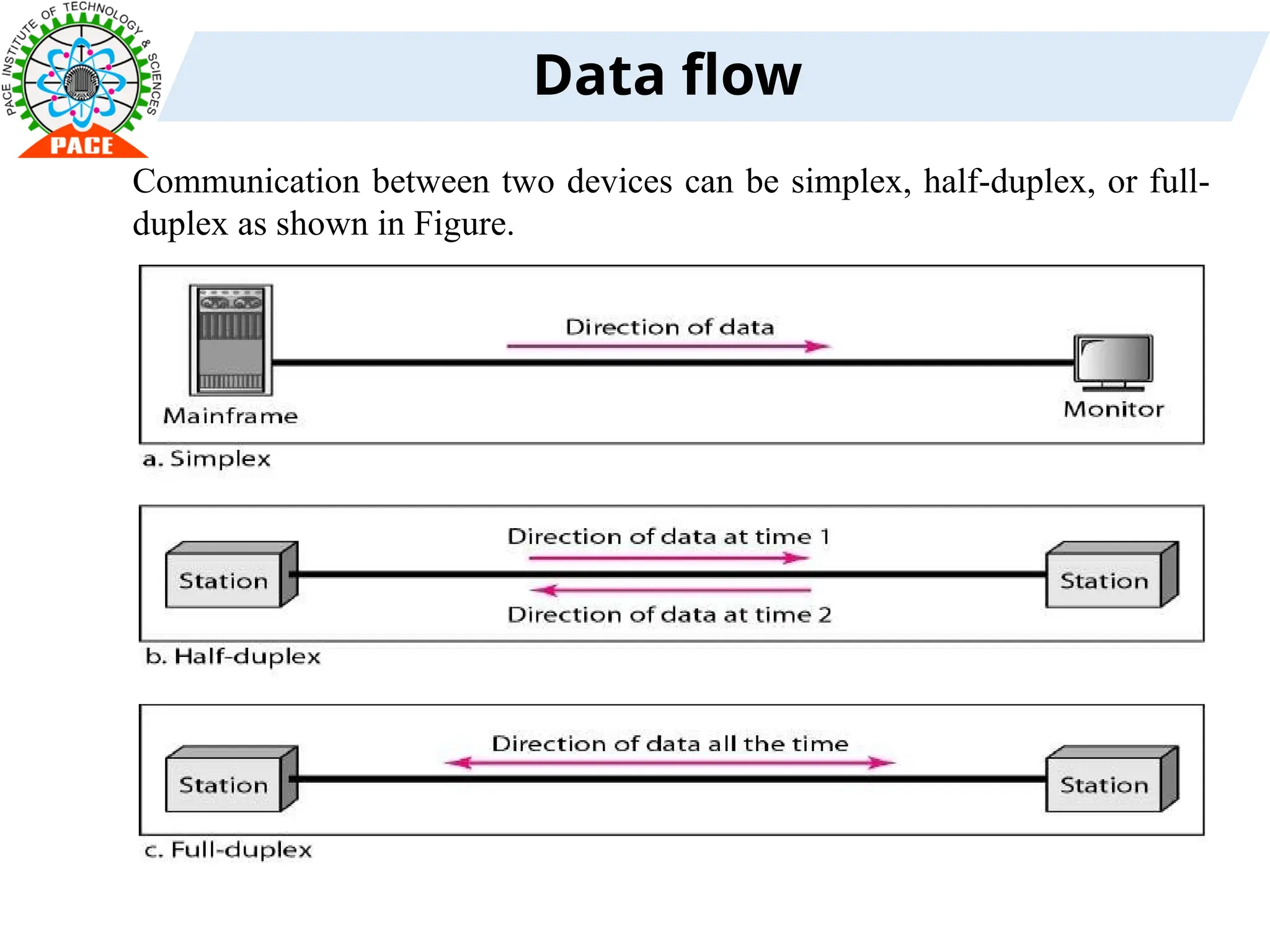
Components of data Communication, Data flow.
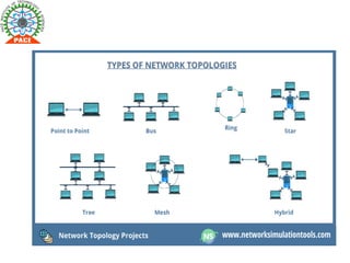
Network topologies:BUS,STAR,RING,MESH,TREE.
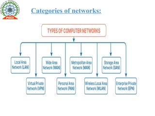
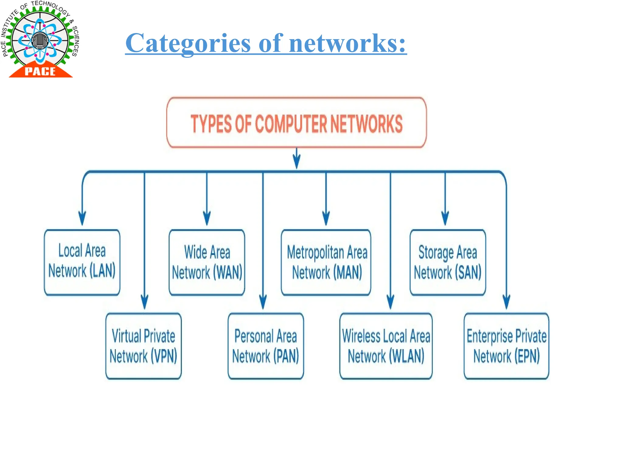
Categories of Networks- LAN ,MAN,WAN
Textbook: Andrew S Tanenbaum,“Computer Networks”,4 th edition,Pearson.2011
Page Numbers: 16-21
URL Link: https://www.geeksforgeeks.org/introduction-to-Computer Networks-
networks/
Material Link:
3.
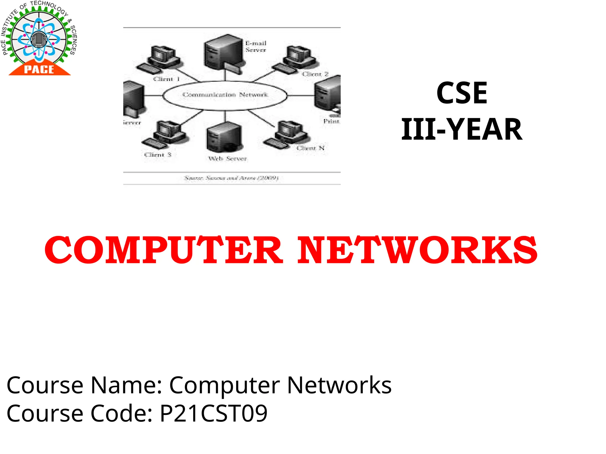
Definition of Computer
networks
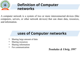
Acomputer network is a system of two or more interconnected devices (like
computers, servers, or other network devices) that can share data, resources,
and information.
uses of Computer networks
• Sharing large amount of data
• Sharing resources
• Sharing information
• For communication
Tsoukalas & Uhrig, 1997
4.
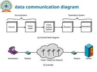
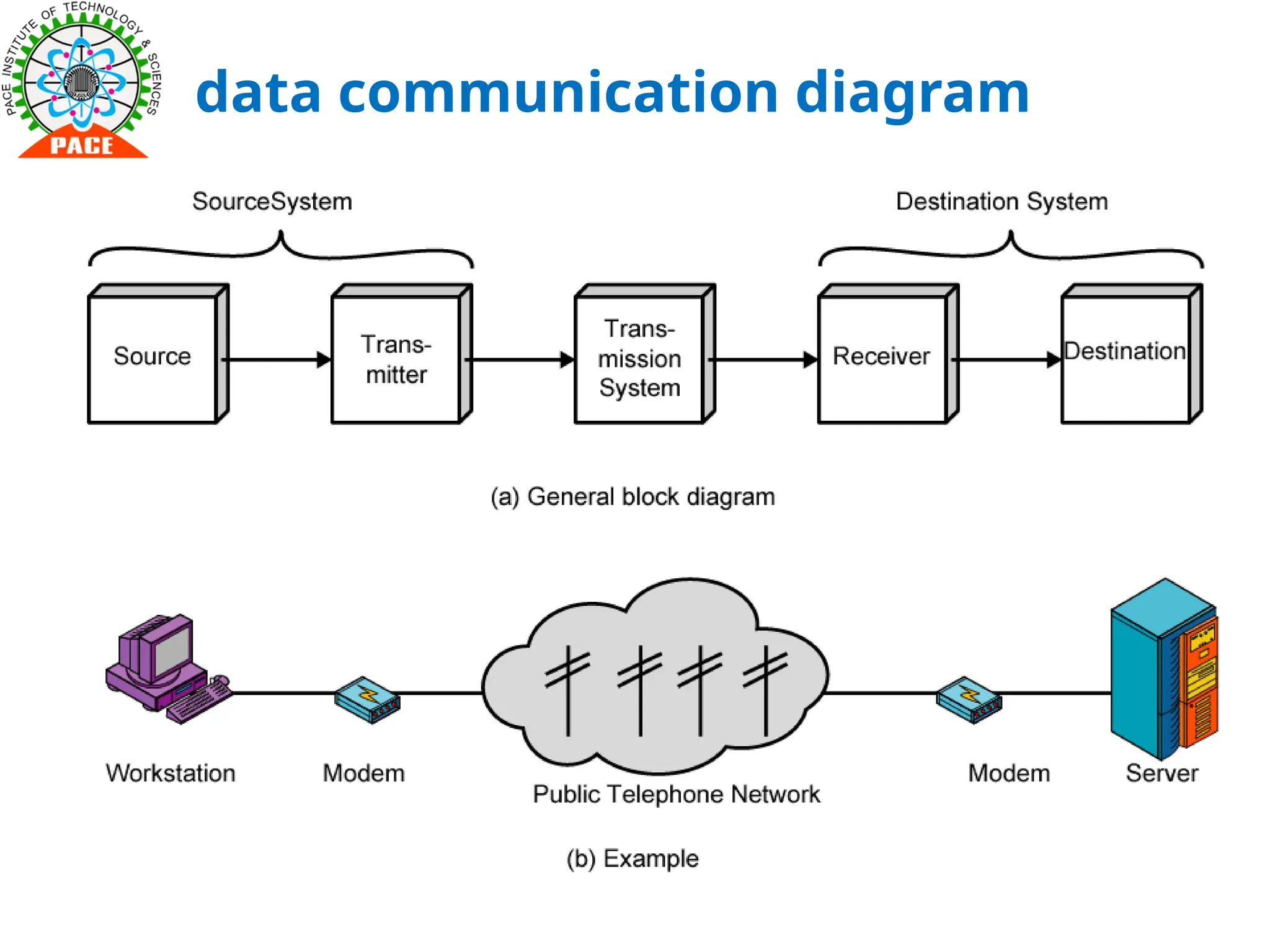
Components of data
communication
1.Message: The message is the information (data) to be communicated. Popular forms
of information include text, numbers, pictures, audio, and video.
2 Sender: The sender is the device that sends the data message. It can be a computer,
workstation, telephone handset, video camera, and so on.
3. Receiver: The receiver is the device that receives the message. It can be a computer,
workstation, telephone handset, television, and so on.
4. Transmission medium: The transmission medium is the physical path by which a
message travels from sender to receiver. Some examples of transmission media include
twisted-pair wire, coaxial cable, fiber-optic cable, and radio waves.
5. Protocol: A protocol is a set of rules that govern data communications. It represents
an agreement between the communicating devices. Without a protocol, two devices
may be connected but not communicating, just as a person speaking French cannot be
understood by a person who speaks only
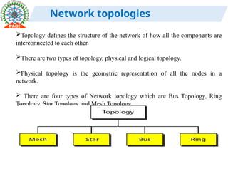
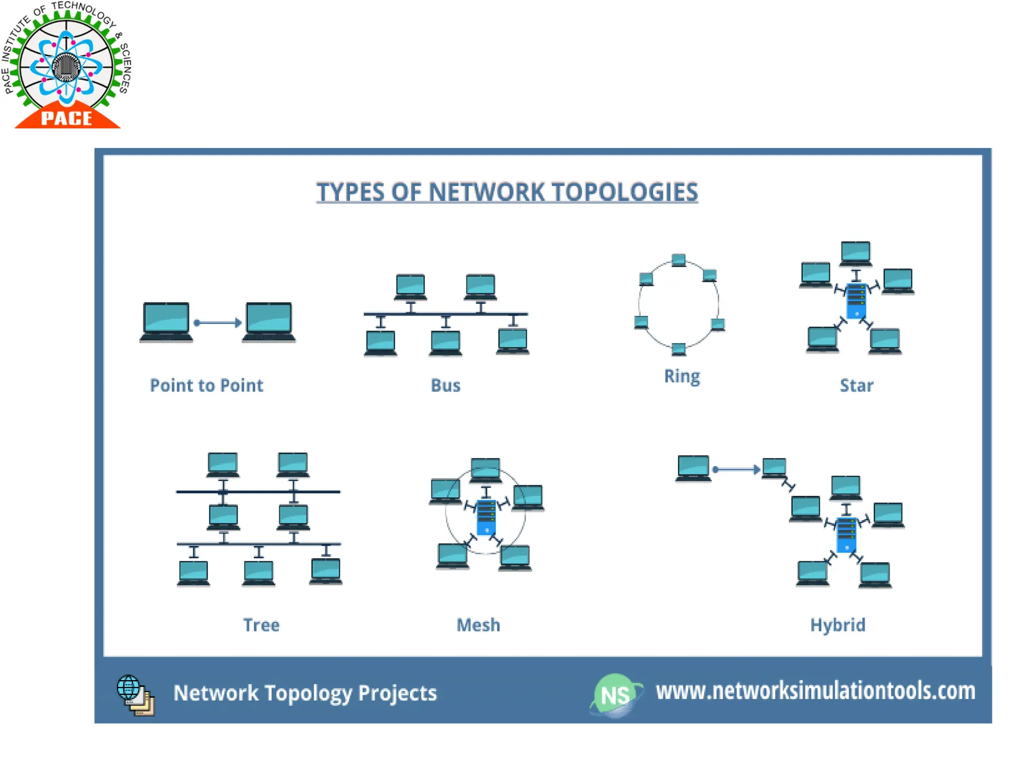
Network topologies
Topology definesthe structure of the network of how all the components are
interconnected to each other.
There are two types of topology, physical and logical topology.
Physical topology is the geometric representation of all the nodes in a
network.
There are four types of Network topology which are Bus Topology, Ring
Topology, Star Topology and Mesh Topology.
8.
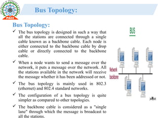
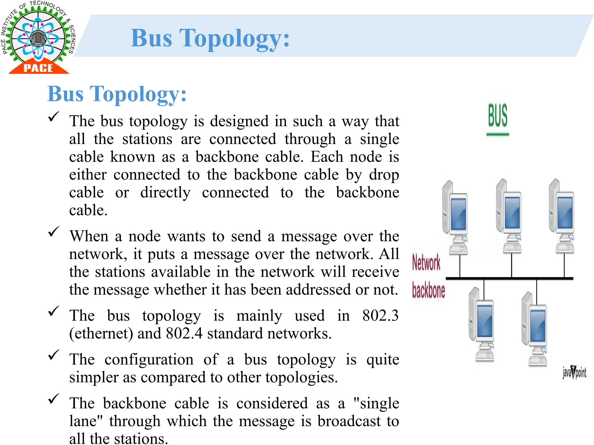
Bus Topology:
Thebus topology is designed in such a way that
all the stations are connected through a single
cable known as a backbone cable. Each node is
either connected to the backbone cable by drop
cable or directly connected to the backbone
cable.
When a node wants to send a message over the
network, it puts a message over the network. All
the stations available in the network will receive
the message whether it has been addressed or not.
The bus topology is mainly used in 802.3
(ethernet) and 802.4 standard networks.
The configuration of a bus topology is quite
simpler as compared to other topologies.
The backbone cable is considered as a "single
lane" through which the message is broadcast to
all the stations.
Bus Topology:
9.
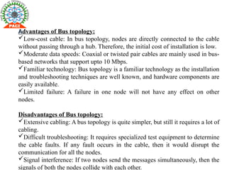
Advantages of Bustopology:
Low-cost cable: In bus topology, nodes are directly connected to the cable
without passing through a hub. Therefore, the initial cost of installation is low.
Moderate data speeds: Coaxial or twisted pair cables are mainly used in bus-
based networks that support upto 10 Mbps.
Familiar technology: Bus topology is a familiar technology as the installation
and troubleshooting techniques are well known, and hardware components are
easily available.
Limited failure: A failure in one node will not have any effect on other
nodes.
Disadvantages of Bus topology:
Extensive cabling: A bus topology is quite simpler, but still it requires a lot of
cabling.
Difficult troubleshooting: It requires specialized test equipment to determine
the cable faults. If any fault occurs in the cable, then it would disrupt the
communication for all the nodes.
Signal interference: If two nodes send the messages simultaneously, then the
signals of both the nodes collide with each other.
10.
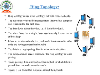
Ring Topology:
Ringtopology is like a bus topology, but with connected ends.
The node that receives the message from the previous computer
will retransmit to the next node.
The data flows in one direction, i.e., it is unidirectional.
The data flows in a single loop continuously known as an
endless loop.
It has no terminated ends, i.e., each node is connected to other
node and having no termination point.
The data in a ring topology flow in a clockwise direction.
The most common access method of the ring topology is token
passing.
Token passing: It is a network access method in which token is
passed from one node to another node.
Token: It is a frame that circulates around the network.
11.
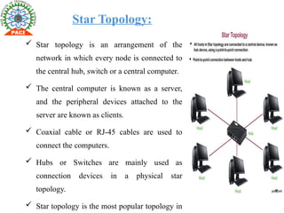
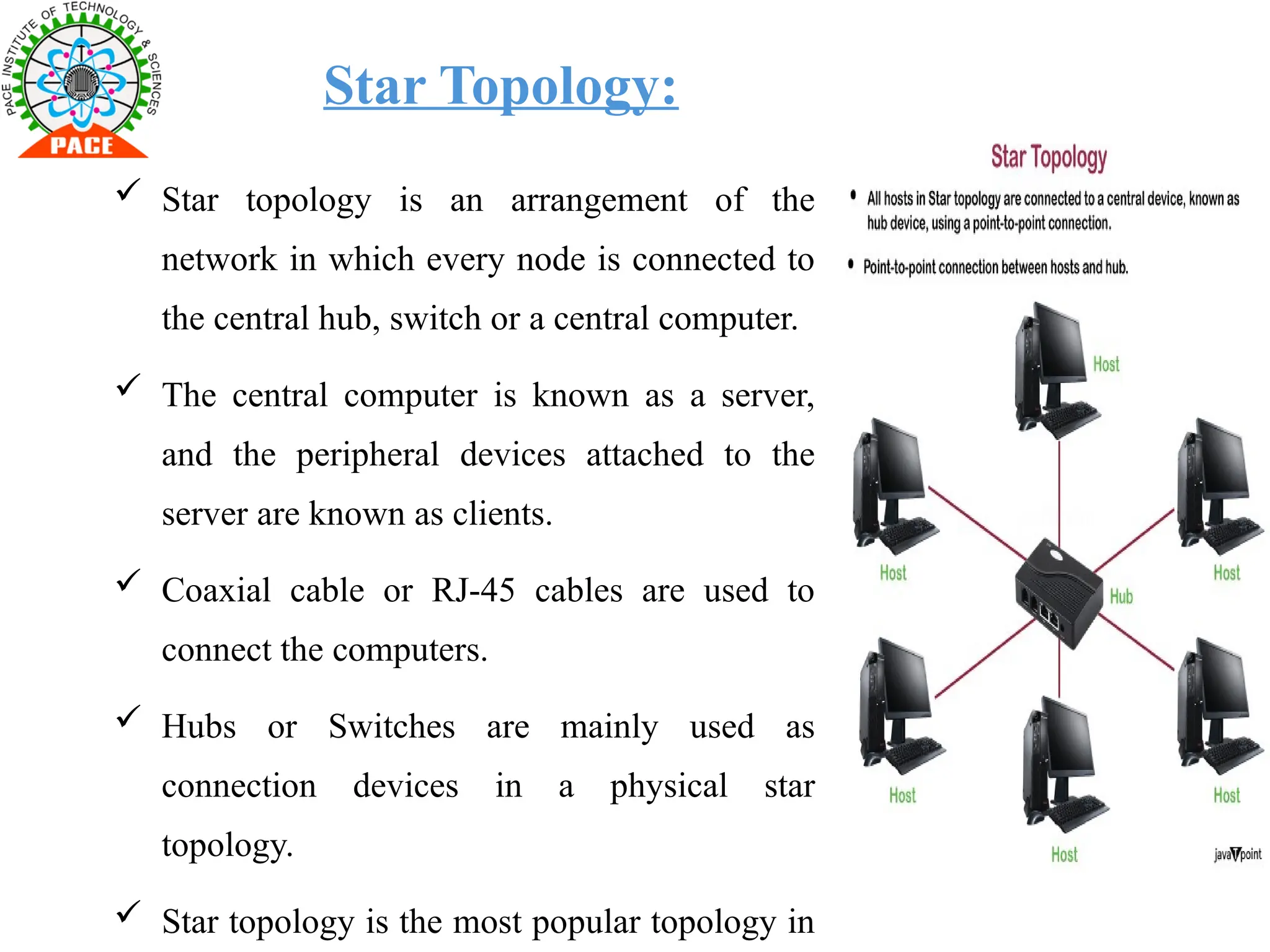
Star Topology:
Startopology is an arrangement of the
network in which every node is connected to
the central hub, switch or a central computer.
The central computer is known as a server,
and the peripheral devices attached to the
server are known as clients.
Coaxial cable or RJ-45 cables are used to
connect the computers.
Hubs or Switches are mainly used as
connection devices in a physical star
topology.
Star topology is the most popular topology in
12.
Advantages of Startopology:
Efficient troubleshooting: Troubleshooting is quite efficient in a star
topology as compared to bus topology. In a bus topology, the manager has to
inspect the kilometers of cable.
Network control: Complex network control features can be easily
implemented in the star topology. Any changes made in the star topology are
automatically accommodated.
Cost effective: Star topology networks are cost-effective as it uses
inexpensive coaxial cable.
High data speeds: It supports a bandwidth of approx 100Mbps. Ethernet
100BaseT is one of the most popular Star topology networks.
Disadvantages of Star topology:
A Central point of failure: If the central hub or switch goes down, then all
the connected nodes will not be able to communicate with each other.
Cable: Sometimes cable routing becomes difficult when a significant
amount of routing is required.
13.
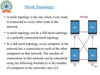
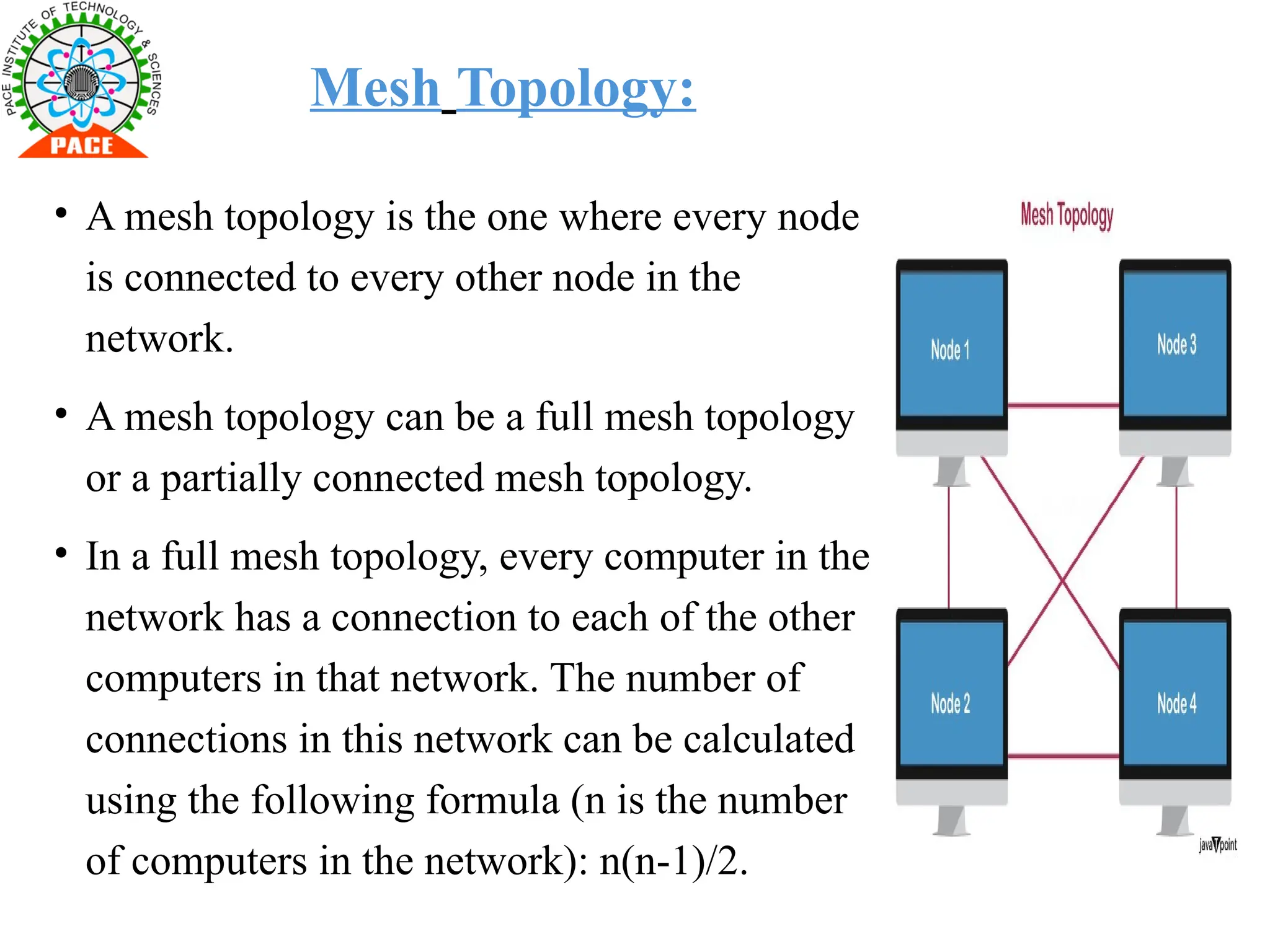
Mesh Topology:
• Amesh topology is the one where every node
is connected to every other node in the
network.
• A mesh topology can be a full mesh topology
or a partially connected mesh topology.
• In a full mesh topology, every computer in the
network has a connection to each of the other
computers in that network. The number of
connections in this network can be calculated
using the following formula (n is the number
of computers in the network): n(n-1)/2.
14.
Other Topologies:
• Pointto Point Topology – Point to Point topology is the simplest
topology that connects two nodes directly together with a common link.
• Tree Topology – In this type of topology nodes are connected in the
form of a tree. The function of the central node in this topology may be
distributed
• Line Topology – in this topology all the nodes are connected in a
straight line
• Hybrid Topology – When two more types of topologies combine
together, they form a Hybrid topology
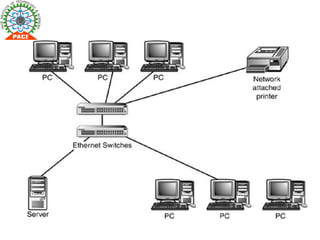
Local area network(LAN):
1. Local area network (LAN):
• A local area network, or LAN, is the most common network type. It allows
users to connect within a short distance in a common area. Once they
connect, users have access to the same resources. For example, you might
use a LAN when you connect your laptop to the internet at your home and
print a document from a printer on the same network.
19.
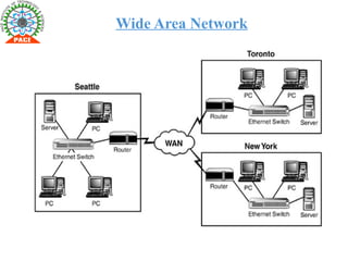
Wide Area Network
•A WAN is a network that spans more than one geographical location
often connecting separated LANs. WANs are slower than LANs and
often require additional and costly hardware such as routers, dedicated
leased lines, and complicated implementation procedures.
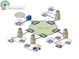
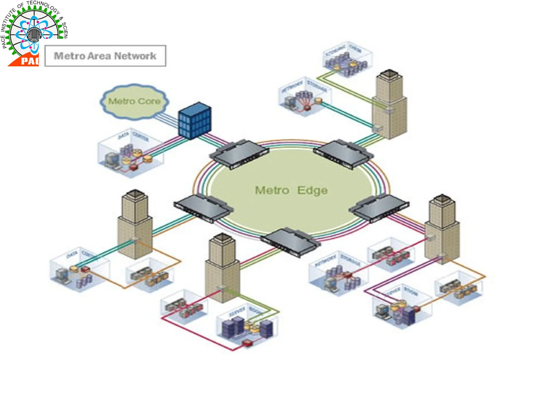
Metropolitan Area Network(MAN):
•A network spanning a physical area larger than a LAN but smaller than
a WAN, such as a city. A MAN is typically owned an operated by a
single entity such as a government body or large corporation.
23.
Check Knowledge: Session1
Q1. A network that contains multiple hubs is most likely configured in a _ _ __ _ _
_ topology .
a) bus
b) mesh
c) star
d) tree
Q2. Security and privacy are less of an issue for devices in a _ _ _ _ _ _ _ _topology
a) bus
b) mesh
c) star
d) tree
Q3. In which data flow model communication is possible on bothe sides at a time.
A) Simplex.
B) Half duplx.
C) Full duplex.
D) None of these.
Students Understanding
Verification Questions
(Objective, from the lecture)
During the session randomly
(at any point of time to make
the student alert)
Session-02 Reference Model
SessionTopics:
The ISO-OSI Reference Model:Pyshscial layer,Data link
layer,Network layer.
Session layer,Presentation layer,Application layer.
The TCP/IP Reference Model.
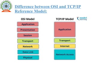
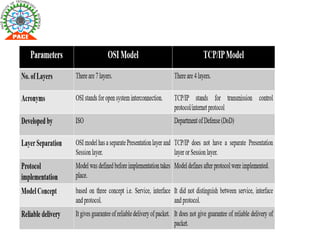
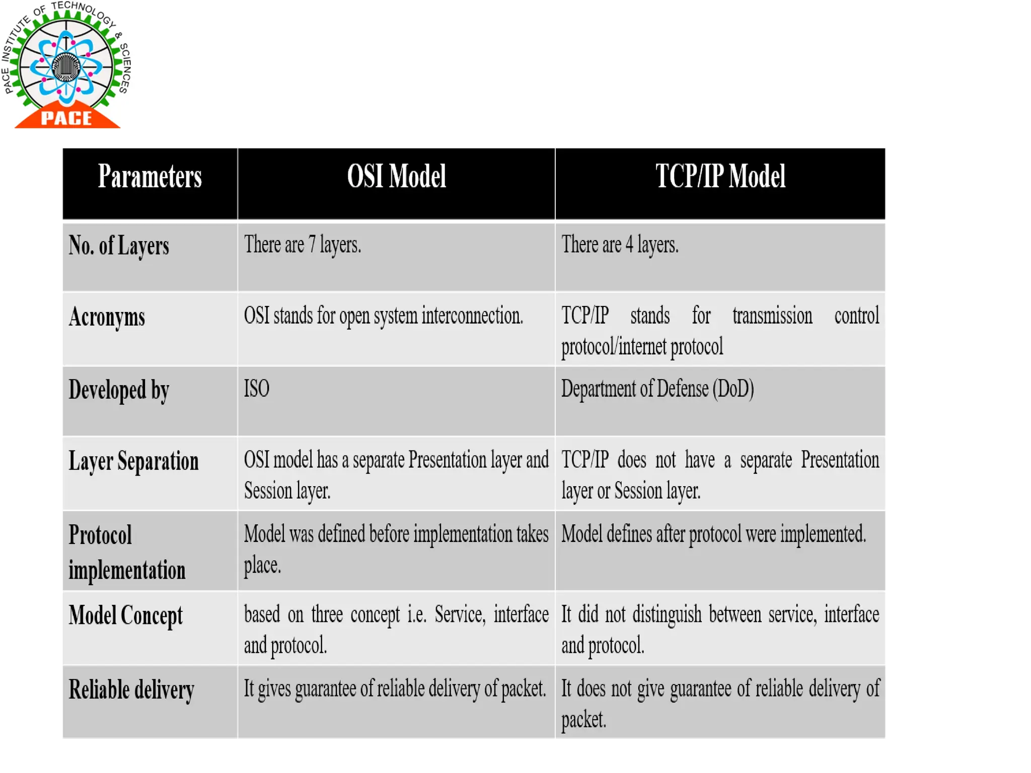
A Comparison of the OSI and TCP/IP Reference Models.
Textbook: Andrew S Tanenbaum,“Computer Networks”,4 th edition,Pearson.2011
Page Numbers: 37-44
URL Link: https://www.geeksforgeeks.org/Reference Model-to-Computer
Networks-networks/
Material Link:
26.
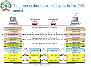
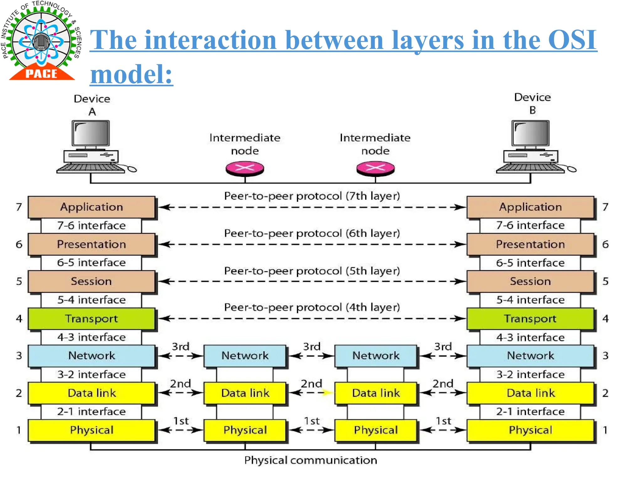
ISO-OSI MODEL:
• TheISO-OSI model, or OSI model (Open Systems Interconnection model),
is a conceptual framework that standardizes the functions of a
telecommunication or computing system into seven distinct layers.
• Each layer represents a specific set of functions and protocols that enable
devices to communicate over a network. The model was developed by the
International Organization for Standardization (ISO) to promote
interoperability between different systems and vendors.
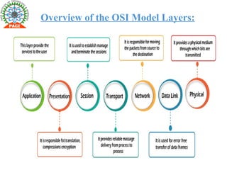
OSI Model layerscontd..:
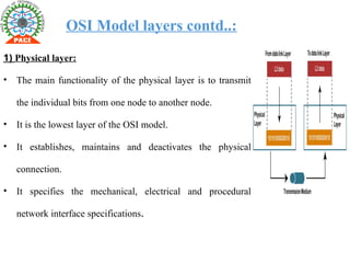
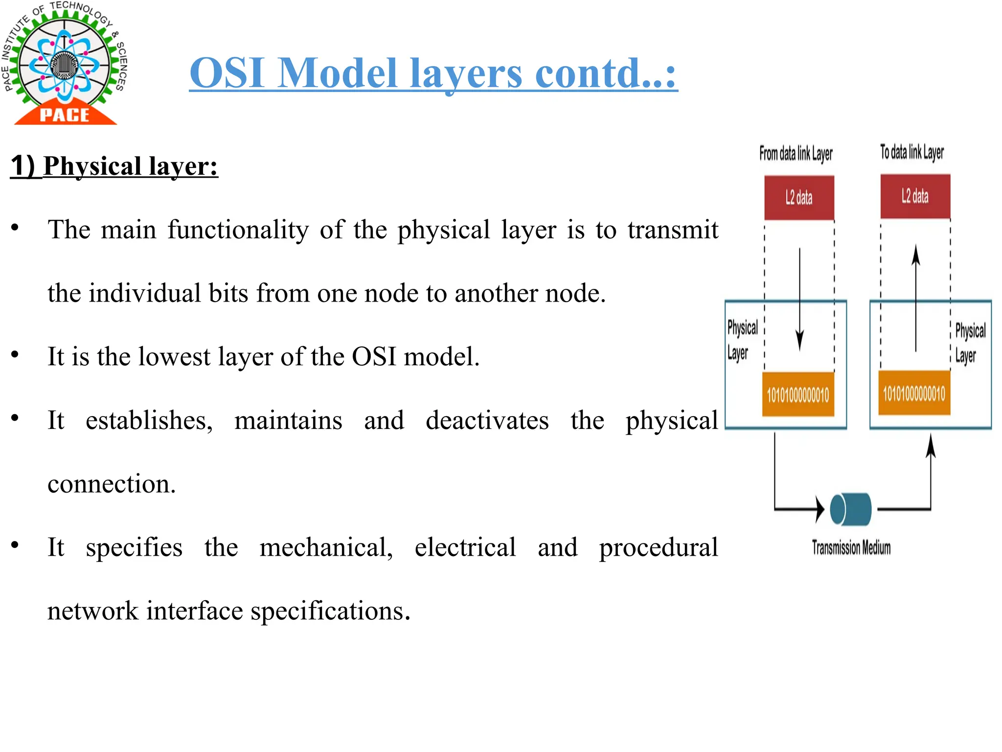
1) Physical layer:
• The main functionality of the physical layer is to transmit
the individual bits from one node to another node.
• It is the lowest layer of the OSI model.
• It establishes, maintains and deactivates the physical
connection.
• It specifies the mechanical, electrical and procedural
network interface specifications.
29.
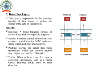
2) Data-Link Layer:
This layer is responsible for the error-free
transfer of data frames. It defines the
format of the data on the network.
FRAME:
Structure: A frame typically consists of
several fields that serve specific purposes:
Header: Contains control information such
as source and destination MAC addresses,
frame length, and error checking bits.
Payload: Carries the actual data being
transmitted, which can include packets
from higher layers of the OSI model.
Trailer: Often includes error detection or
correction information, such as a Frame
Check Sequence (FCS) used for error
detection.
30.
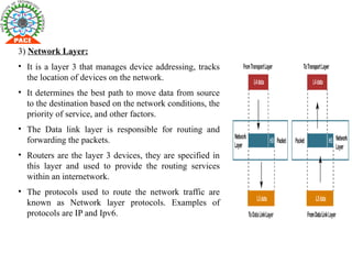
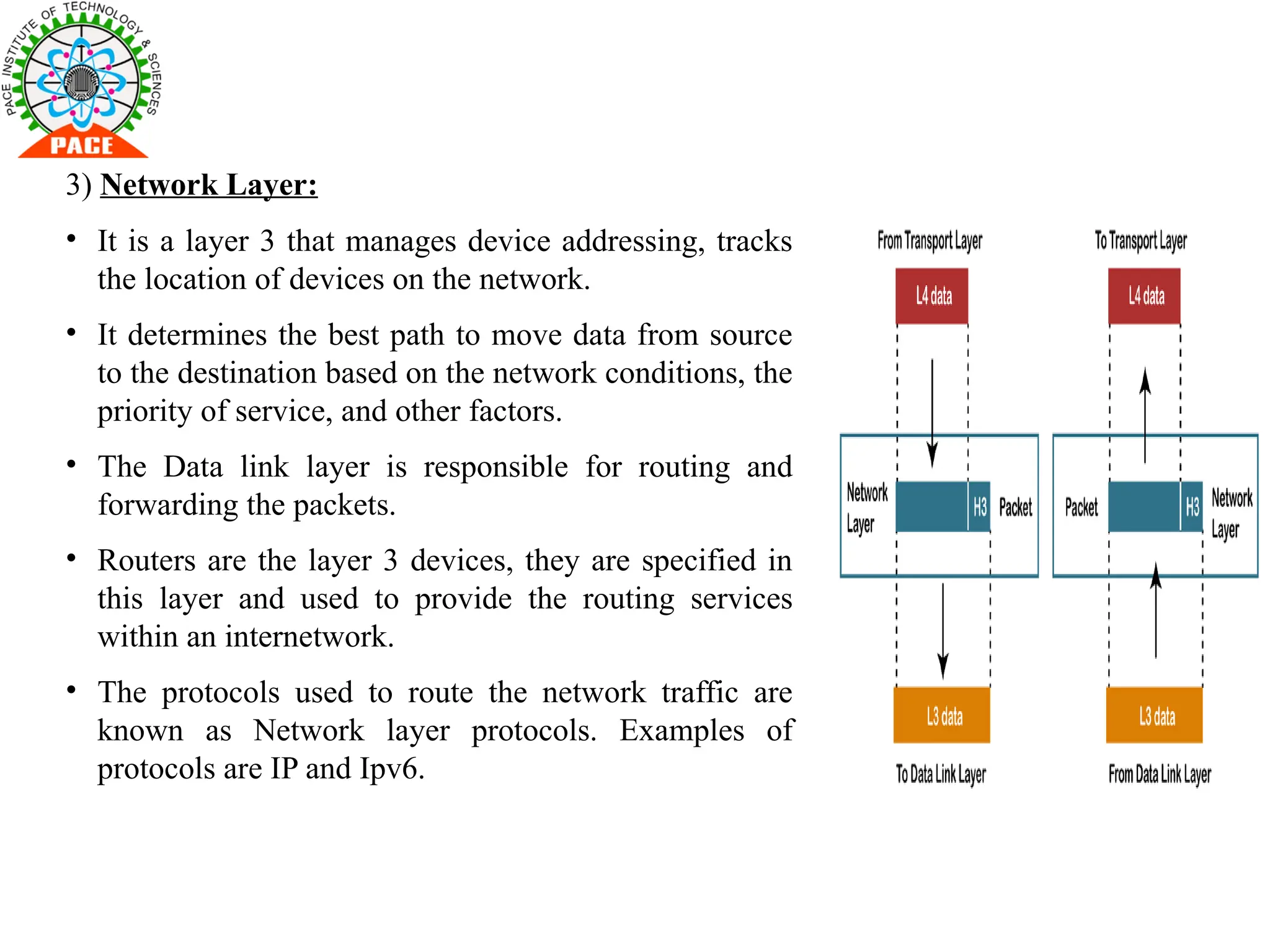
3) Network Layer:
•It is a layer 3 that manages device addressing, tracks
the location of devices on the network.
• It determines the best path to move data from source
to the destination based on the network conditions, the
priority of service, and other factors.
• The Data link layer is responsible for routing and
forwarding the packets.
• Routers are the layer 3 devices, they are specified in
this layer and used to provide the routing services
within an internetwork.
• The protocols used to route the network traffic are
known as Network layer protocols. Examples of
protocols are IP and Ipv6.
31.
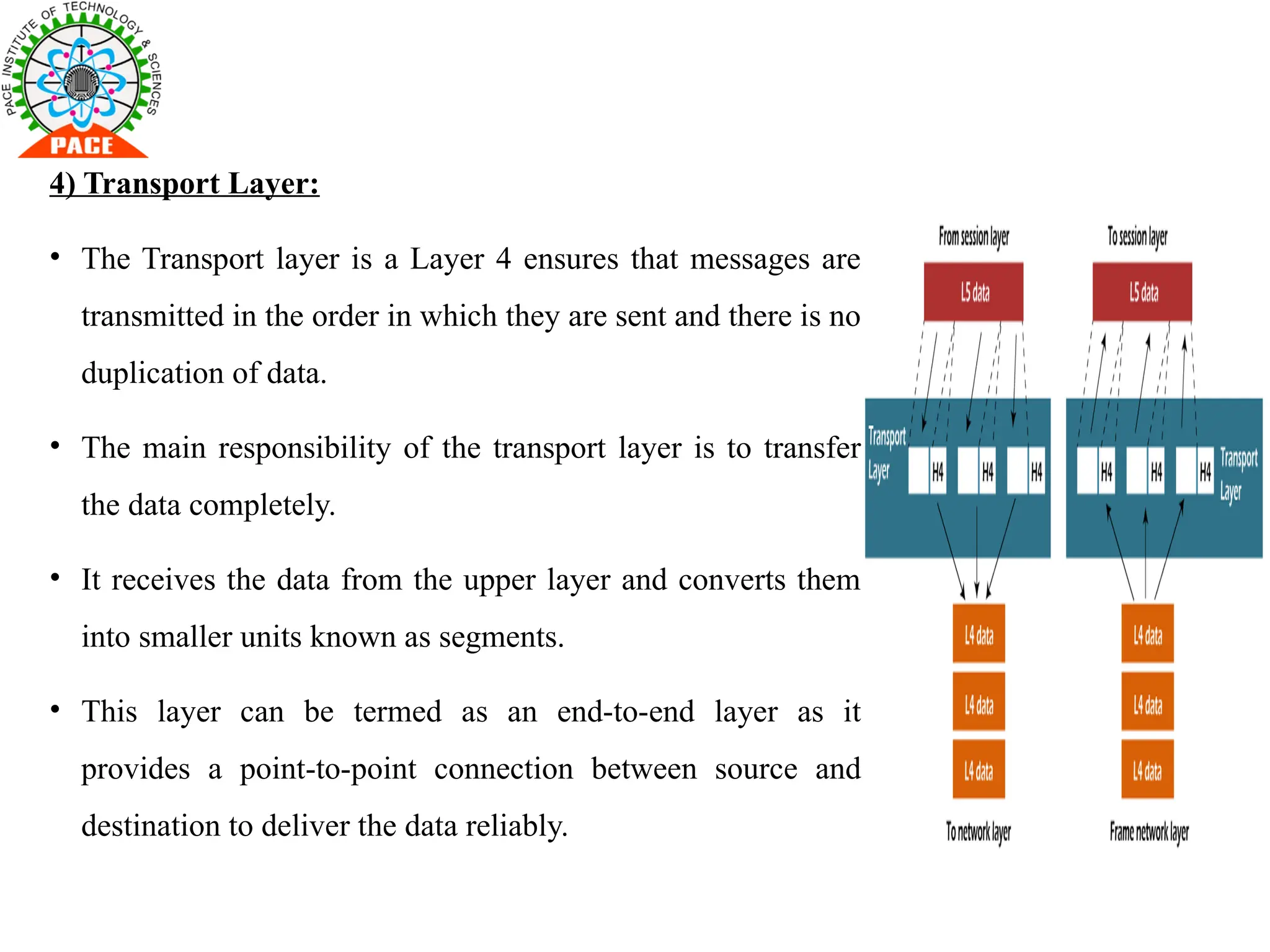
4) Transport Layer:
•The Transport layer is a Layer 4 ensures that messages are
transmitted in the order in which they are sent and there is no
duplication of data.
• The main responsibility of the transport layer is to transfer
the data completely.
• It receives the data from the upper layer and converts them
into smaller units known as segments.
• This layer can be termed as an end-to-end layer as it
provides a point-to-point connection between source and
destination to deliver the data reliably.
32.
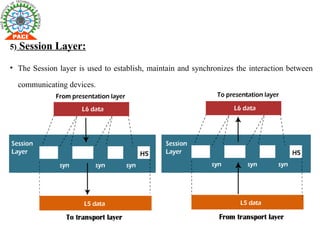
5) Session Layer:
•The Session layer is used to establish, maintain and synchronizes the interaction between
communicating devices.
33.
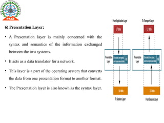
6) Presentation Layer:
•A Presentation layer is mainly concerned with the
syntax and semantics of the information exchanged
between the two systems.
• It acts as a data translator for a network.
• This layer is a part of the operating system that converts
the data from one presentation format to another format.
• The Presentation layer is also known as the syntax layer.
34.
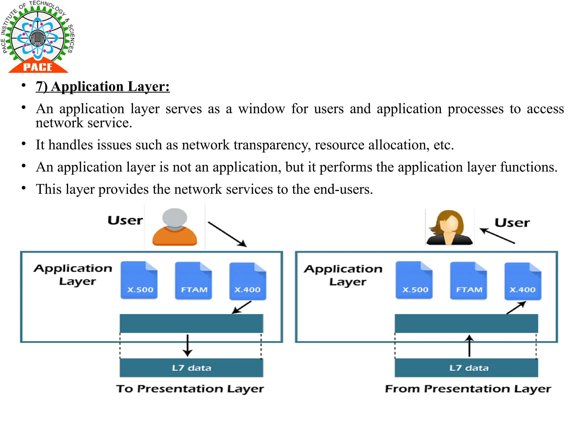
• 7) ApplicationLayer:
• An application layer serves as a window for users and application processes to access
network service.
• It handles issues such as network transparency, resource allocation, etc.
• An application layer is not an application, but it performs the application layer functions.
• This layer provides the network services to the end-users.
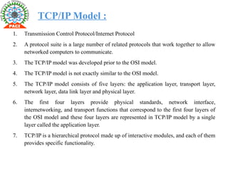
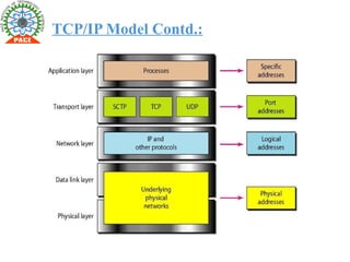
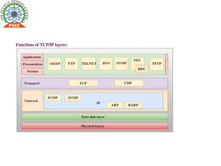
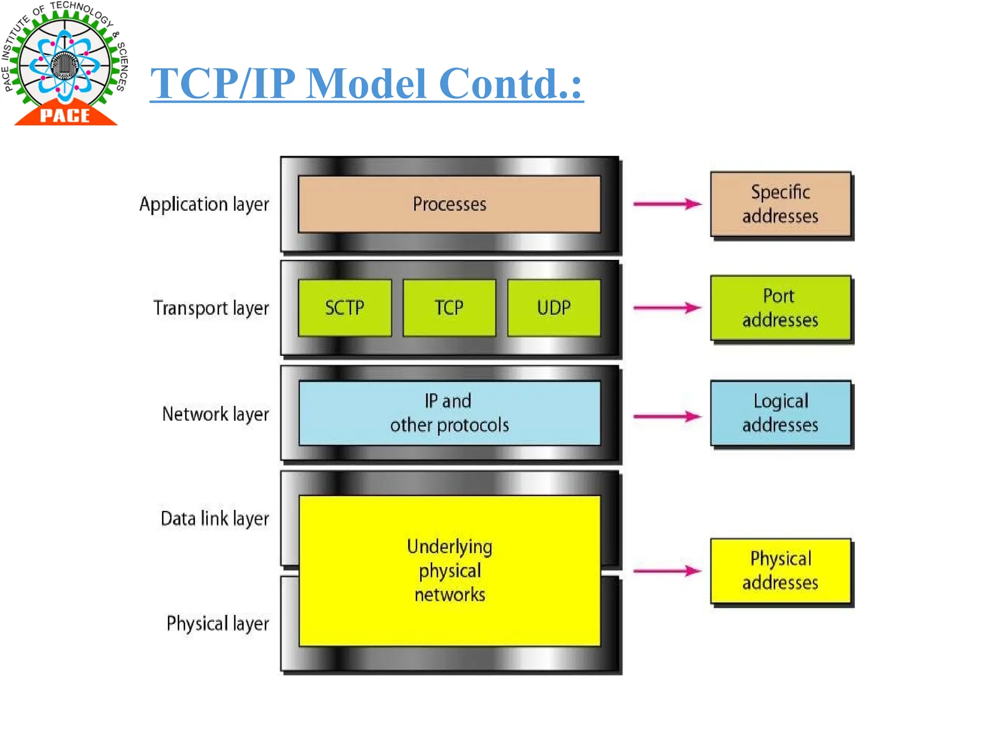
TCP/IP Model :
1.Transmission Control Protocol/Internet Protocol
2. A protocol suite is a large number of related protocols that work together to allow
networked computers to communicate.
3. The TCP/IP model was developed prior to the OSI model.
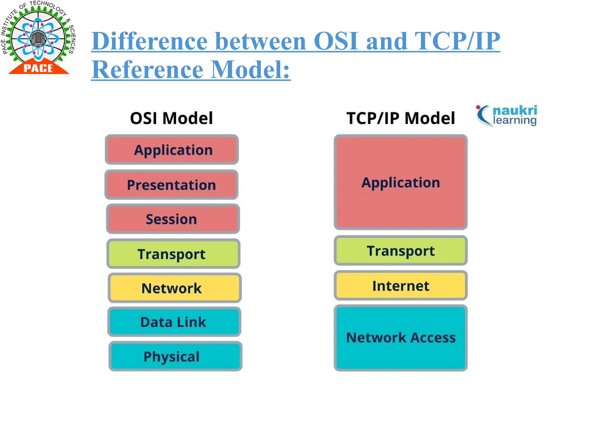
4. The TCP/IP model is not exactly similar to the OSI model.
5. The TCP/IP model consists of five layers: the application layer, transport layer,
network layer, data link layer and physical layer.
6. The first four layers provide physical standards, network interface,
internetworking, and transport functions that correspond to the first four layers of
the OSI model and these four layers are represented in TCP/IP model by a single
layer called the application layer.
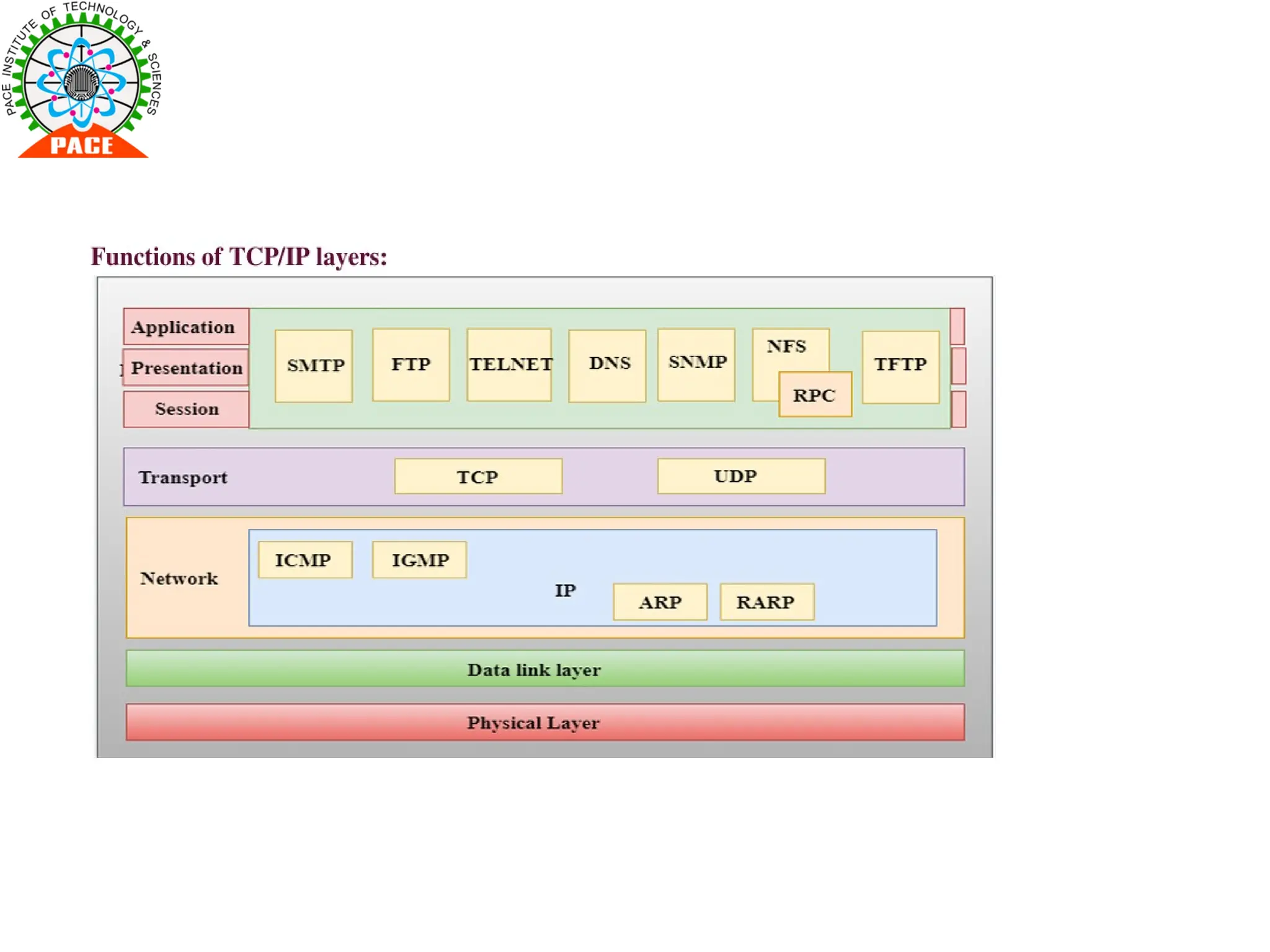
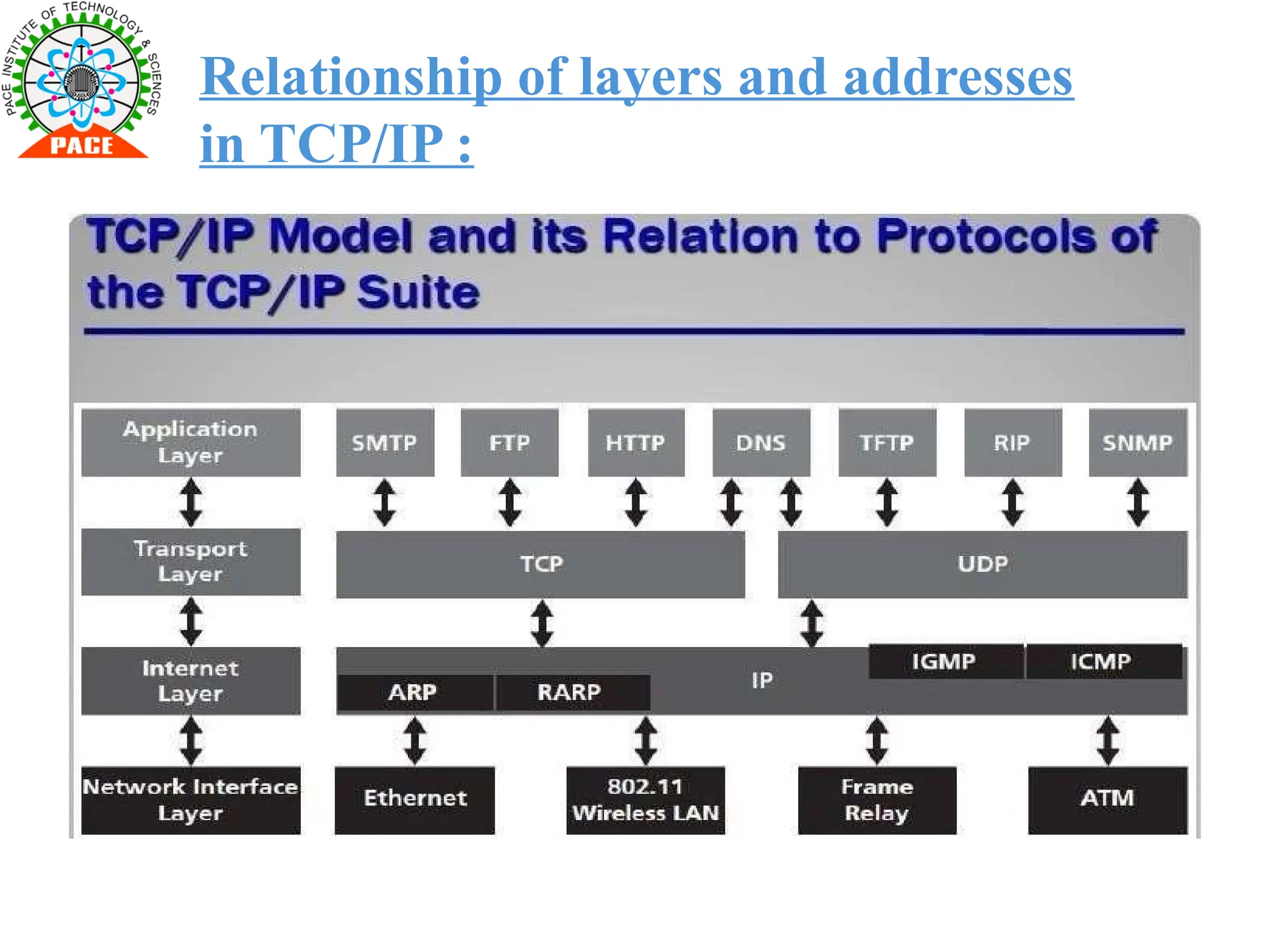
7. TCP/IP is a hierarchical protocol made up of interactive modules, and each of them
provides specific functionality.
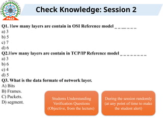
Check Knowledge: Session2
Q1. How many layers are contain in OSI Reference model _ _ __ _ _ _
a) 3
b) 5
c) 7
d) 6
Q2.How many layers are contain in TCP/IP Reference model _ _ _ _ _ _ _ _
a) 3
b) 6
c) 4
d) 5
Q3. What is the data formate of network layer.
A) Bits
B) Frames.
C) Packets.
D) segment.
Students Understanding
Verification Questions
(Objective, from the lecture)
During the session randomly
(at any point of time to make
the student alert)
43.
Homework
Draw the alldiagrams of OSI Reference model and TCP/IP Reference model
Homework
Questions/Programs/Problems