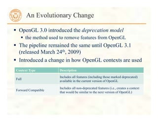
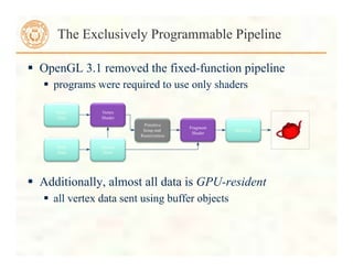
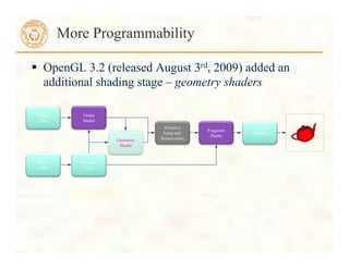
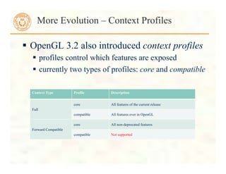
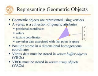
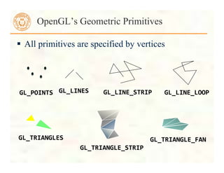
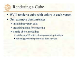
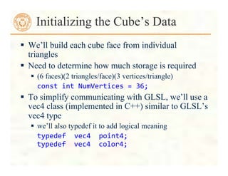
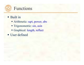
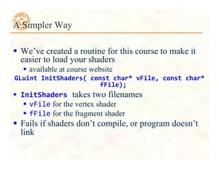
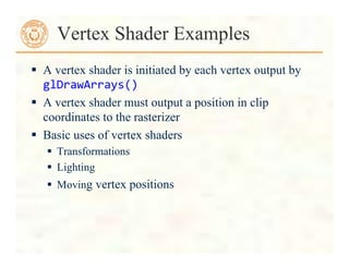
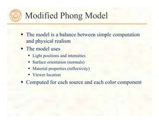
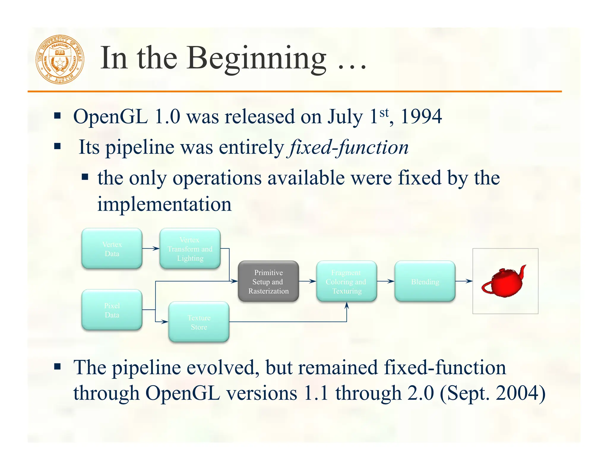
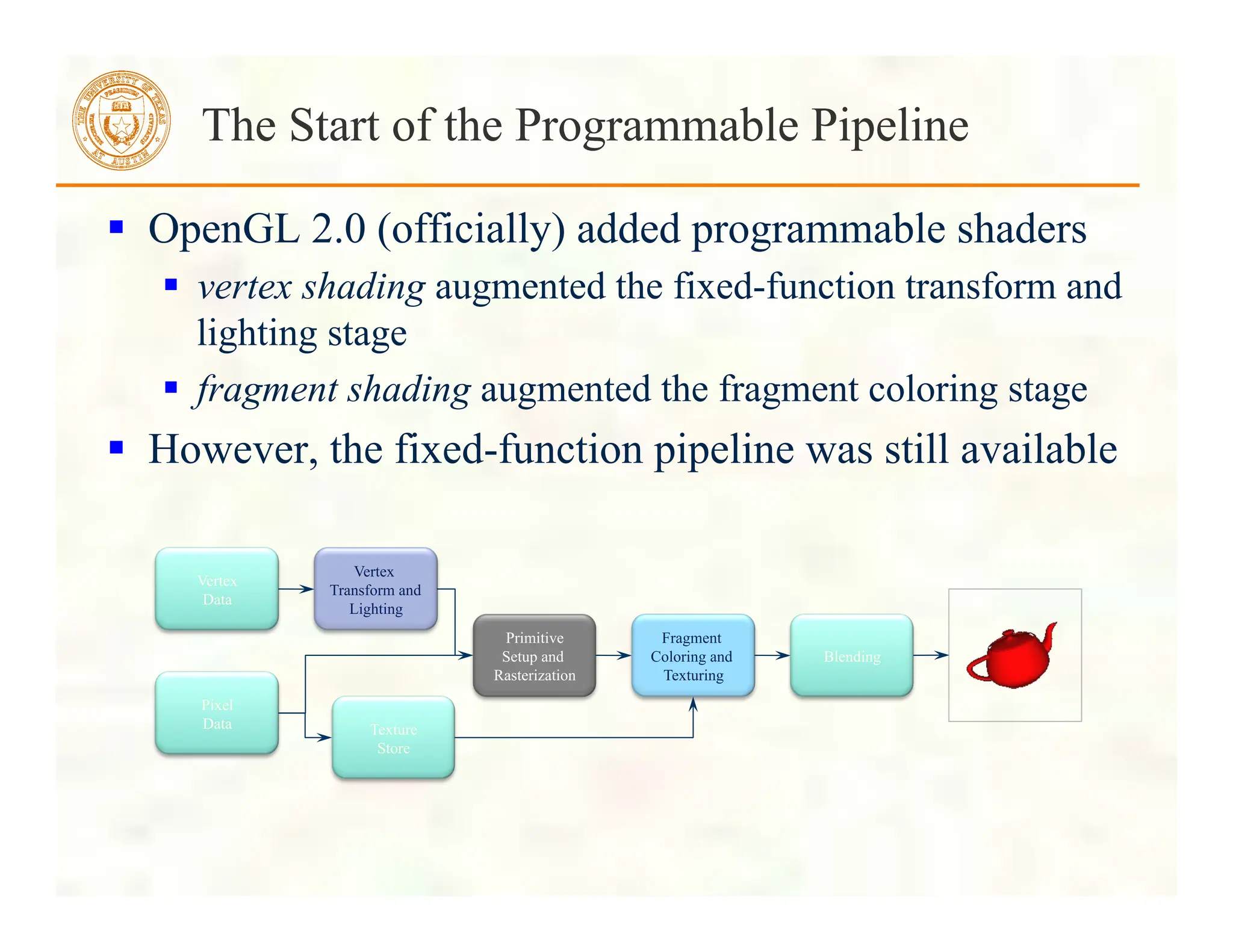
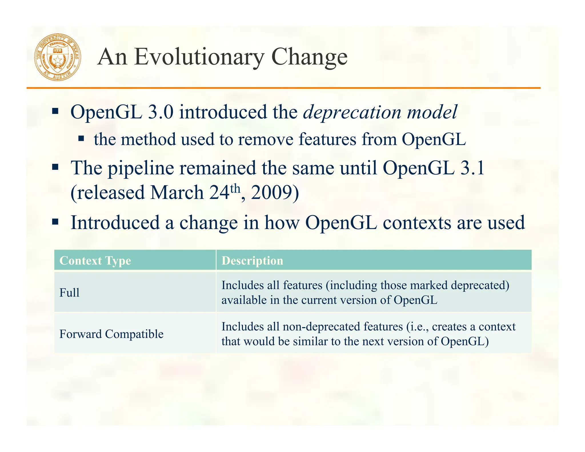
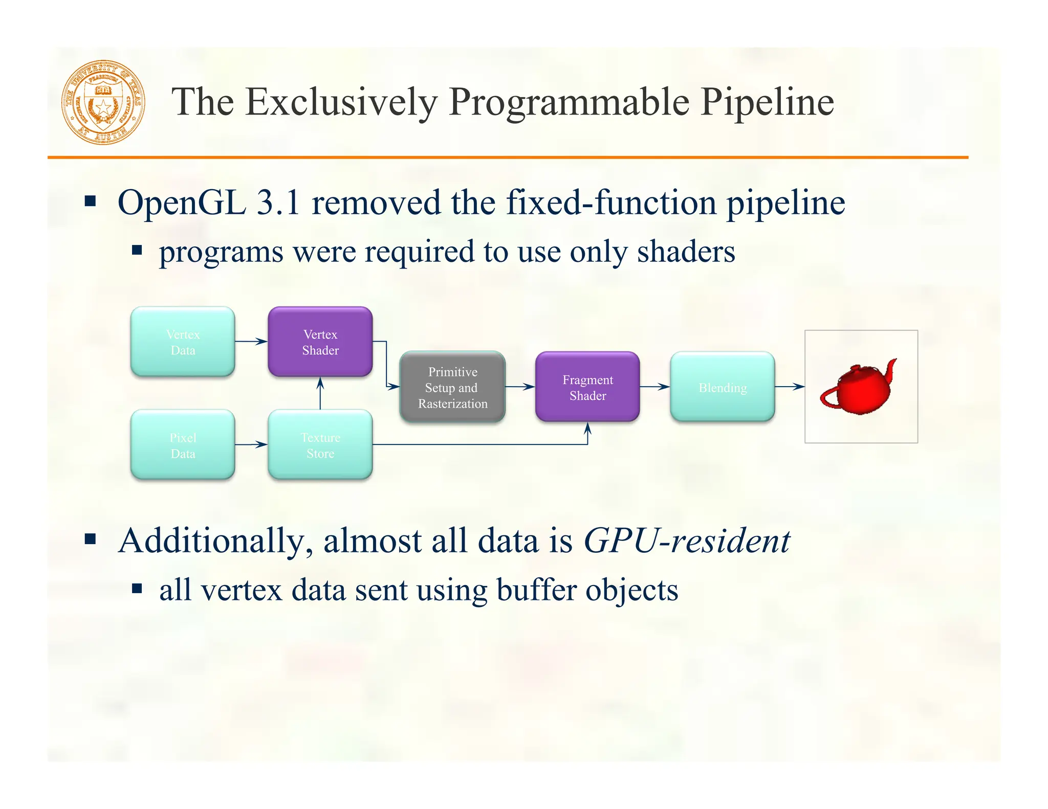
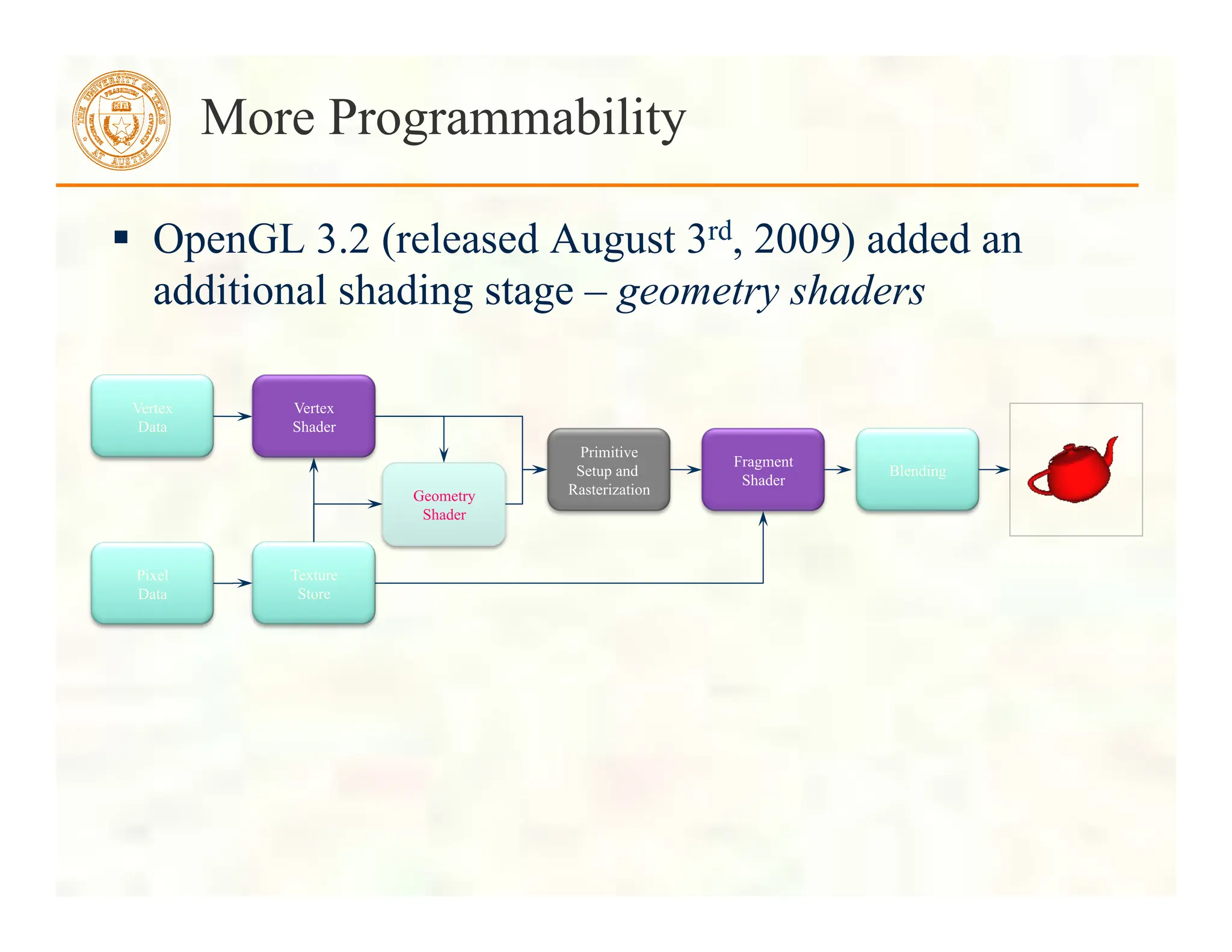
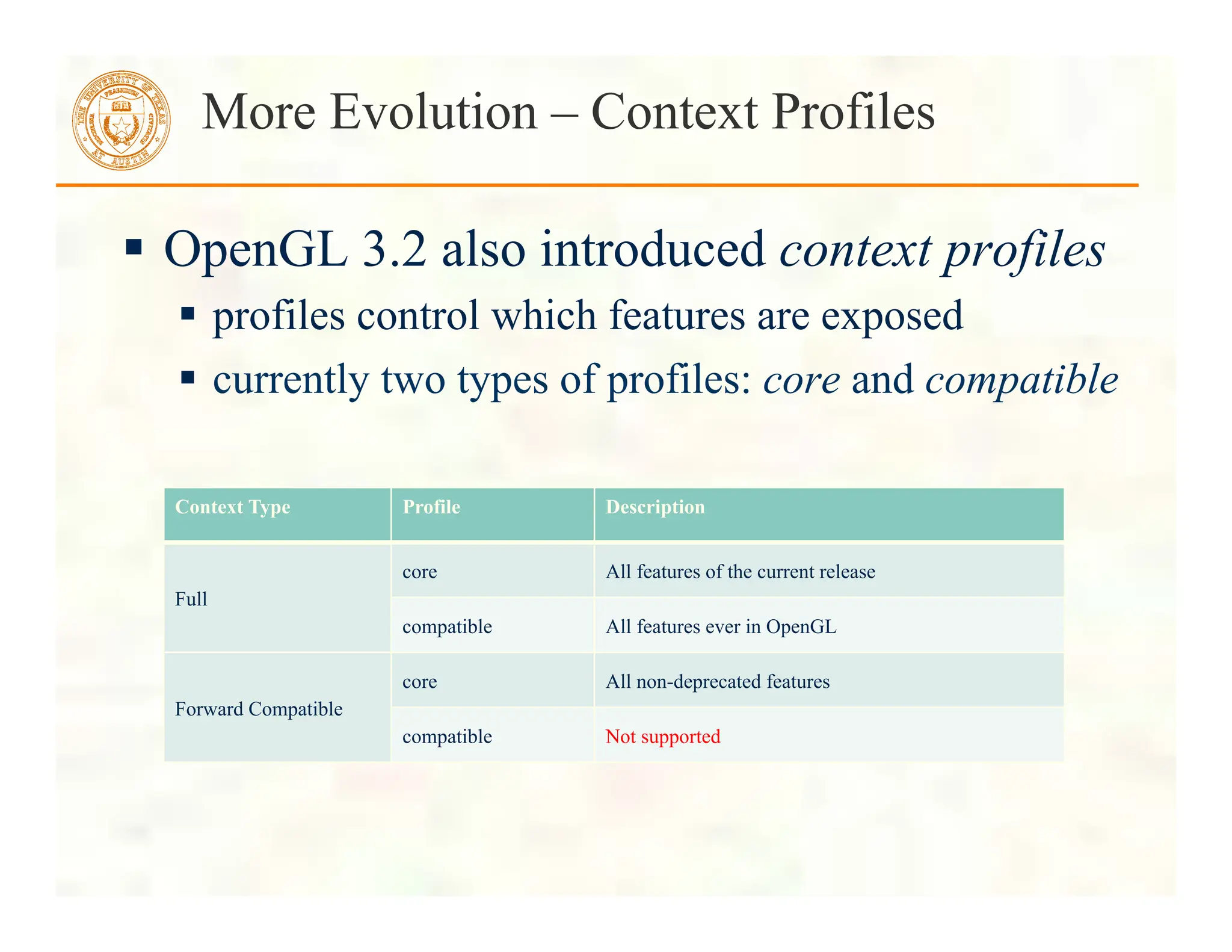
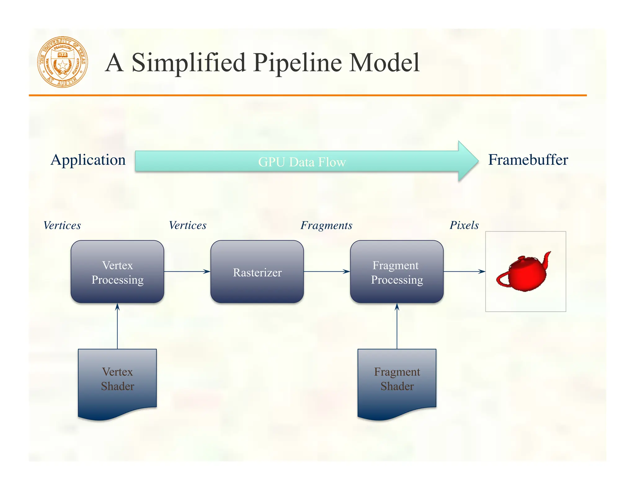
This document serves as an introduction to modern OpenGL programming, providing a history of the OpenGL pipeline and highlighting the transition from fixed-function to programmable shaders. It outlines the development of key features across various OpenGL versions, including the introduction of shaders and context profiles, as well as the necessary setup for application development using shader programs and vertex buffer objects. Additionally, it offers a foundational understanding of geometric representations and the basic steps for rendering 3D objects, such as a colored cube, using OpenGL.


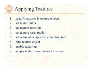
![ Before we can initialize our VBO, we need to stage the
data
Our cube has two attributes per vertex
position
color
We create two arrays to hold the VBO data
point4
points[NumVertices];
color4
colors[NumVertices];
Initializing the Cube’s Data (cont’d)](https://image.slidesharecdn.com/lecturexx-opengl-240502181618-904a2585/85/lectureAll-OpenGL-complete-Guide-Tutorial-pdf-24-320.jpg)
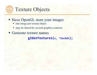
![//
Vertices
of
a
unit
cube
centered
at
origin,
sides
aligned
with
axes
point4
vertex_positions[8]
=
{
point4(
-‐0.5,
-‐0.5,
0.5,
1.0
),
point4(
-‐0.5,
0.5,
0.5,
1.0
),
point4(
0.5,
0.5,
0.5,
1.0
),
point4(
0.5,
-‐0.5,
0.5,
1.0
),
point4(
-‐0.5,
-‐0.5,
-‐0.5,
1.0
),
point4(
-‐0.5,
0.5,
-‐0.5,
1.0
),
point4(
0.5,
0.5,
-‐0.5,
1.0
),
point4(
0.5,
-‐0.5,
-‐0.5,
1.0
)
};
Cube Data](https://image.slidesharecdn.com/lecturexx-opengl-240502181618-904a2585/85/lectureAll-OpenGL-complete-Guide-Tutorial-pdf-25-320.jpg)
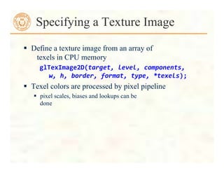
![//
RGBA
colors
color4
vertex_colors[8]
=
{
color4(
0.0,
0.0,
0.0,
1.0
),
//
black
color4(
1.0,
0.0,
0.0,
1.0
),
//
red
color4(
1.0,
1.0,
0.0,
1.0
),
//
yellow
color4(
0.0,
1.0,
0.0,
1.0
),
//
green
color4(
0.0,
0.0,
1.0,
1.0
),
//
blue
color4(
1.0,
0.0,
1.0,
1.0
),
//
magenta
color4(
1.0,
1.0,
1.0,
1.0
),
//
white
color4(
0.0,
1.0,
1.0,
1.0
)
//
cyan
};
Cube Data](https://image.slidesharecdn.com/lecturexx-opengl-240502181618-904a2585/85/lectureAll-OpenGL-complete-Guide-Tutorial-pdf-26-320.jpg)
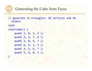
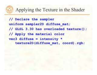
![// quad() generates two triangles for each face and assigns
colors to the vertices
int Index = 0; // global variable indexing into VBO arrays
void quad(int a, int b, int c, int d) {
colors[Index] = vertex_colors[a]; points[Index] =
vertex_positions[a]; Index++;
colors[Index] = vertex_colors[b]; points[Index] =
vertex_positions[b]; Index++;
colors[Index] = vertex_colors[c]; points[Index] =
vertex_positions[c]; Index++;
colors[Index] = vertex_colors[a]; points[Index] =
vertex_positions[a]; Index++;
colors[Index] = vertex_colors[c]; points[Index] =
vertex_positions[c]; Index++;
colors[Index] = vertex_colors[d]; points[Index] =
vertex_positions[d]; Index++;
}
Generating a Cube Face from Vertices](https://image.slidesharecdn.com/lecturexx-opengl-240502181618-904a2585/85/lectureAll-OpenGL-complete-Guide-Tutorial-pdf-27-320.jpg)

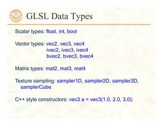
![For vectors can use [ ], xyzw, rgba or stpq
Example:
vec3
v;
v[1],
v.y,
v.g,
v.t
all refer to the same element
Swizzling:
vec3
a,
b;
a.xy
=
b.yx;
Components and Swizzling](https://image.slidesharecdn.com/lecturexx-opengl-240502181618-904a2585/85/lectureAll-OpenGL-complete-Guide-Tutorial-pdf-39-320.jpg)


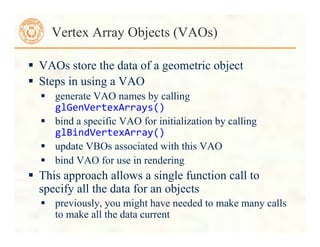
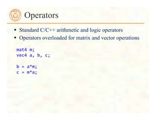
![Uniform Variables
glUniform4f(index,
x,
y,
z,
w);
Glboolean
transpose
=
GL_TRUE;
//
Since
we’re
C
programmers
Glfloat
mat[3][4][4]
=
{
…
};
glUniformMatrix4fv(index,
3,
transpose,
mat);
Initializing Uniform Variable Values](https://image.slidesharecdn.com/lecturexx-opengl-240502181618-904a2585/85/lectureAll-OpenGL-complete-Guide-Tutorial-pdf-50-320.jpg)


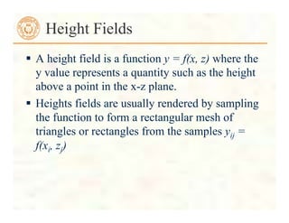
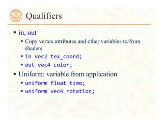
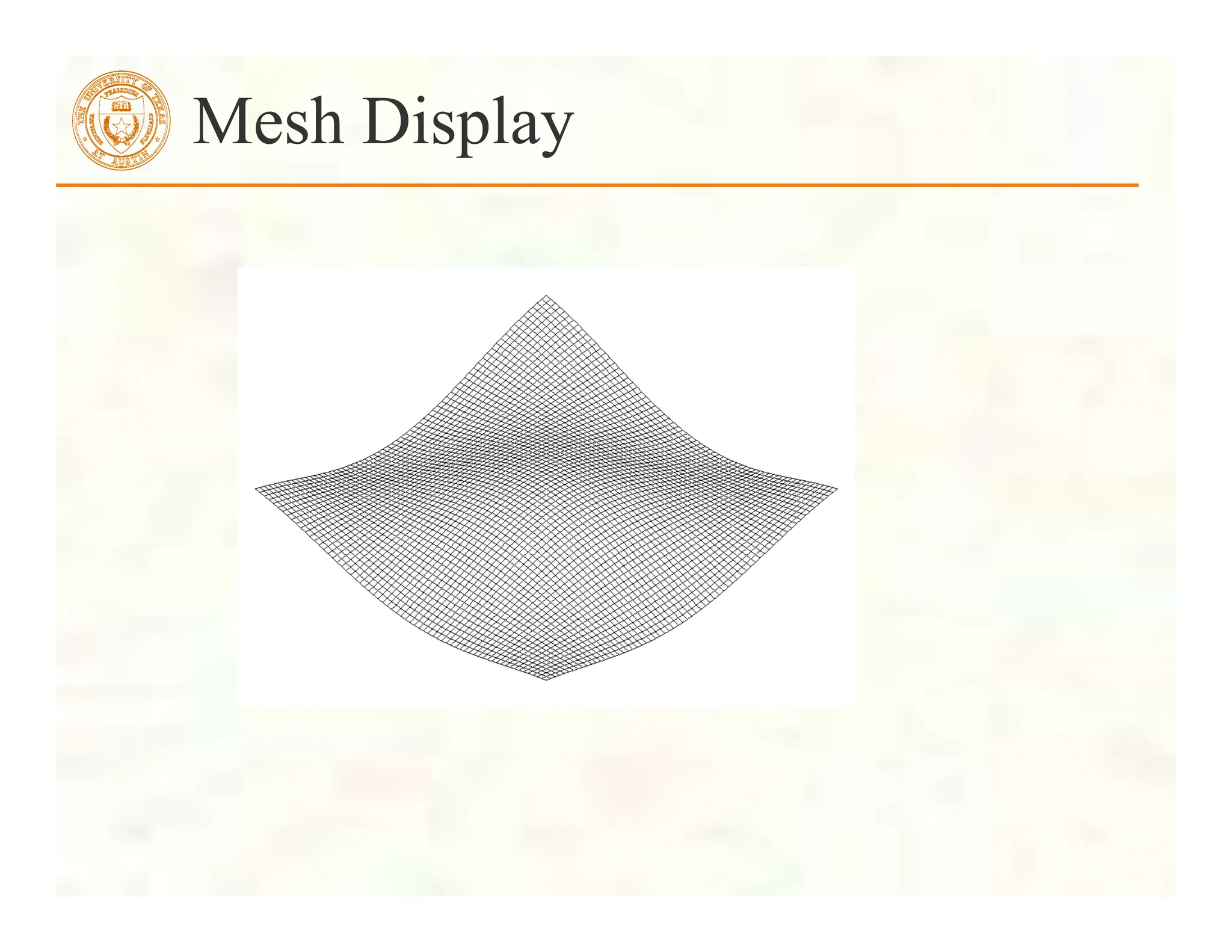
![ Form a quadrilateral mesh
Display each quad using
Displaying a Height Field
for(i=0;i<N;i++)
for(j=0;j<N;j++)
data[i][j]=f(i,
j,
time);
vertex[Index++]
=
vec3((float)i/N,
data[i][j],
(float)j/N);
vertex[Index++]
=
vec3((float)i/N,
data[i][j],
(float)(j+1)/N);
vertex[Index++]
=
vec3((float)(i+1)/N,
data[i][j],
(float)(j+1)/N);
vertex[Index++]
=
vec3((float)(i+1)/N,
data[i][j],
(float)(j)/N);
for(i=0;i<NumVertices
;i+=4)
glDrawArrays(GL_LINE_LOOP,
4*i,
4);](https://image.slidesharecdn.com/lecturexx-opengl-240502181618-904a2585/85/lectureAll-OpenGL-complete-Guide-Tutorial-pdf-84-320.jpg)


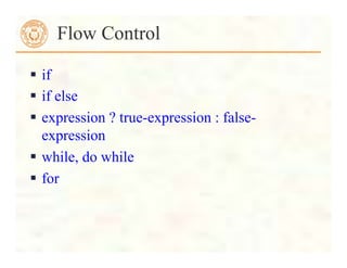
![Texturing the Cube
// add texture coordinate attribute to quad
function
quad(int a, int b, int c, int d) {
quad_colors[Index] = vertex_colors[a];
points[Index] = vertex_positions[a];
tex_coords[Index] = vec2(0.0, 0.0);
Index++;
… // rest of vertices
}](https://image.slidesharecdn.com/lecturexx-opengl-240502181618-904a2585/85/lectureAll-OpenGL-complete-Guide-Tutorial-pdf-101-320.jpg)
![Creating a Texture Image
// Create a checkerboard pattern
for (int i = 0; i < 64; i++) {
for (int j = 0; j < 64; j++) {
GLubyte c;
c = (((i & 0x8) == 0) ^ ((j & 0x8) == 0)) * 255;
image[i][j][0] = c;
image[i][j][1] = c;
image[i][j][2] = c;
image2[i][j][0] = c;
image2[i][j][1] = 0;
image2[i][j][2] = c;
}
}](https://image.slidesharecdn.com/lecturexx-opengl-240502181618-904a2585/85/lectureAll-OpenGL-complete-Guide-Tutorial-pdf-102-320.jpg)
![Texture Object
GLuint
textures[1];
glGenTextures(1,
textures);
glBindTexture(GL_TEXTURE_2D,
textures[0]);
glTexImage2D(GL_TEXTURE_2D,
0,
GL_RGB,
TextureSize,
TextureSize,
GL_RGB,
GL_UNSIGNED_BYTE,
image);
glTexParameterf(GL_TEXTURE_2D,
GL_TEXTURE_WRAP_S,
GL_REPEAT);
glTexParameterf(GL_TEXTURE_2D,
GL_TEXTURE_WRAP_T,
GL_REPEAT);
glTexParameterf(GL_TEXTURE_2D,
GL_TEXTURE_MAG_FILTER,
GL_NEAREST);
glTexParameterf(GL_TEXTURE_2D,
GL_TEXTURE_MIN_FILTER,
GL_NEAREST);
glActiveTexture(GL_TEXTURE0);](https://image.slidesharecdn.com/lecturexx-opengl-240502181618-904a2585/85/lectureAll-OpenGL-complete-Guide-Tutorial-pdf-103-320.jpg)
![University of Texas at Austin CS384G - Computer Graphics Fall 2010 Don Fussell 106
Next class: Visual Perception
" Topic:
How does the human visual system?
How do humans perceive color?
How do we represent color in computations?
" Read:
• Glassner, Principles of Digital Image Synthesis,
pp. 5-32. [Course reader pp.1-28]
• Watt , Chapter 15.
• Brian Wandell. Foundations of Vision. Sinauer
Associates, Sunderland, MA, pp. 45-50 and
69-97, 1995.
[Course reader pp. 29-34 and pp. 35-63]](https://image.slidesharecdn.com/lecturexx-opengl-240502181618-904a2585/85/lectureAll-OpenGL-complete-Guide-Tutorial-pdf-106-320.jpg)


![ Before we can initialize our VBO, we need to stage the
data
Our cube has two attributes per vertex
position
color
We create two arrays to hold the VBO data
point4
points[NumVertices];
color4
colors[NumVertices];
Initializing the Cube’s Data (cont’d)](https://image.slidesharecdn.com/lecturexx-opengl-240502181618-904a2585/75/lectureAll-OpenGL-complete-Guide-Tutorial-pdf-24-2048.jpg)
![//
Vertices
of
a
unit
cube
centered
at
origin,
sides
aligned
with
axes
point4
vertex_positions[8]
=
{
point4(
-‐0.5,
-‐0.5,
0.5,
1.0
),
point4(
-‐0.5,
0.5,
0.5,
1.0
),
point4(
0.5,
0.5,
0.5,
1.0
),
point4(
0.5,
-‐0.5,
0.5,
1.0
),
point4(
-‐0.5,
-‐0.5,
-‐0.5,
1.0
),
point4(
-‐0.5,
0.5,
-‐0.5,
1.0
),
point4(
0.5,
0.5,
-‐0.5,
1.0
),
point4(
0.5,
-‐0.5,
-‐0.5,
1.0
)
};
Cube Data](https://image.slidesharecdn.com/lecturexx-opengl-240502181618-904a2585/75/lectureAll-OpenGL-complete-Guide-Tutorial-pdf-25-2048.jpg)
![//
RGBA
colors
color4
vertex_colors[8]
=
{
color4(
0.0,
0.0,
0.0,
1.0
),
//
black
color4(
1.0,
0.0,
0.0,
1.0
),
//
red
color4(
1.0,
1.0,
0.0,
1.0
),
//
yellow
color4(
0.0,
1.0,
0.0,
1.0
),
//
green
color4(
0.0,
0.0,
1.0,
1.0
),
//
blue
color4(
1.0,
0.0,
1.0,
1.0
),
//
magenta
color4(
1.0,
1.0,
1.0,
1.0
),
//
white
color4(
0.0,
1.0,
1.0,
1.0
)
//
cyan
};
Cube Data](https://image.slidesharecdn.com/lecturexx-opengl-240502181618-904a2585/75/lectureAll-OpenGL-complete-Guide-Tutorial-pdf-26-2048.jpg)
![// quad() generates two triangles for each face and assigns
colors to the vertices
int Index = 0; // global variable indexing into VBO arrays
void quad(int a, int b, int c, int d) {
colors[Index] = vertex_colors[a]; points[Index] =
vertex_positions[a]; Index++;
colors[Index] = vertex_colors[b]; points[Index] =
vertex_positions[b]; Index++;
colors[Index] = vertex_colors[c]; points[Index] =
vertex_positions[c]; Index++;
colors[Index] = vertex_colors[a]; points[Index] =
vertex_positions[a]; Index++;
colors[Index] = vertex_colors[c]; points[Index] =
vertex_positions[c]; Index++;
colors[Index] = vertex_colors[d]; points[Index] =
vertex_positions[d]; Index++;
}
Generating a Cube Face from Vertices](https://image.slidesharecdn.com/lecturexx-opengl-240502181618-904a2585/75/lectureAll-OpenGL-complete-Guide-Tutorial-pdf-27-2048.jpg)


![For vectors can use [ ], xyzw, rgba or stpq
Example:
vec3
v;
v[1],
v.y,
v.g,
v.t
all refer to the same element
Swizzling:
vec3
a,
b;
a.xy
=
b.yx;
Components and Swizzling](https://image.slidesharecdn.com/lecturexx-opengl-240502181618-904a2585/75/lectureAll-OpenGL-complete-Guide-Tutorial-pdf-39-2048.jpg)

![Uniform Variables
glUniform4f(index,
x,
y,
z,
w);
Glboolean
transpose
=
GL_TRUE;
//
Since
we’re
C
programmers
Glfloat
mat[3][4][4]
=
{
…
};
glUniformMatrix4fv(index,
3,
transpose,
mat);
Initializing Uniform Variable Values](https://image.slidesharecdn.com/lecturexx-opengl-240502181618-904a2585/75/lectureAll-OpenGL-complete-Guide-Tutorial-pdf-50-2048.jpg)


![ Form a quadrilateral mesh
Display each quad using
Displaying a Height Field
for(i=0;i<N;i++)
for(j=0;j<N;j++)
data[i][j]=f(i,
j,
time);
vertex[Index++]
=
vec3((float)i/N,
data[i][j],
(float)j/N);
vertex[Index++]
=
vec3((float)i/N,
data[i][j],
(float)(j+1)/N);
vertex[Index++]
=
vec3((float)(i+1)/N,
data[i][j],
(float)(j+1)/N);
vertex[Index++]
=
vec3((float)(i+1)/N,
data[i][j],
(float)(j)/N);
for(i=0;i<NumVertices
;i+=4)
glDrawArrays(GL_LINE_LOOP,
4*i,
4);](https://image.slidesharecdn.com/lecturexx-opengl-240502181618-904a2585/75/lectureAll-OpenGL-complete-Guide-Tutorial-pdf-84-2048.jpg)

![Texturing the Cube
// add texture coordinate attribute to quad
function
quad(int a, int b, int c, int d) {
quad_colors[Index] = vertex_colors[a];
points[Index] = vertex_positions[a];
tex_coords[Index] = vec2(0.0, 0.0);
Index++;
… // rest of vertices
}](https://image.slidesharecdn.com/lecturexx-opengl-240502181618-904a2585/75/lectureAll-OpenGL-complete-Guide-Tutorial-pdf-101-2048.jpg)
![Creating a Texture Image
// Create a checkerboard pattern
for (int i = 0; i < 64; i++) {
for (int j = 0; j < 64; j++) {
GLubyte c;
c = (((i & 0x8) == 0) ^ ((j & 0x8) == 0)) * 255;
image[i][j][0] = c;
image[i][j][1] = c;
image[i][j][2] = c;
image2[i][j][0] = c;
image2[i][j][1] = 0;
image2[i][j][2] = c;
}
}](https://image.slidesharecdn.com/lecturexx-opengl-240502181618-904a2585/75/lectureAll-OpenGL-complete-Guide-Tutorial-pdf-102-2048.jpg)
![Texture Object
GLuint
textures[1];
glGenTextures(1,
textures);
glBindTexture(GL_TEXTURE_2D,
textures[0]);
glTexImage2D(GL_TEXTURE_2D,
0,
GL_RGB,
TextureSize,
TextureSize,
GL_RGB,
GL_UNSIGNED_BYTE,
image);
glTexParameterf(GL_TEXTURE_2D,
GL_TEXTURE_WRAP_S,
GL_REPEAT);
glTexParameterf(GL_TEXTURE_2D,
GL_TEXTURE_WRAP_T,
GL_REPEAT);
glTexParameterf(GL_TEXTURE_2D,
GL_TEXTURE_MAG_FILTER,
GL_NEAREST);
glTexParameterf(GL_TEXTURE_2D,
GL_TEXTURE_MIN_FILTER,
GL_NEAREST);
glActiveTexture(GL_TEXTURE0);](https://image.slidesharecdn.com/lecturexx-opengl-240502181618-904a2585/75/lectureAll-OpenGL-complete-Guide-Tutorial-pdf-103-2048.jpg)
![University of Texas at Austin CS384G - Computer Graphics Fall 2010 Don Fussell 106
Next class: Visual Perception
" Topic:
How does the human visual system?
How do humans perceive color?
How do we represent color in computations?
" Read:
• Glassner, Principles of Digital Image Synthesis,
pp. 5-32. [Course reader pp.1-28]
• Watt , Chapter 15.
• Brian Wandell. Foundations of Vision. Sinauer
Associates, Sunderland, MA, pp. 45-50 and
69-97, 1995.
[Course reader pp. 29-34 and pp. 35-63]](https://image.slidesharecdn.com/lecturexx-opengl-240502181618-904a2585/75/lectureAll-OpenGL-complete-Guide-Tutorial-pdf-106-2048.jpg)


