Downloaded 291 times
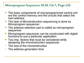
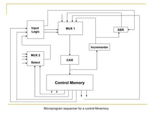
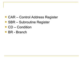

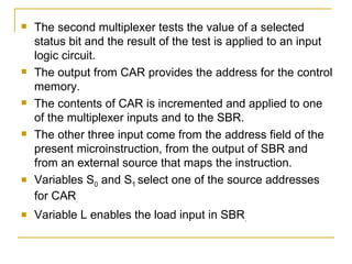


The document describes the components and functioning of a microprogram sequencer. The microprogram sequencer selects the next address from various sources like the current microinstruction address field, an incremented address, or an external source. It uses multiplexers and registers to select the appropriate next address and load it into the control address register to fetch the next microinstruction from memory. The input logic determines the types of operations the sequencer can perform, such as branching, subroutine calls and returns, and other address sequencing functions.


