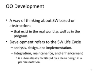
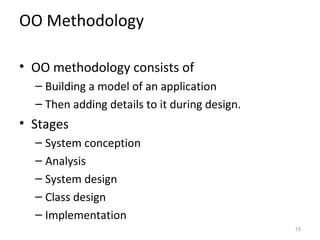
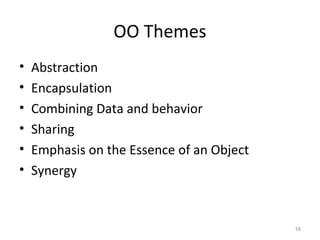
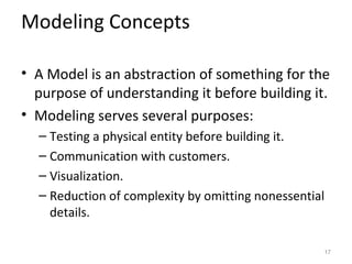
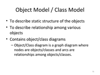
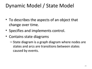
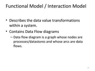
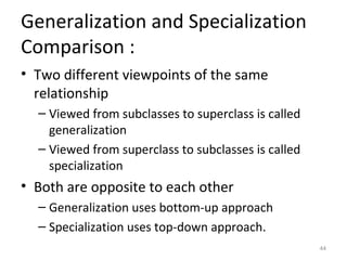
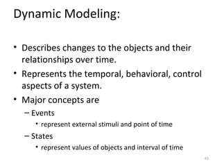
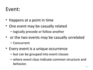
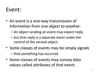
KEMBAR78
Object analysis and design | PPT
Object Oriented
Analysis & Design

    Amandeep S. Patti
   AP, Comp. Sc., PCTE
Object Oriented Analysis,
Modeling and Design
• OO is a SW development approach
• that is based on modeling objects from the
  real world
• and then using the model to build a Language-
  independent design.


                                              2
Object-oriented approach is used by:

•   OO Languages
•   OO Databases
•   OO Modeling
•   OO Methodology


                                       3
Object-oriented approach promotes:

•   Better Understanding of requirements,
•   Visualize a problem using graphical notations,
•   Cleaner designs,
•   And more maintainable systems.


                                                     4
Object oriented approach
is divided into:
• A set of object-oriented concepts
• A language-independent graphical notation
  which can be used to analyze problem
  requirements
• Design a solution to the problem,
• And then implement the solution in a
  programming language or in database


                                              5
Object-Orientation

• A way to organize software as a collection of
  discrete objects
  – that incorporate both data structure and
    behavior.
• This contrasts with previous programming
  approaches in which
  – data structure and behavior are only loosely
    connected.


                                                   6
Major aspects under
object-orientation:
•   Identity
•   Classification
•   Inheritance
•   Polymorphism


                      7
Identity

• Quantized data into
  – discrete, distinguishable entities called objects.
• Objects can be
  – concrete or conceptual
• Objects do have their own distinct identity
  – even if their attributes are same.
• Objects do have unique handle.
  – In comparison to real world where objects simply
    exists, in programming languages each object has a
    unique handle by which it is referenced.
                                                         8
Classification

• Objects with the same data structure
  (attributes) and behavior (operations) are
  grouped into a class.
• Class is an abstraction
  – that describes important properties to an
    application
  – and ignores the rest.
• Each object is an instance of its class.

                                                9
Inheritance

• Sharing or attributes and operations
  – among classes based on hierarchical relationship.
• A superclass is general information
  – that subclasses refine and elaborate.


                                                        10
Polymorphism

• Same operation may behave differently for
  different classes.
• An operation is a procedure or transformation
  – that an object performs or is subject to.
• An implementation of operation by a specific
  class
  – is called a method.


                                                 11
OO Development

• A way of thinking about SW based on
  abstractions
  – that exist in the real world as well as in the
    program.
• Development refers to the SW Life Cycle
  – analysis, design, and implementation.
  – Integration, maintenance, and enhancement
     • is automatically facilitated by a clean design in a
       precise notation.

                                                             12
OO Development

• Modeling concepts, not implementation
• OO Methodology
• Three Models


                                          13
Modeling concepts,
not implementation
• Front-end conceptual issues, rather than back-
  end implementation details.
• OO Modeling as a conceptual process
  – Independent of a programming language
• Serves as a medium
  – for specifications, analysis, documentation,
    interfacing and programming


                                                   14
OO Methodology

• OO methodology consists of
  – Building a model of an application
  – Then adding details to it during design.
• Stages
  – System conception
  – Analysis
  – System design
  – Class design
  – Implementation
                                               15
OO Themes
•   Abstraction
•   Encapsulation
•   Combining Data and behavior
•   Sharing
•   Emphasis on the Essence of an Object
•   Synergy


                                           16
Modeling Concepts

• A Model is an abstraction of something for the
  purpose of understanding it before building it.
• Modeling serves several purposes:
  – Testing a physical entity before building it.
  – Communication with customers.
  – Visualization.
  – Reduction of complexity by omitting nonessential
    details.

                                                   17
Object Modeling Technique – OMT

• Different models are used to describe a
  system from different viewpoints:
  – Object Model / Class Model
  – Dynamic Model / State Model
  – Functional Model / Interaction Model
• Three models are separate parts to describe
  system but are cross-linked.


                                                18
Object Model / Class Model
• To describe static structure of the objects
• To describe relationship among various
  objects
• Contains object/class diagrams
  – Object/Class diagram is a graph diagram where
    nodes are objects/classes and arcs are
    relationships among objects/classes.


                                                    19
Dynamic Model / State Model

• To describes the aspects of an object that
  change over time.
• Specifies and implements control.
• Contains state diagrams
  – State diagram is a graph diagram where nodes are
    states and arcs are transitions between states
    caused by events.


                                                   20
Functional Model / Interaction Model

• Describes the data value transformations
  within a system.
• Contains Data Flow diagrams
  – Data flow diagram is a graph whose nodes are
    processes/datastores and whose arcs are data
    flows.


                                                   21
Object Modeling:

• Describes a model which capture the static
  structure of a system
  – by specifying the objects in the system and
    relationship between them.
• Most important model
  – as it emphasize building a system around objects
    rather than around functionality.


                                                       22
Objects & Classes:
• Objects
  – Corresponds to real world entities
• Classes
  – Collection of the similar objects or entities.
• Each object is associated with the data of a
  class which they are created.


                                                     23
Object Diagrams:
• Provide a format for graphical notation for
  modeling the objects, classes and
  relationships to on another.
• Types of object diagrams:
  – Class Diagram
  – Instance Diagram


                                                24
Class Diagrams:

• Is a schema, pattern, or template for
  describing many possible instances of data.
• describe the general case in modeling a
  system.


                                                25
Instance Diagrams:

• Describes object instances and show how a
  particular set of objects relate to each other.
• Used mainly to show examples to help to
  clarify a complex class diagram.


                                                    26
Attributes:
• Data value held by the objects in class.
• Each attribute has a value for each object
  instance.
• Different object instances may have the same
  or different values for a given attribute.
• Each attribute name is unique within a class.
• Should describe values not objects.
• Attributes are listed in the second part of the
  class box.                                    27
Operations and Methods:

• An operation is a function or transformation
  – That may be applied to or by objects in class.
• All objects in a class share same operations.
• Same operation may apply to many different
  classes and is called polymorphic.
• A method is the implementation of an
  operation for a class.
• Operations listed in the lower part of the class
  box.                                               28
Links & Associations:

• A Link is a physical or conceptual connection
  between object instances.
• An association describes a group of links
  – with common structure and common semantics.
• Association and links often appear as verbs in
  the problem statements.
• An association describes a set of potential
  links in the same way that a class describes a
  set of potential objects.
                                                   29
Degree of association:

• Describes the number of classes connected by
  association:
  – Unary association or reflexive association
  – Binary association
  – Ternary association
  – Quaternary association
  – Higher order association


                                                 30
Multiplicity:
• Denotes the cardinality of the association.
• It shows how many instances of one class may
  relate to a single instance of an associated
  class.
  – One-to-one
  – One-to-many
  – Many-to-many


                                             31
Role Names:
• Uniquely identify one end of an association.
• Roles often appear as nouns in the problem
  statement.


                                                 32
Ordering:
• Objects on the “many” side of an association
  have no explicit order, and is regarded as a
  set.


                                                 33
Qualification:

• Special attribute that reduces the effective
  multiplicity of an association.
• A qualified association relates two object
  classes and a qualifier.


                                                 34
Aggregation:
• Is an extension of association
• Is the “part-whole” or “a-part-of” relationship
  – In which objects representing the components of
    something are associated with an object
    representing the entire assembly.


                                                      35
Generalization:
• Is the relationship between a class and one or
  more refined versions of it.
• Class being refined is called the superclass and
  each refined version is called a subclass.
• Is a bottom-up process.
• Attributes and operations common to a group
  of subclasses
  – are attached to the superclass
  – and shared by each subclass
                                                 36
Notation for Generalization:

• The notation for generalization is a triangle
  – Connecting a superclass to its subclasses.
  – The superclass is connected by a line to the apex
    or the triangle.
  – The subclasses are connected by lines to a
    horizontal bar attached to the base of the triangle
• The dangling subclass ellipsis is used to
  indicate that there are additional subclasses
  that are not shown.
                                                      37
Use of Generalization:

• Useful for conceptual modeling as well as for
  implementation
• Facilitates modeling
  – by structuring classes
  – capturing what is similar and what is different
    about classes.


                                                      38
Specialization:
• Is a mechanism for refining the definition or
  members of class.
• Is a top-down process.


                                                  39
Inheritance:
• Is a mechanism of sharing attributes and
  operations among classes.
• May be of type:
  – Single Inheritance
  – Multiple Inheritance


                                             40
Overriding Features:
• A Subclass may override a superclass feature
  by defining a feature with the same name.
• The overriding feature refines and replaces
  the overridden feature.


                                                 41
Association and Aggregation
Comparison :
• Both concepts provide the relationship among
  the classes.
• Aggregation is not an independent concept
  – but a special form of association.
  – exists after the existing of association.
• Associations are bidirectional but
  aggregations are antisymmetric.


                                                42
Aggregation and Generalization
Comparison :
• Aggregation provides the relationship
  between classes, while generalization is a
  process to combine the common behavior and
  attributers in a single or more classes.


                                           43
Generalization and Specialization
Comparison :
• Two different viewpoints of the same
  relationship
  – Viewed from subclasses to superclass is called
    generalization
  – Viewed from superclass to subclasses is called
    specialization
• Both are opposite to each other
  – Generalization uses bottom-up approach
  – Specialization uses top-down approach.
                                                     44
Dynamic Modeling:

• Describes changes to the objects and their
  relationships over time.
• Represents the temporal, behavioral, control
  aspects of a system.
• Major concepts are
  – Events
     • represent external stimuli and point of time
  – States
     • represent values of objects and interval of time
                                                          45
Event:
• Happens at a point in time
• One event may be casually related
  – logically precede or follow another
• or the two events may be casually unrelated
  – Concurrent
• Every event is a unique occurrence
  – but can be grouped into event classes
  – where event class indicate common structure and
    behavior.
                                                  46
Event:
• An event is a one-way transmission of
  information from one object to another.
  – An object sending an event may expect reply
  – but that reply is a separate event under the
    control of the second object.
• Some classes of events may be simply signals
  – that something has occurred
• Some classes of events may convey data
  values called attributes of that event.
                                                   47
Scenario:
• Is a sequence of events
  – that occurs during one particular execution of a
    system
• Scope of a scenario can vary
  – May include all events in the system
  – Or may include only those events impinging on or
    generated by certain objects in the system
• Next step after writing a scenario is to identify
  the sender and receiver objects of each event.
                                                       48
Event Trace Diagram:
• The sequence of events and the objects
  exchanging events can both be shown in an
  augmented scenario called an even trace
  diagram.
• Event diagrams shows
  – Each object as a vertical line
  – Each event as a horizontal arrow from the sender
    object to the receiver object

                                                       49
Event Trace Diagram:

• Time increases from top-to-bottom
• Only the sequences of events are shown
  – Not their exact timing.


                                           50
State:

• Is an abstraction of the attribute values and
  links of an objects.
• corresponds to the interval between two
  events received by an object.
• specifies the response of the object to input
  events.


                                                  51
State Diagram:

• Is used to relate events and states.
• On the occurrence of an event, next state
  depends
  – on the current state
  – as well as on the event
• A state diagram is a graph where
  – nodes are states and are drawn as rounded box
  – and directed arcs are transitions and are drawn as
    arrow and labeled by event names
                                                     52
Functional Modeling:

• Specifies the results of a computation without
  specifying how or when they are computed.
• Shows which values depend on which other
  values and the functions that relate them.


                                               53
Relation with Object
and Dynamic Models:
• The functional modal specifies
  – the meaning of the operations in the object model
  – and the actions in the dynamic model,
  – as well as any constraints in the object model.
• The Functional Model specifies what happens
• The Dynamic Model shows when it happens
• The Object Model specifies what it happens to

                                                    54
Data Flow Diagrams:

• Shows the functional relationships of the
  values computed by a system
  – Including input values, output values, and internal
    data stores
• DFD is a graph showing the flow of data values
  – from their sources
  – through processes that transforms them
  – to their destinations.

                                                      55
Data Flow Diagram Contains:

• Processes
  – that transform data
• Data Flows
  – that move data
• Actor objects
  – that produce or consume data
• Data store objects
  – that store data passively
                                   56
Processes:

• A process transforms data values.
• A process is drawn as an ellipse containing a
  description of the transformation.
• Each process has a fixed number of input and
  output data arrows.
• The lowest-level processes are pure functions.
• The high-level processes may be whole DFD.
• Processes are implemented as methods.
                                               57
Data Flows:

• A data flow connects the output of an object
  or process to the input of another object or
  process.
• A data flow is drawn as an arrow between the
  producer and the consumer of the data value.


                                             58
Data Flows:

• A fork with several arrows emerging from it
  may be used to represent
  – Flow of same value to several places
  – Splitting an aggregate data value into its
    components, each of which goes to a different
    place.


                                                    59
Actors:

• An actor is an active object that drives the
  data flow graph by producing or consuming
  values.
• Actors are attached to the inputs and outputs
  of a data flow graph.
• Also known as terminators.
• An actor is drawn as a rectangle.


                                                  60
Data stores:

• A data store is a passive object that stores
  data for later access.
• A data store allows values to be accessed in a
  different order than they are generated.
• It is drawn as a pair of parallel lines containing
  the name of the store.


                                                   61
Actors vs. Data stores:

• Both actors and data stores are objects.
• They are distinguished because of their
  behavior and usages.
• Data store might be implemented as a file and
  an actor as an external device.


                                              62
Context Diagram:

• It is the first DFD for every system.
• It shows the overall system processing as just
  one process and shows the data flows to and
  from external entities called actors.


                                                   63
Section A:

• Abstract Data Types: Model of Real World,
  Autonomy, Generation of correct
  Applications, Reusability Classes, Instance
  Values, Methods and Messages, Creating and
  destroying Objects, Constraints on object and
  Instance Variables, Pre and Post conditions of
  Methods.


                                                   64
Model of Real World:

• Real world objects are not like variables and
  functions
• They have attributes and behaviour.
• All the information is packaged under one
  name and can be reused as one specification
  or programming component.


                                                  65
Autonomy:

• Means independence, freedom from the hold
  of previous procedural programming
  approaches.
  – Redundant code is eliminated and the existing
    classes can be extended through inheritance.
  – Bugs in the program by usage of same member’s
    names can be avoided due to encapsulation.
  – Multiple instances may exist without interference.


                                                     66
Generation of Correct
Applications:
• OOAD simplifies the problem as it related the
  problem with real world.
• As abstraction in generated first that
  facilitates creating classes, thus chances of
  errors are avoided.
• Reusability of existing classes further helps in
  reducing errors


                                                     67
Reusability:


               68
Classes:


           69
Instance Values:

• By instance we mean an object and by
  instantiating a class, we make the objects of a
  class.
• Every instance got features from the class it is
  instantiated from but represent a completely
  different object.
• Values that represent an object identity and
  features form the instance values.

                                                 70
Methods and Messages:

• An object encapsulates data and algorithms
  called methods that process that data.
• Messages are the means by which the objects
  interact.
• A message stimulates some behaviour to
  occur in the receiving objet.


                                            71
Creating and Destroying Objects:

• Creation of objects is basically making copies
  of the class members.
• Memory allocation is done.
• Creation of objects also includes its
  initialization.
• Release the memory.


                                                   72
Constraints on Objects and
instance variables


                             73
Pre and Post Conditions or
Methods


                             74
Section A:

• Inheritance: Subsets as Subtypes, Sub typing of Structured
  Types Contrasting in inheritance with subtyping, Implicit
  Subtyping verses Explicit inheritance, Subtyping and dynamic
  binding class inheritance. Redefining Instance variables,
  Hiding Instance Variables inheriting methods, Method
  Overriding, Invoking Superclass method, Constrained
  Overriding, Inheriting the Interface, Excluding Super class
  Methods metaclasses, Explicit Support, Implicit of hidden
  Metaclasses, Object Oriented Languages without
  Metaclasses, Prototype Systems and Delegation, Multiple
  inheritance.


                                                             75
Inheritance:

• Deriving something more specific from a
  generalized existing thing.
• Common characteristics are collected into one
  specific class and other classes inherit that
  class.
• Core idea for reuse
• Avoid redundancy
• Leading to smaller models
                                              76
Inheritance with subtyping:

• Class is regarded as an implementation of a
  type
  – which defines certain behaviour.
• A subclass represents a subtype to a class.
• Ancestor represents a subset of the behaviour
  common to all the descendants.
• Subtyping normally occurs if the inheritance
  performs only an extension rather than
  overriding.
                                                77
Instance variables:

• A variable associated with a specific instance
  is called an instance variable.
• Instance variable store instance’s state.
• Encapsulation ensures that only one way to
  affect an object’s state, and that is though its
  operations.


                                                     78
Hiding instance variables:

• Local variable having the same name as
  instance variable can hide the instance
  variable.


                                            79
Overriding:

• Redefine some behaviour while inheriting
  from ancestor.
• With overriding, inheritance would not remain
  transitive.


                                              80
Invoking super class method:

• To use characteristics from more than one
  class.
• Controversial in the object-oriented
  community.
• Reduces understanding of a class hierarchy.
• Having same name in more than one super
  class creates problem


                                                81
System Design:

• It is the first design stage
   – in which the basic approach for solving the
     problem is selected.
• System architecture is the overall organization
  of the system into components called
  subsystems.


                                                   82
Key issues in System Design:

•   Organize the system into subsystems.
•   Identify concurrency inherent in the problem.
•   Allocate subsystems to processors and tasks.
•   Choose an approach for management of data stores.
•   Handle access to global resources.
•   Choose the implementation of control in software.
•   Handle Boundary Conditions.
•   Set trade-off Priorities.

                                                    83
Organize the system into
subsystems:
• A subsystem is usually identified by the service it
  provides.
• It is a package of
   – interrelated classes, associations, operations, events and
     constraints.
   – Are reasonably well-defined.
   – Interfaced with other subsystems.
• The lowest level subsystems are called modules.


                                                                  84
Organize the system into
subsystems:
• Relationship between two subsystems can be
  – Client-supplier relationship
  – Peer-to-peer relationship


                                               85
Organize the system into
subsystems:
• Client-supplier relationship
   – Client calls on the supplier, which perform some service
     and replies with a result.
   – Client must know the interface of the supplier, but the
     supplier does not have to know the interface


                                                                86
Organize the system into
subsystems:
• Peer-to-Peer relationship
   – Each of the subsystems may call on the others.
   – Subsystems must know each other's interface
      • Which makes it more complicated.
   – Peer-to-Peer Relationship
      • Each of the subsystems may call on the others.
      • Subsystems must know each other's interface.


                                                         87
Organize the system into
subsystems:
• Decomposition of system into subsystems:
  – Layered Architecture
     • Subsystem knows about the layers below it, but has no knowledge
       of the upper layers
     • Client supplier relationship exists between lower and upper layers
     • Each layer is implemented in terms of classes and operations of
       lower layers.
     • It may be Closed Architecture or Open Architecture
  – Partitions
     • Vertically divide a system into several independent or weakly
       coupled sybsystems.


                                                                       88
Identifying concurrency:

• The objects are said to be concurrent
   – if they can receive events at the same time
   – without interaction.
• Identify which objects must be active con-currently
  Identify which objects have activity that is mutually
  exclusive.


                                                          89
Allocate subsystems to
processors and tasks:
• Each concurrent subsystem must be allocated to a
  hardware unit
   – either a general purpose processor
   – or a specialized functional unit
• System designer must consider following aspects:
   – Estimate performance needs and the resources needed to
     satisfy them.
   – Choose h/w or s/w implementation for subsystem.


                                                          90
Choose an approach for
management of data stores:
• Data store may combine
  – Data structure
  – Databases
  – Data files


                             91
Handle access to
global resources.:
• System designer must Identify global resources and
  determine mechanism for controlling access to them
• Physical object
   – Can control itself by establishing a protocol for obtaining
     access within a concurrent system.
• Logical object (such as object ID)
   – There is danger of conflicting access in a shared
     environment.
• Global resource must be owned and locking
  mechanism should be implemented.
                                                                   92
Choose the implementation of
control in software:
• External Control
• Internal Control


                               93
Handle Boundary Conditions:

• Initialization
   – System must initial with all required things.
• Termination
   – System must contain the termination statements
   – Abnormal terminations must be avoided.
• Failure
   – Abnormal termination is called failure
   – May arise due to user errors, exhaustion of system
     resources, external breakdown.


                                                          94
Set trade-off Priorities:

• Based on relative importance of the various criteria


                                                         95
Common Architectural
Frameworks:
• Functional Transformation System
  – Batch Computation system
  – Continuous Transformation system
• Time dependent system
  – Interactive Interface
  – Dynamic simulation
• Database system
  – Transaction manager


                                       96

Object analysis and design

  • 1.
    Object Oriented Analysis &Design Amandeep S. Patti AP, Comp. Sc., PCTE
  • 2.
    Object Oriented Analysis, Modelingand Design • OO is a SW development approach • that is based on modeling objects from the real world • and then using the model to build a Language- independent design. 2
  • 3.
    Object-oriented approach isused by: • OO Languages • OO Databases • OO Modeling • OO Methodology 3
  • 4.
    Object-oriented approach promotes: • Better Understanding of requirements, • Visualize a problem using graphical notations, • Cleaner designs, • And more maintainable systems. 4
  • 5.
    Object oriented approach isdivided into: • A set of object-oriented concepts • A language-independent graphical notation which can be used to analyze problem requirements • Design a solution to the problem, • And then implement the solution in a programming language or in database 5
  • 6.
    Object-Orientation • A wayto organize software as a collection of discrete objects – that incorporate both data structure and behavior. • This contrasts with previous programming approaches in which – data structure and behavior are only loosely connected. 6
  • 7.
    Major aspects under object-orientation: • Identity • Classification • Inheritance • Polymorphism 7
  • 8.
    Identity • Quantized datainto – discrete, distinguishable entities called objects. • Objects can be – concrete or conceptual • Objects do have their own distinct identity – even if their attributes are same. • Objects do have unique handle. – In comparison to real world where objects simply exists, in programming languages each object has a unique handle by which it is referenced. 8
  • 9.
    Classification • Objects withthe same data structure (attributes) and behavior (operations) are grouped into a class. • Class is an abstraction – that describes important properties to an application – and ignores the rest. • Each object is an instance of its class. 9
  • 10.
    Inheritance • Sharing orattributes and operations – among classes based on hierarchical relationship. • A superclass is general information – that subclasses refine and elaborate. 10
  • 11.
    Polymorphism • Same operationmay behave differently for different classes. • An operation is a procedure or transformation – that an object performs or is subject to. • An implementation of operation by a specific class – is called a method. 11
  • 12.
    OO Development • Away of thinking about SW based on abstractions – that exist in the real world as well as in the program. • Development refers to the SW Life Cycle – analysis, design, and implementation. – Integration, maintenance, and enhancement • is automatically facilitated by a clean design in a precise notation. 12
  • 13.
    OO Development • Modelingconcepts, not implementation • OO Methodology • Three Models 13
  • 14.
    Modeling concepts, not implementation •Front-end conceptual issues, rather than back- end implementation details. • OO Modeling as a conceptual process – Independent of a programming language • Serves as a medium – for specifications, analysis, documentation, interfacing and programming 14
  • 15.
    OO Methodology • OOmethodology consists of – Building a model of an application – Then adding details to it during design. • Stages – System conception – Analysis – System design – Class design – Implementation 15
  • 16.
    OO Themes • Abstraction • Encapsulation • Combining Data and behavior • Sharing • Emphasis on the Essence of an Object • Synergy 16
  • 17.
    Modeling Concepts • AModel is an abstraction of something for the purpose of understanding it before building it. • Modeling serves several purposes: – Testing a physical entity before building it. – Communication with customers. – Visualization. – Reduction of complexity by omitting nonessential details. 17
  • 18.
    Object Modeling Technique– OMT • Different models are used to describe a system from different viewpoints: – Object Model / Class Model – Dynamic Model / State Model – Functional Model / Interaction Model • Three models are separate parts to describe system but are cross-linked. 18
  • 19.
    Object Model /Class Model • To describe static structure of the objects • To describe relationship among various objects • Contains object/class diagrams – Object/Class diagram is a graph diagram where nodes are objects/classes and arcs are relationships among objects/classes. 19
  • 20.
    Dynamic Model /State Model • To describes the aspects of an object that change over time. • Specifies and implements control. • Contains state diagrams – State diagram is a graph diagram where nodes are states and arcs are transitions between states caused by events. 20
  • 21.
    Functional Model /Interaction Model • Describes the data value transformations within a system. • Contains Data Flow diagrams – Data flow diagram is a graph whose nodes are processes/datastores and whose arcs are data flows. 21
  • 22.
    Object Modeling: • Describesa model which capture the static structure of a system – by specifying the objects in the system and relationship between them. • Most important model – as it emphasize building a system around objects rather than around functionality. 22
  • 23.
    Objects & Classes: •Objects – Corresponds to real world entities • Classes – Collection of the similar objects or entities. • Each object is associated with the data of a class which they are created. 23
  • 24.
    Object Diagrams: • Providea format for graphical notation for modeling the objects, classes and relationships to on another. • Types of object diagrams: – Class Diagram – Instance Diagram 24
  • 25.
    Class Diagrams: • Isa schema, pattern, or template for describing many possible instances of data. • describe the general case in modeling a system. 25
  • 26.
    Instance Diagrams: • Describesobject instances and show how a particular set of objects relate to each other. • Used mainly to show examples to help to clarify a complex class diagram. 26
  • 27.
    Attributes: • Data valueheld by the objects in class. • Each attribute has a value for each object instance. • Different object instances may have the same or different values for a given attribute. • Each attribute name is unique within a class. • Should describe values not objects. • Attributes are listed in the second part of the class box. 27
  • 28.
    Operations and Methods: •An operation is a function or transformation – That may be applied to or by objects in class. • All objects in a class share same operations. • Same operation may apply to many different classes and is called polymorphic. • A method is the implementation of an operation for a class. • Operations listed in the lower part of the class box. 28
  • 29.
    Links & Associations: •A Link is a physical or conceptual connection between object instances. • An association describes a group of links – with common structure and common semantics. • Association and links often appear as verbs in the problem statements. • An association describes a set of potential links in the same way that a class describes a set of potential objects. 29
  • 30.
    Degree of association: •Describes the number of classes connected by association: – Unary association or reflexive association – Binary association – Ternary association – Quaternary association – Higher order association 30
  • 31.
    Multiplicity: • Denotes thecardinality of the association. • It shows how many instances of one class may relate to a single instance of an associated class. – One-to-one – One-to-many – Many-to-many 31
  • 32.
    Role Names: • Uniquelyidentify one end of an association. • Roles often appear as nouns in the problem statement. 32
  • 33.
    Ordering: • Objects onthe “many” side of an association have no explicit order, and is regarded as a set. 33
  • 34.
    Qualification: • Special attributethat reduces the effective multiplicity of an association. • A qualified association relates two object classes and a qualifier. 34
  • 35.
    Aggregation: • Is anextension of association • Is the “part-whole” or “a-part-of” relationship – In which objects representing the components of something are associated with an object representing the entire assembly. 35
  • 36.
    Generalization: • Is therelationship between a class and one or more refined versions of it. • Class being refined is called the superclass and each refined version is called a subclass. • Is a bottom-up process. • Attributes and operations common to a group of subclasses – are attached to the superclass – and shared by each subclass 36
  • 37.
    Notation for Generalization: •The notation for generalization is a triangle – Connecting a superclass to its subclasses. – The superclass is connected by a line to the apex or the triangle. – The subclasses are connected by lines to a horizontal bar attached to the base of the triangle • The dangling subclass ellipsis is used to indicate that there are additional subclasses that are not shown. 37
  • 38.
    Use of Generalization: •Useful for conceptual modeling as well as for implementation • Facilitates modeling – by structuring classes – capturing what is similar and what is different about classes. 38
  • 39.
    Specialization: • Is amechanism for refining the definition or members of class. • Is a top-down process. 39
  • 40.
    Inheritance: • Is amechanism of sharing attributes and operations among classes. • May be of type: – Single Inheritance – Multiple Inheritance 40
  • 41.
    Overriding Features: • ASubclass may override a superclass feature by defining a feature with the same name. • The overriding feature refines and replaces the overridden feature. 41
  • 42.
    Association and Aggregation Comparison: • Both concepts provide the relationship among the classes. • Aggregation is not an independent concept – but a special form of association. – exists after the existing of association. • Associations are bidirectional but aggregations are antisymmetric. 42
  • 43.
    Aggregation and Generalization Comparison: • Aggregation provides the relationship between classes, while generalization is a process to combine the common behavior and attributers in a single or more classes. 43
  • 44.
    Generalization and Specialization Comparison: • Two different viewpoints of the same relationship – Viewed from subclasses to superclass is called generalization – Viewed from superclass to subclasses is called specialization • Both are opposite to each other – Generalization uses bottom-up approach – Specialization uses top-down approach. 44
  • 45.
    Dynamic Modeling: • Describeschanges to the objects and their relationships over time. • Represents the temporal, behavioral, control aspects of a system. • Major concepts are – Events • represent external stimuli and point of time – States • represent values of objects and interval of time 45
  • 46.
    Event: • Happens ata point in time • One event may be casually related – logically precede or follow another • or the two events may be casually unrelated – Concurrent • Every event is a unique occurrence – but can be grouped into event classes – where event class indicate common structure and behavior. 46
  • 47.
    Event: • An eventis a one-way transmission of information from one object to another. – An object sending an event may expect reply – but that reply is a separate event under the control of the second object. • Some classes of events may be simply signals – that something has occurred • Some classes of events may convey data values called attributes of that event. 47
  • 48.
    Scenario: • Is asequence of events – that occurs during one particular execution of a system • Scope of a scenario can vary – May include all events in the system – Or may include only those events impinging on or generated by certain objects in the system • Next step after writing a scenario is to identify the sender and receiver objects of each event. 48
  • 49.
    Event Trace Diagram: •The sequence of events and the objects exchanging events can both be shown in an augmented scenario called an even trace diagram. • Event diagrams shows – Each object as a vertical line – Each event as a horizontal arrow from the sender object to the receiver object 49
  • 50.
    Event Trace Diagram: •Time increases from top-to-bottom • Only the sequences of events are shown – Not their exact timing. 50
  • 51.
    State: • Is anabstraction of the attribute values and links of an objects. • corresponds to the interval between two events received by an object. • specifies the response of the object to input events. 51
  • 52.
    State Diagram: • Isused to relate events and states. • On the occurrence of an event, next state depends – on the current state – as well as on the event • A state diagram is a graph where – nodes are states and are drawn as rounded box – and directed arcs are transitions and are drawn as arrow and labeled by event names 52
  • 53.
    Functional Modeling: • Specifiesthe results of a computation without specifying how or when they are computed. • Shows which values depend on which other values and the functions that relate them. 53
  • 54.
    Relation with Object andDynamic Models: • The functional modal specifies – the meaning of the operations in the object model – and the actions in the dynamic model, – as well as any constraints in the object model. • The Functional Model specifies what happens • The Dynamic Model shows when it happens • The Object Model specifies what it happens to 54
  • 55.
    Data Flow Diagrams: •Shows the functional relationships of the values computed by a system – Including input values, output values, and internal data stores • DFD is a graph showing the flow of data values – from their sources – through processes that transforms them – to their destinations. 55
  • 56.
    Data Flow DiagramContains: • Processes – that transform data • Data Flows – that move data • Actor objects – that produce or consume data • Data store objects – that store data passively 56
  • 57.
    Processes: • A processtransforms data values. • A process is drawn as an ellipse containing a description of the transformation. • Each process has a fixed number of input and output data arrows. • The lowest-level processes are pure functions. • The high-level processes may be whole DFD. • Processes are implemented as methods. 57
  • 58.
    Data Flows: • Adata flow connects the output of an object or process to the input of another object or process. • A data flow is drawn as an arrow between the producer and the consumer of the data value. 58
  • 59.
    Data Flows: • Afork with several arrows emerging from it may be used to represent – Flow of same value to several places – Splitting an aggregate data value into its components, each of which goes to a different place. 59
  • 60.
    Actors: • An actoris an active object that drives the data flow graph by producing or consuming values. • Actors are attached to the inputs and outputs of a data flow graph. • Also known as terminators. • An actor is drawn as a rectangle. 60
  • 61.
    Data stores: • Adata store is a passive object that stores data for later access. • A data store allows values to be accessed in a different order than they are generated. • It is drawn as a pair of parallel lines containing the name of the store. 61
  • 62.
    Actors vs. Datastores: • Both actors and data stores are objects. • They are distinguished because of their behavior and usages. • Data store might be implemented as a file and an actor as an external device. 62
  • 63.
    Context Diagram: • Itis the first DFD for every system. • It shows the overall system processing as just one process and shows the data flows to and from external entities called actors. 63
  • 64.
    Section A: • AbstractData Types: Model of Real World, Autonomy, Generation of correct Applications, Reusability Classes, Instance Values, Methods and Messages, Creating and destroying Objects, Constraints on object and Instance Variables, Pre and Post conditions of Methods. 64
  • 65.
    Model of RealWorld: • Real world objects are not like variables and functions • They have attributes and behaviour. • All the information is packaged under one name and can be reused as one specification or programming component. 65
  • 66.
    Autonomy: • Means independence,freedom from the hold of previous procedural programming approaches. – Redundant code is eliminated and the existing classes can be extended through inheritance. – Bugs in the program by usage of same member’s names can be avoided due to encapsulation. – Multiple instances may exist without interference. 66
  • 67.
    Generation of Correct Applications: •OOAD simplifies the problem as it related the problem with real world. • As abstraction in generated first that facilitates creating classes, thus chances of errors are avoided. • Reusability of existing classes further helps in reducing errors 67
  • 68.
  • 69.
  • 70.
    Instance Values: • Byinstance we mean an object and by instantiating a class, we make the objects of a class. • Every instance got features from the class it is instantiated from but represent a completely different object. • Values that represent an object identity and features form the instance values. 70
  • 71.
    Methods and Messages: •An object encapsulates data and algorithms called methods that process that data. • Messages are the means by which the objects interact. • A message stimulates some behaviour to occur in the receiving objet. 71
  • 72.
    Creating and DestroyingObjects: • Creation of objects is basically making copies of the class members. • Memory allocation is done. • Creation of objects also includes its initialization. • Release the memory. 72
  • 73.
    Constraints on Objectsand instance variables 73
  • 74.
    Pre and PostConditions or Methods 74
  • 75.
    Section A: • Inheritance:Subsets as Subtypes, Sub typing of Structured Types Contrasting in inheritance with subtyping, Implicit Subtyping verses Explicit inheritance, Subtyping and dynamic binding class inheritance. Redefining Instance variables, Hiding Instance Variables inheriting methods, Method Overriding, Invoking Superclass method, Constrained Overriding, Inheriting the Interface, Excluding Super class Methods metaclasses, Explicit Support, Implicit of hidden Metaclasses, Object Oriented Languages without Metaclasses, Prototype Systems and Delegation, Multiple inheritance. 75
  • 76.
    Inheritance: • Deriving somethingmore specific from a generalized existing thing. • Common characteristics are collected into one specific class and other classes inherit that class. • Core idea for reuse • Avoid redundancy • Leading to smaller models 76
  • 77.
    Inheritance with subtyping: •Class is regarded as an implementation of a type – which defines certain behaviour. • A subclass represents a subtype to a class. • Ancestor represents a subset of the behaviour common to all the descendants. • Subtyping normally occurs if the inheritance performs only an extension rather than overriding. 77
  • 78.
    Instance variables: • Avariable associated with a specific instance is called an instance variable. • Instance variable store instance’s state. • Encapsulation ensures that only one way to affect an object’s state, and that is though its operations. 78
  • 79.
    Hiding instance variables: •Local variable having the same name as instance variable can hide the instance variable. 79
  • 80.
    Overriding: • Redefine somebehaviour while inheriting from ancestor. • With overriding, inheritance would not remain transitive. 80
  • 81.
    Invoking super classmethod: • To use characteristics from more than one class. • Controversial in the object-oriented community. • Reduces understanding of a class hierarchy. • Having same name in more than one super class creates problem 81
  • 82.
    System Design: • Itis the first design stage – in which the basic approach for solving the problem is selected. • System architecture is the overall organization of the system into components called subsystems. 82
  • 83.
    Key issues inSystem Design: • Organize the system into subsystems. • Identify concurrency inherent in the problem. • Allocate subsystems to processors and tasks. • Choose an approach for management of data stores. • Handle access to global resources. • Choose the implementation of control in software. • Handle Boundary Conditions. • Set trade-off Priorities. 83
  • 84.
    Organize the systeminto subsystems: • A subsystem is usually identified by the service it provides. • It is a package of – interrelated classes, associations, operations, events and constraints. – Are reasonably well-defined. – Interfaced with other subsystems. • The lowest level subsystems are called modules. 84
  • 85.
    Organize the systeminto subsystems: • Relationship between two subsystems can be – Client-supplier relationship – Peer-to-peer relationship 85
  • 86.
    Organize the systeminto subsystems: • Client-supplier relationship – Client calls on the supplier, which perform some service and replies with a result. – Client must know the interface of the supplier, but the supplier does not have to know the interface 86
  • 87.
    Organize the systeminto subsystems: • Peer-to-Peer relationship – Each of the subsystems may call on the others. – Subsystems must know each other's interface • Which makes it more complicated. – Peer-to-Peer Relationship • Each of the subsystems may call on the others. • Subsystems must know each other's interface. 87
  • 88.
    Organize the systeminto subsystems: • Decomposition of system into subsystems: – Layered Architecture • Subsystem knows about the layers below it, but has no knowledge of the upper layers • Client supplier relationship exists between lower and upper layers • Each layer is implemented in terms of classes and operations of lower layers. • It may be Closed Architecture or Open Architecture – Partitions • Vertically divide a system into several independent or weakly coupled sybsystems. 88
  • 89.
    Identifying concurrency: • Theobjects are said to be concurrent – if they can receive events at the same time – without interaction. • Identify which objects must be active con-currently Identify which objects have activity that is mutually exclusive. 89
  • 90.
    Allocate subsystems to processorsand tasks: • Each concurrent subsystem must be allocated to a hardware unit – either a general purpose processor – or a specialized functional unit • System designer must consider following aspects: – Estimate performance needs and the resources needed to satisfy them. – Choose h/w or s/w implementation for subsystem. 90
  • 91.
    Choose an approachfor management of data stores: • Data store may combine – Data structure – Databases – Data files 91
  • 92.
    Handle access to globalresources.: • System designer must Identify global resources and determine mechanism for controlling access to them • Physical object – Can control itself by establishing a protocol for obtaining access within a concurrent system. • Logical object (such as object ID) – There is danger of conflicting access in a shared environment. • Global resource must be owned and locking mechanism should be implemented. 92
  • 93.
    Choose the implementationof control in software: • External Control • Internal Control 93
  • 94.
    Handle Boundary Conditions: •Initialization – System must initial with all required things. • Termination – System must contain the termination statements – Abnormal terminations must be avoided. • Failure – Abnormal termination is called failure – May arise due to user errors, exhaustion of system resources, external breakdown. 94
  • 95.
    Set trade-off Priorities: •Based on relative importance of the various criteria 95
  • 96.
    Common Architectural Frameworks: • FunctionalTransformation System – Batch Computation system – Continuous Transformation system • Time dependent system – Interactive Interface – Dynamic simulation • Database system – Transaction manager 96