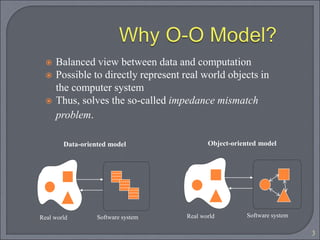
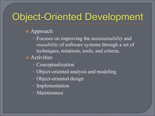
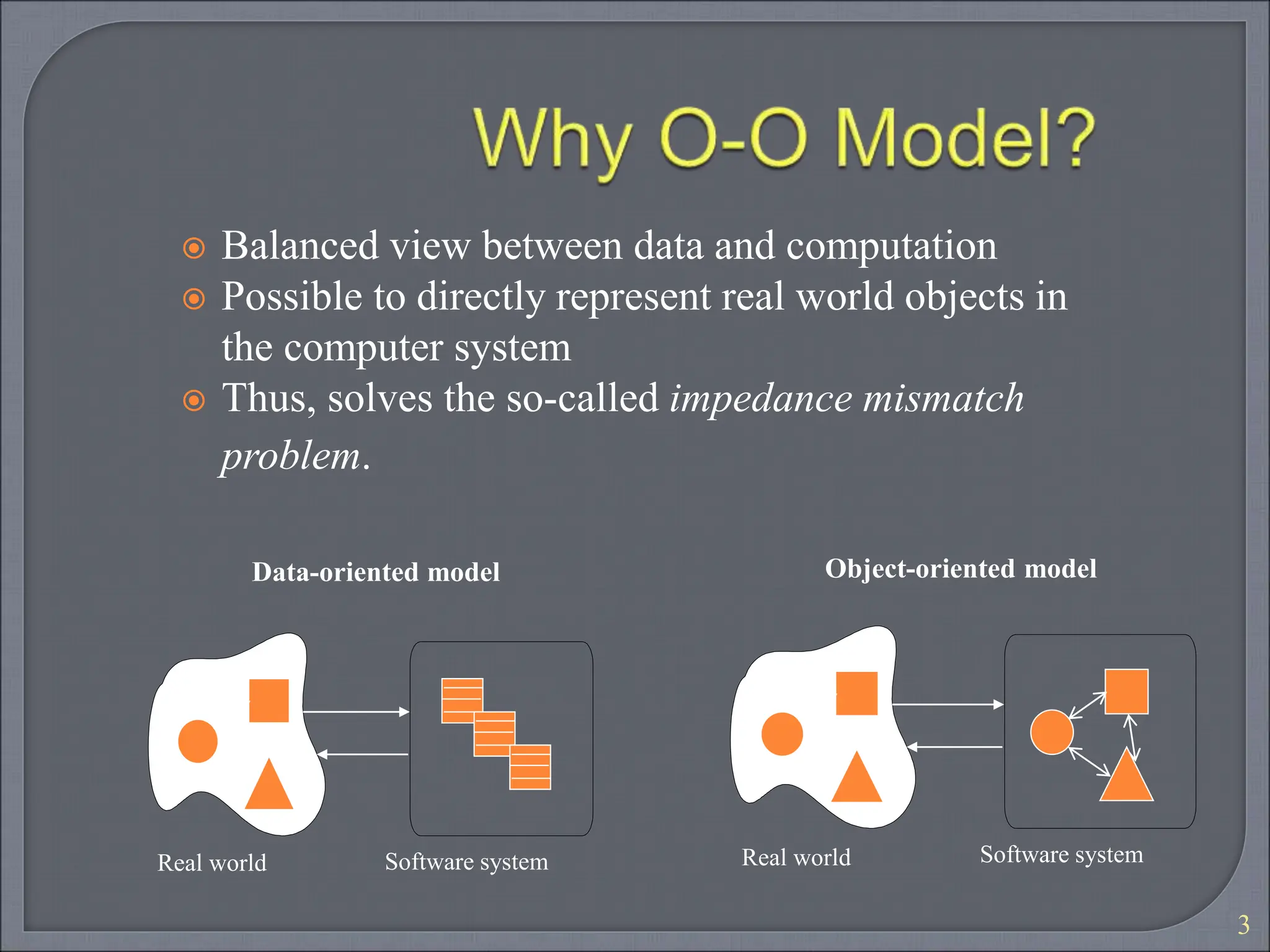
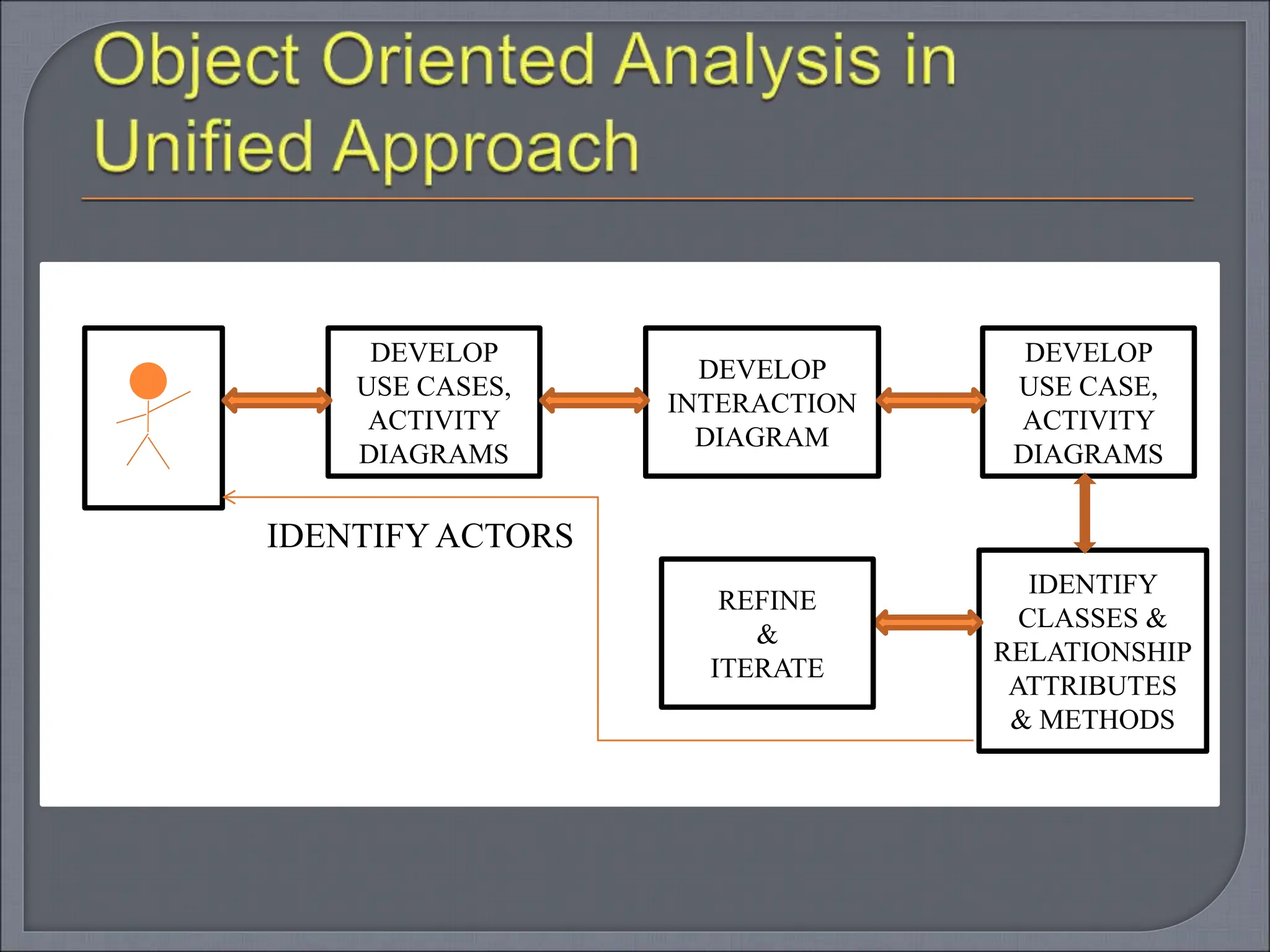
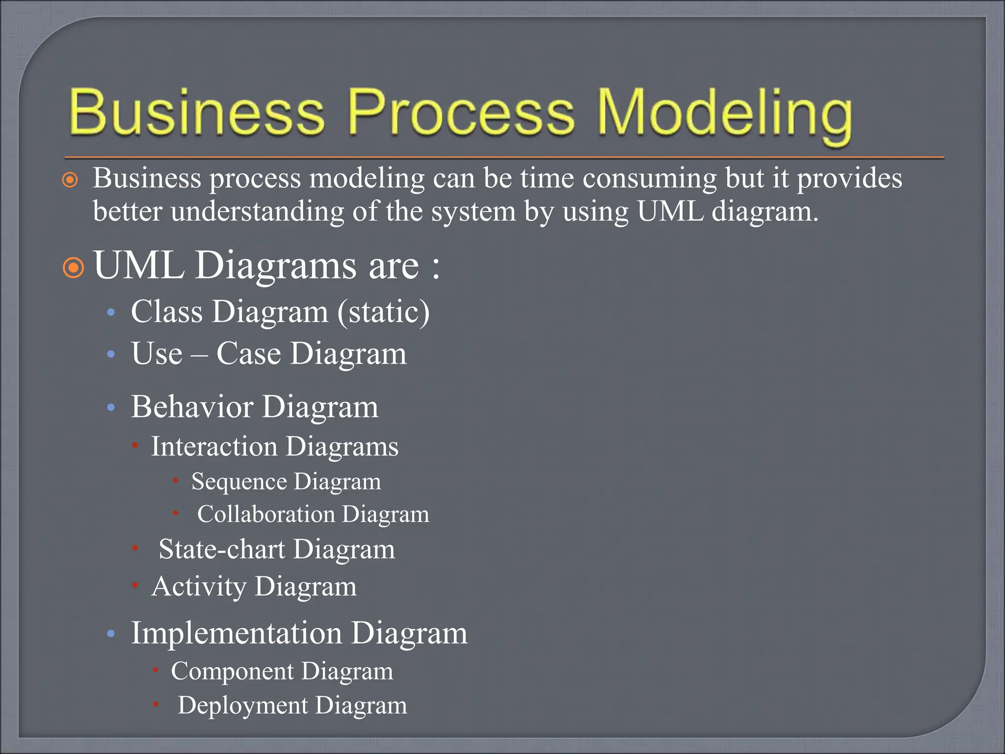
KEMBAR78
OBJECT ORIENTED ANALYSIS FOR EASY UNDERSTANDING .ppt
Complexity of software systems
Longevity and evolution of software
systems
High user expectations
2
3
 Balanced view between data and computation
 Possible to directly represent real world objects in
the computer system
 Thus, solves the so-called impedance mismatch
problem.
Software system
Real world
Data-oriented model
Software system
Real world
Object-oriented model
 Approach
• Focuses on improving the maintainability and
reusability of software systems through a set of
techniques, notations, tools, and criteria.
 Activities
• Conceptualization
• Object-oriented analysis and modeling
• Object-oriented design
• Implementation
• Maintenance
Analysis
Design
Implementation and unit testing
Integration and system testing
Maintenance
Goals
• To define the problem to be solved, i.e., to establish
the functions, services, and constraints of the
software to be developed.
Deliverables
• Requirements specifications itemizing the
functional and nonfunctional requirements, called
system specifications.
To find an appropriate solution to a given
problem.
To understand the problem and problem
domain.
Objective of Analysis
To capture a Complete, unambiguous and
consistent picture of the requirements.
What the system must do to satisfy the user ?
Hence the ANALYSIS is the process of
transforming a problem definition from a fuzzy
set of facts and myth into a coherent statement
of system’s requirements.
Analysis includes USER – INTERACTION.
 Analysis is an iterative process that goes on until the problem
is well understood. Usually difficulties in analysis are
1. Fuzzy Descriptions : Fast response time which leads user
dissatisfaction.
2. Incomplete Requirements : Few requirements which are
important but not included
at the time of analysis.
3. Unnecessary features : Unwanted modules which may effect the
performance may increase complexity,
reduces stability & maintenance of the
system.
Deadlines : Time given to deliver a software.
Comparative evaluation – Comparison of new
Software with existing one, may ask a
developer to include extra feature.
 It is a process of understanding the system requirements
and establishing the goal of an application.
 Main intent is to understand User’s need.
 Outcome of this phase is
1. To identify Classes and their relationships in
achieving system goal.
2. To understand expected inputs to get desired
outputs or response from system.
 Another tool to understand user’s need is preparing a
prototype of user interface
IDENTIFYACTORS
DEVELOP
USE CASES,
ACTIVITY
DIAGRAMS
DEVELOP
INTERACTION
DIAGRAM
DEVELOP
USE CASE,
ACTIVITY
DIAGRAMS
IDENTIFY
CLASSES &
RELATIONSHIP
ATTRIBUTES
& METHODS
REFINE
&
ITERATE
Unified Approach
• This approach uses Use Cases to describe the system
from user’s perspective.
• Use Cases are scenarios that describes how actors use
this system
Steps involved in Object Oriented Analysis
• Identifying Actors(Users).
• Develop a simple business process model using UML
activity diagrams.
• Develop use case – which provides comprehensive
documentation of the system under study.
• Prepare interaction diagrams –sequence, collaboration
• Classification – Identify Classes, Relations, Attributes,
methods
 Business process modeling can be time consuming but it provides
better understanding of the system by using UML diagram.
 UML Diagrams are :
• Class Diagram (static)
• Use – Case Diagram
• Behavior Diagram
 Interaction Diagrams
 Sequence Diagram
 Collaboration Diagram
 State-chart Diagram
 Activity Diagram
• Implementation Diagram
 Component Diagram
 Deployment Diagram
A USE – CASE is a sequence of transactions in
a system whose task is to submit result of
measurable value to an individual actor of the
system.
It shows interaction between users and system
Captures the goal and responsibility of system
to its user.
It also describe the events that can be
performed.
 Identifies classes and relationships among the
subsystem(different modules) of the system.
 A Use-Case must have a name with little
description.
 Hence it provides an external view of a system or
application.
 Explain
• What this application will do and not.
• How the events will take place and can be handled
• UML Class Diagram which also known as OBJECT
MODEL represents internal view of an system.
 It uses the words like - Uses & extends Association
• Sometime we must use a use case without defining
it again and again which occurs more than one time
in a system for example in a library process
Checking Library card may occur while borrowing
book, returning book, for getting interlibrary loan
etc hence in such a situation we can write uses on
the arrow in use case diagram.
• Can use term extends for to expand the common
behavior to fit the special circumstances.
• Use-Case can be divided into packages.
Common Cover – All must share same cover.
80-20 Rule – 80 % work to be done with 20%
documentation.
Familiar vocabulary – Well known language
must be used.
Document must be short as much we can but
must give a clear idea about the system.
Provide Appendix, and some guidelines to assit
reader.
Identification of Classes is the hardest part of
Object oriented analysis & design.
Classification is the process of checking to see
if an object belongs to a category or a class.
Classes are important mechanism for
classifying objects.
Class is a Specification of structure, behavior
and the description of an object.
Some says it provides conceptual building
blocks for designing system.
In this method Noun is a textual description
that can be considered as classes.
Verbs to be method.
All plurals are changed to singular and nouns
are listed.
This List can be divided into three categories:
• Fuzzy Classes ( classes we are not sure about ).
• Relevant Class.
• Irrelevant Class.
Look for nouns and noun phrase in use-case.
Some classes are implicit or taken from general
knowledge.
All selected classes must make a sense in
application domain.
Choose Classes and define class names.
Redundant classes : Don’t select two classes
that express the same information.
If more than word is used for a class name
select the word which is more meaningful
• Ex. Pin Code can be taken as PIN.
Be careful about – that the object represented
by noun behave differently when the adjective
is applied.
Tentative objects that are used only as values
should be defined as attributes not as class.

OBJECT ORIENTED ANALYSIS FOR EASY UNDERSTANDING .ppt

  • 2.
    Complexity of softwaresystems Longevity and evolution of software systems High user expectations 2
  • 3.
    3  Balanced viewbetween data and computation  Possible to directly represent real world objects in the computer system  Thus, solves the so-called impedance mismatch problem. Software system Real world Data-oriented model Software system Real world Object-oriented model
  • 4.
     Approach • Focuseson improving the maintainability and reusability of software systems through a set of techniques, notations, tools, and criteria.  Activities • Conceptualization • Object-oriented analysis and modeling • Object-oriented design • Implementation • Maintenance
  • 5.
    Analysis Design Implementation and unittesting Integration and system testing Maintenance
  • 6.
    Goals • To definethe problem to be solved, i.e., to establish the functions, services, and constraints of the software to be developed. Deliverables • Requirements specifications itemizing the functional and nonfunctional requirements, called system specifications.
  • 7.
    To find anappropriate solution to a given problem. To understand the problem and problem domain. Objective of Analysis To capture a Complete, unambiguous and consistent picture of the requirements. What the system must do to satisfy the user ?
  • 8.
    Hence the ANALYSISis the process of transforming a problem definition from a fuzzy set of facts and myth into a coherent statement of system’s requirements. Analysis includes USER – INTERACTION.
  • 9.
     Analysis isan iterative process that goes on until the problem is well understood. Usually difficulties in analysis are 1. Fuzzy Descriptions : Fast response time which leads user dissatisfaction. 2. Incomplete Requirements : Few requirements which are important but not included at the time of analysis. 3. Unnecessary features : Unwanted modules which may effect the performance may increase complexity, reduces stability & maintenance of the system.
  • 10.
    Deadlines : Timegiven to deliver a software. Comparative evaluation – Comparison of new Software with existing one, may ask a developer to include extra feature.
  • 11.
     It isa process of understanding the system requirements and establishing the goal of an application.  Main intent is to understand User’s need.  Outcome of this phase is 1. To identify Classes and their relationships in achieving system goal. 2. To understand expected inputs to get desired outputs or response from system.  Another tool to understand user’s need is preparing a prototype of user interface
  • 12.
  • 13.
    Unified Approach • Thisapproach uses Use Cases to describe the system from user’s perspective. • Use Cases are scenarios that describes how actors use this system Steps involved in Object Oriented Analysis • Identifying Actors(Users). • Develop a simple business process model using UML activity diagrams. • Develop use case – which provides comprehensive documentation of the system under study. • Prepare interaction diagrams –sequence, collaboration • Classification – Identify Classes, Relations, Attributes, methods
  • 14.
     Business processmodeling can be time consuming but it provides better understanding of the system by using UML diagram.  UML Diagrams are : • Class Diagram (static) • Use – Case Diagram • Behavior Diagram  Interaction Diagrams  Sequence Diagram  Collaboration Diagram  State-chart Diagram  Activity Diagram • Implementation Diagram  Component Diagram  Deployment Diagram
  • 15.
    A USE –CASE is a sequence of transactions in a system whose task is to submit result of measurable value to an individual actor of the system. It shows interaction between users and system Captures the goal and responsibility of system to its user. It also describe the events that can be performed.
  • 16.
     Identifies classesand relationships among the subsystem(different modules) of the system.  A Use-Case must have a name with little description.  Hence it provides an external view of a system or application.  Explain • What this application will do and not. • How the events will take place and can be handled • UML Class Diagram which also known as OBJECT MODEL represents internal view of an system.
  • 17.
     It usesthe words like - Uses & extends Association • Sometime we must use a use case without defining it again and again which occurs more than one time in a system for example in a library process Checking Library card may occur while borrowing book, returning book, for getting interlibrary loan etc hence in such a situation we can write uses on the arrow in use case diagram. • Can use term extends for to expand the common behavior to fit the special circumstances. • Use-Case can be divided into packages.
  • 18.
    Common Cover –All must share same cover. 80-20 Rule – 80 % work to be done with 20% documentation. Familiar vocabulary – Well known language must be used. Document must be short as much we can but must give a clear idea about the system. Provide Appendix, and some guidelines to assit reader.
  • 19.
    Identification of Classesis the hardest part of Object oriented analysis & design. Classification is the process of checking to see if an object belongs to a category or a class. Classes are important mechanism for classifying objects. Class is a Specification of structure, behavior and the description of an object. Some says it provides conceptual building blocks for designing system.
  • 20.
    In this methodNoun is a textual description that can be considered as classes. Verbs to be method. All plurals are changed to singular and nouns are listed. This List can be divided into three categories: • Fuzzy Classes ( classes we are not sure about ). • Relevant Class. • Irrelevant Class.
  • 21.
    Look for nounsand noun phrase in use-case. Some classes are implicit or taken from general knowledge. All selected classes must make a sense in application domain. Choose Classes and define class names.
  • 22.
    Redundant classes :Don’t select two classes that express the same information. If more than word is used for a class name select the word which is more meaningful • Ex. Pin Code can be taken as PIN. Be careful about – that the object represented by noun behave differently when the adjective is applied. Tentative objects that are used only as values should be defined as attributes not as class.