A Student GuideObject-Oriented
A Student Guide Object-Oriented
Development
Development
3.
System Life Cycle– Why?
System Life Cycle – Why?
Need an agreed framework for the
development
– Identify milestones
– Structure activities
– Monitoring deliverables
4.
System Life Cycle– Why?
System Life Cycle – Why?
Advantages of agreed framework
– An overall picture of the development
process
– A basis for development
– Consistency in approach
– Ensures quality
• Structure for planning, monitoring and
controlling the development process
5.
Traditional High LevelSystem Life Cycle
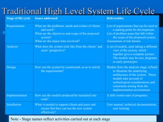
Traditional High Level System Life Cycle
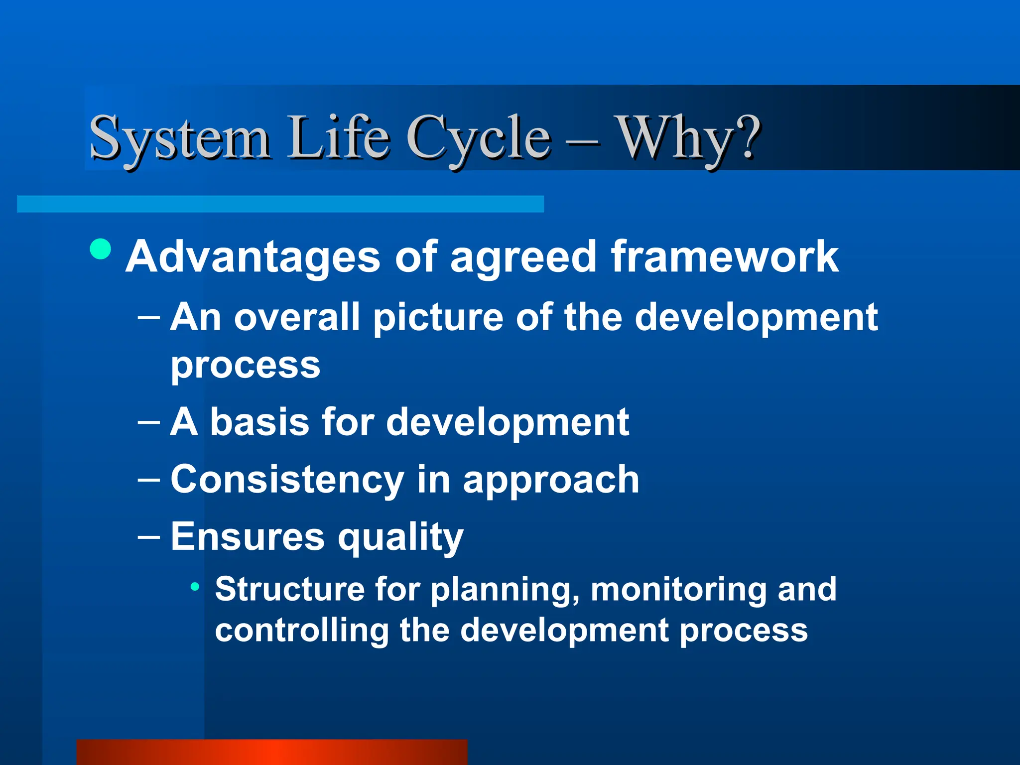
Stage of life cycle Issues addressed Deliverables
Requirements What are the problems, needs and wishes of clients
and users?
What are the objectives and scope of the proposed
system?
What are the major risks involved?
List of requirements that can be used as
a starting point for development.
List of problem areas that fall within
the scope of the proposed system.
Assessment of risk factors.
Analysis What does the system look like from the clients’ and
users’ perspective?
A set of models, each taking a different
view of the system, which
together give a complete picture.
The models may be text, diagrams
or early prototypes.
Design How can the system be constructed, so as to satisfy
the requirements?
Models from the analysis stage, refined
to illustrate the underlying
architecture of the system. These
models take account of
technological considerations and
constraints arising from the
implementation environment.
Implementation How can the models produced be translated into
code?
A fully tested suite of programs.
Installation What is needed to support clients and users and
ensure that they can use the new system
effectively?
User manual, technical documentation,
user training.
Note - Stage names reflect activities carried out at each stage
6.
Problems with TraditionalApproach
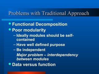
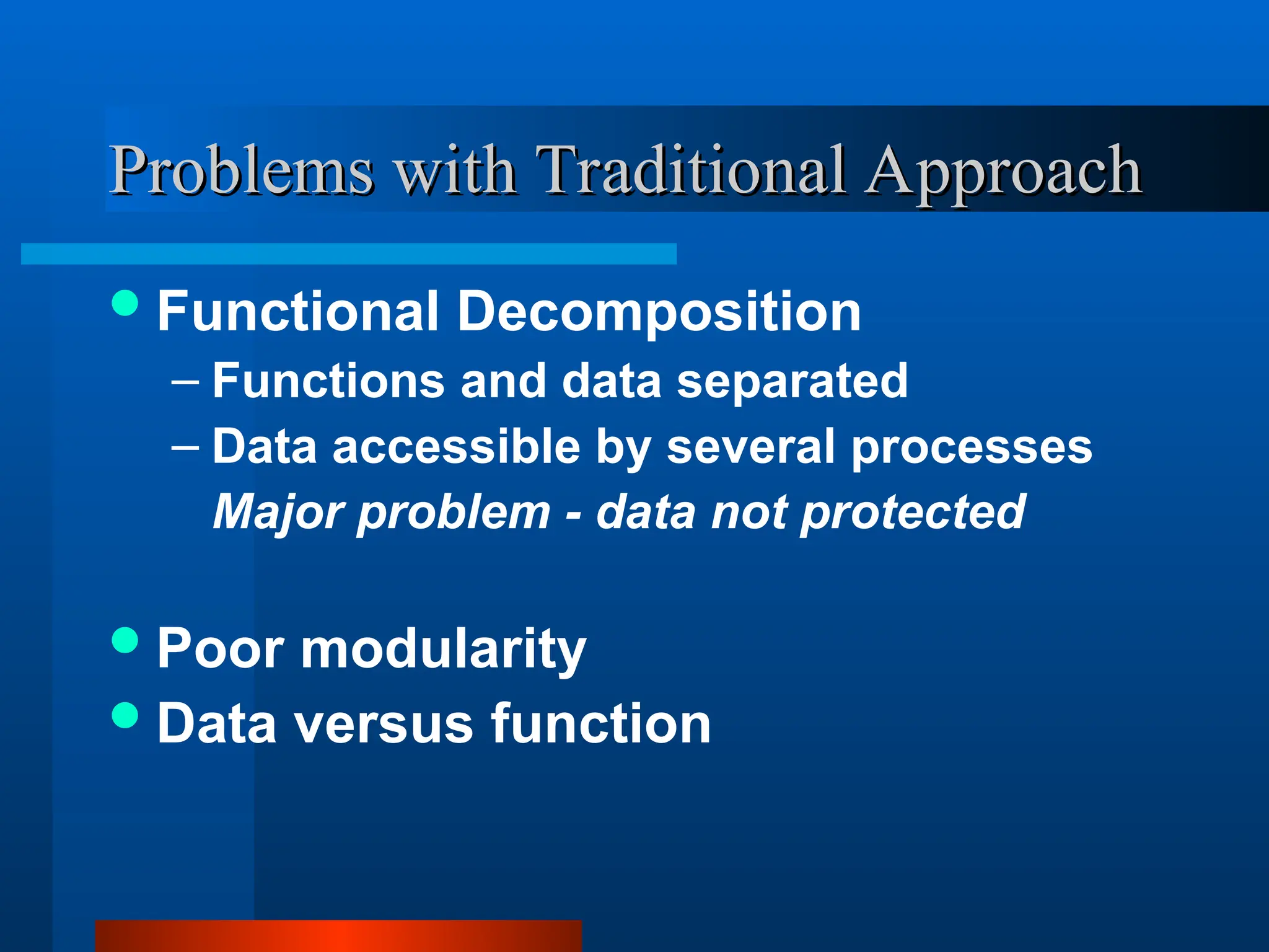
Problems with Traditional Approach
Functional Decomposition
– Functions and data separated
– Data accessible by several processes
Major problem - data not protected
Poor modularity
Data versus function
7.
Problems with TraditionalApproach
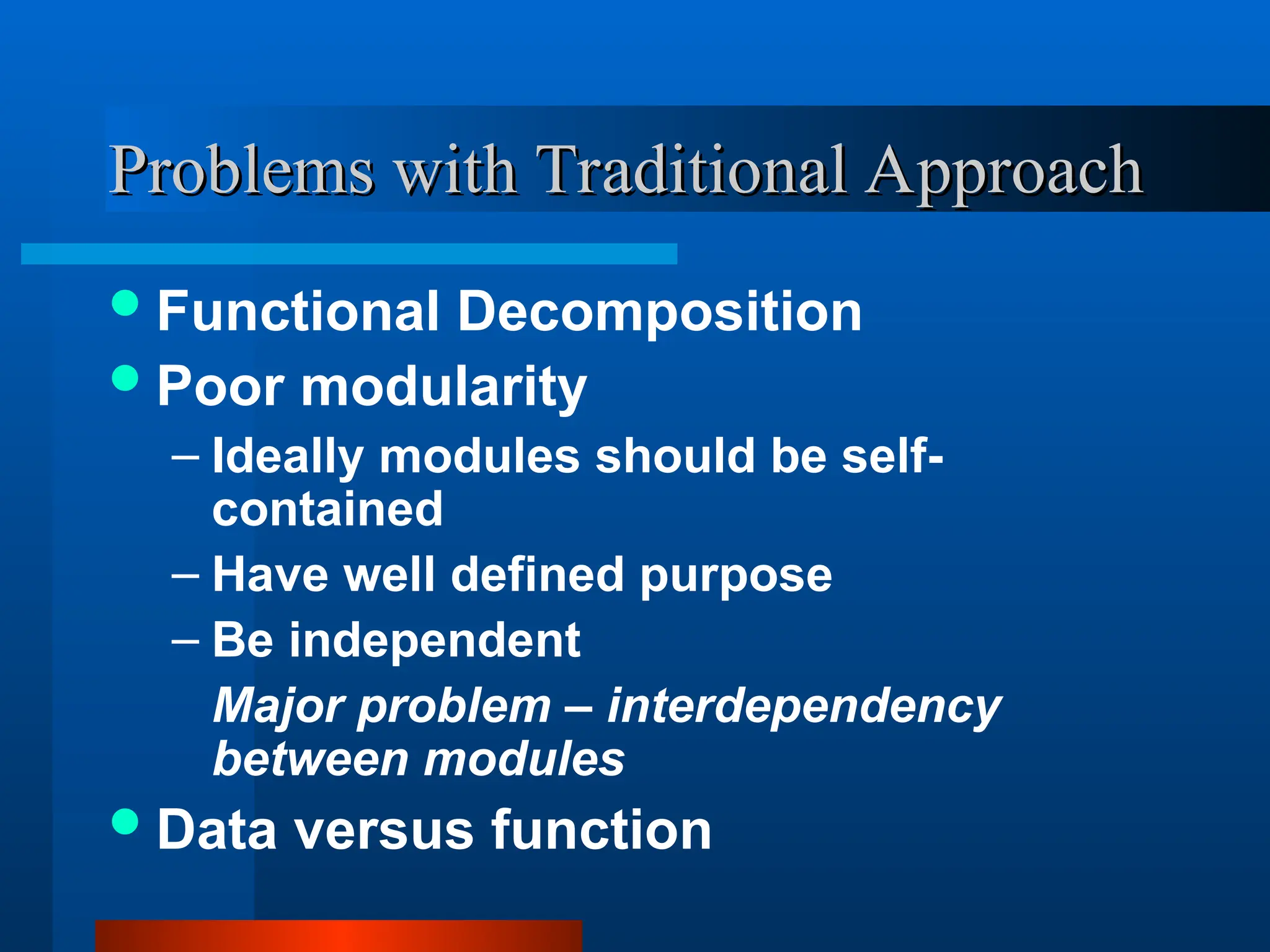
Problems with Traditional Approach
Functional Decomposition
Poor modularity
– Ideally modules should be self-
contained
– Have well defined purpose
– Be independent
Major problem – interdependency
between modules
Data versus function
8.
Problems with TraditionalApproach
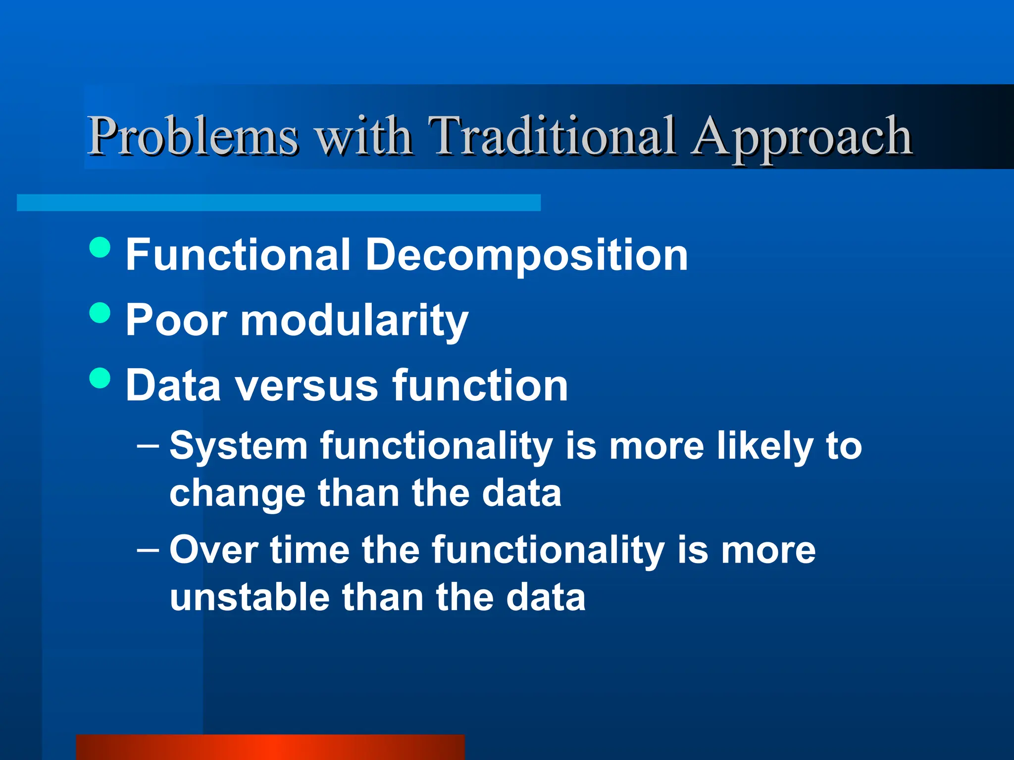
Problems with Traditional Approach
Functional Decomposition
Poor modularity
Data versus function
– System functionality is more likely to
change than the data
– Over time the functionality is more
unstable than the data
9.
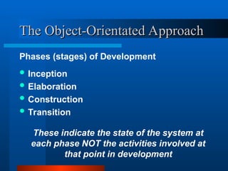
The Object-Orientated Approach
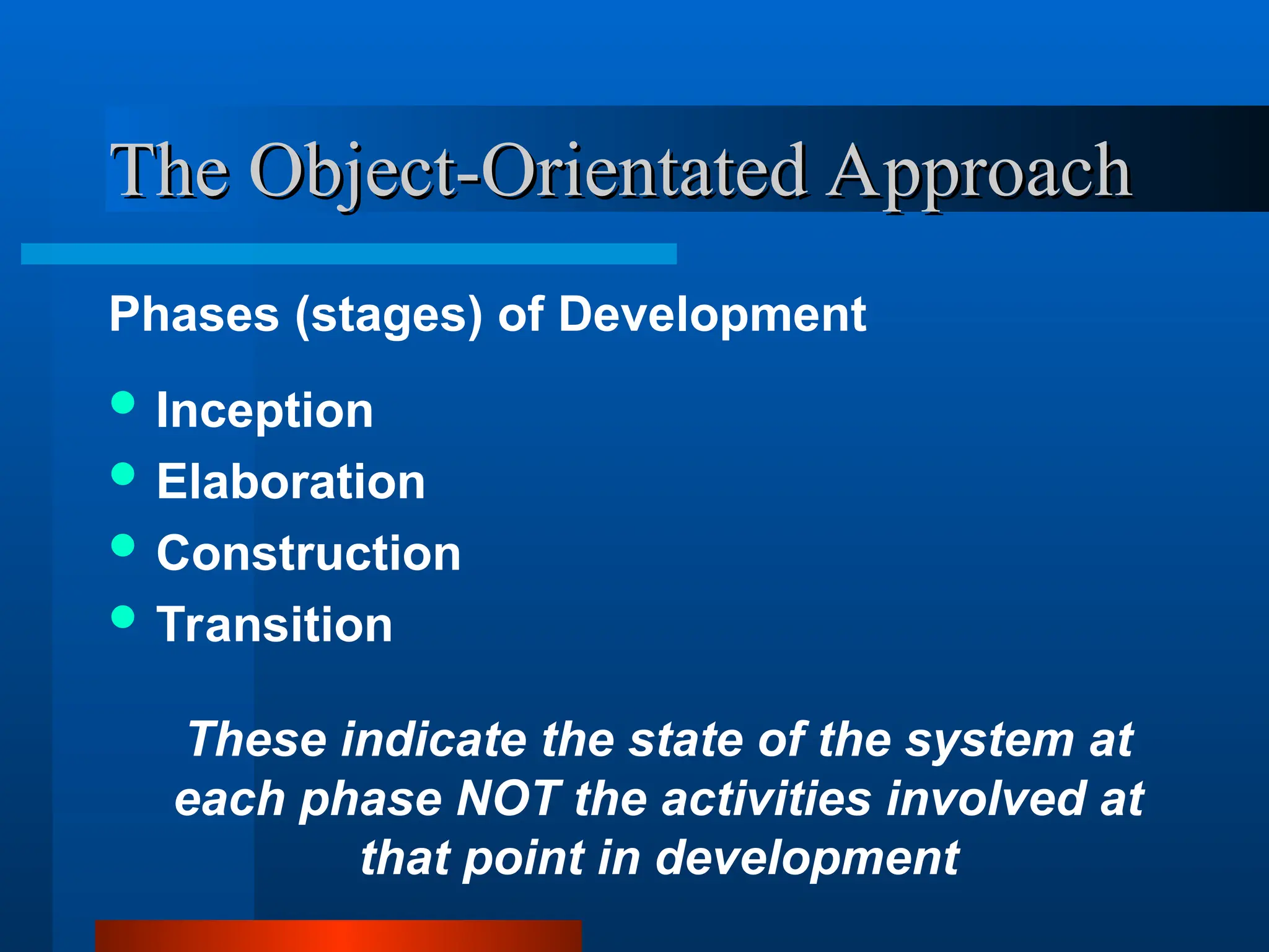
TheObject-Orientated Approach
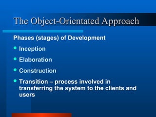
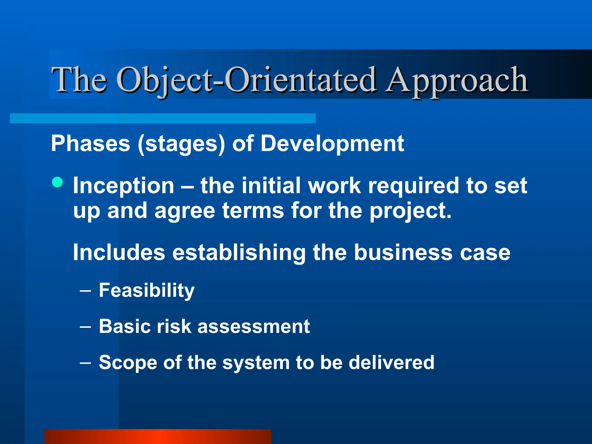
Phases (stages) of Development
Inception
Elaboration
Construction
Transition
These indicate the state of the system at
each phase NOT the activities involved at
that point in development
10.
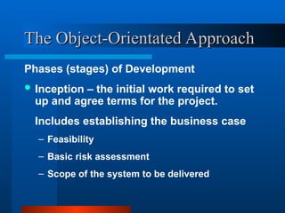
The Object-Orientated Approach
TheObject-Orientated Approach
Phases (stages) of Development
Inception – the initial work required to set
up and agree terms for the project.
Includes establishing the business case
– Feasibility
– Basic risk assessment
– Scope of the system to be delivered
11.
The Object-Orientated Approach
TheObject-Orientated Approach
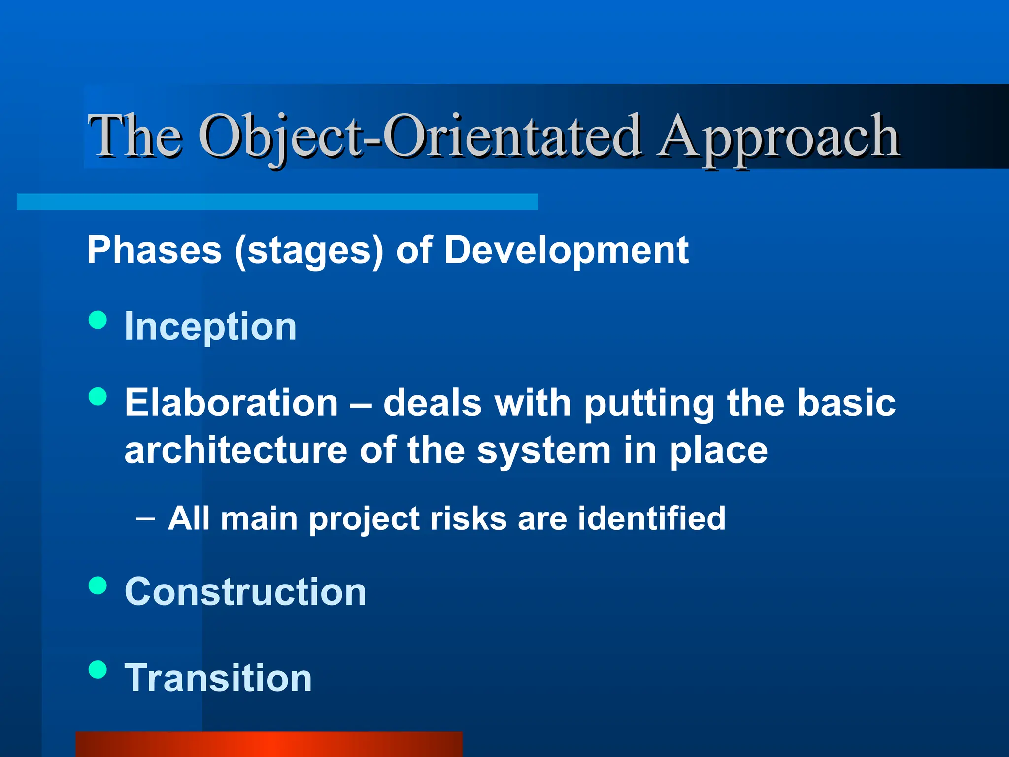
Phases (stages) of Development
Inception
Elaboration – deals with putting the basic
architecture of the system in place
– All main project risks are identified
Construction
Transition
12.
The Object-Orientated Approach
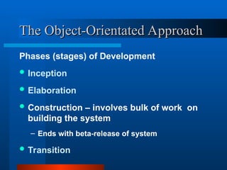
TheObject-Orientated Approach
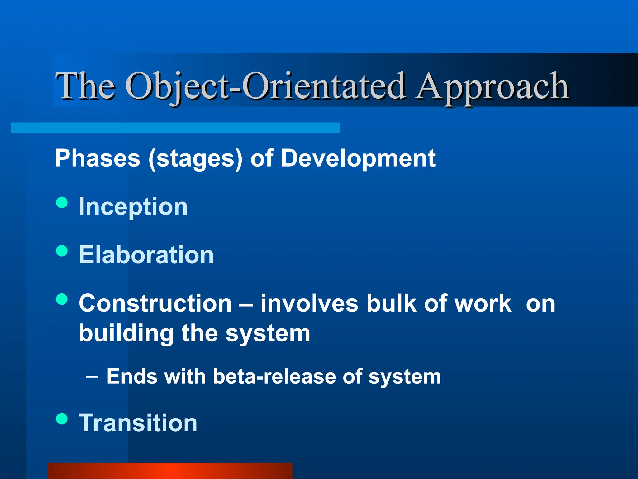
Phases (stages) of Development
Inception
Elaboration
Construction – involves bulk of work on
building the system
– Ends with beta-release of system
Transition
13.
The Object-Orientated Approach
TheObject-Orientated Approach
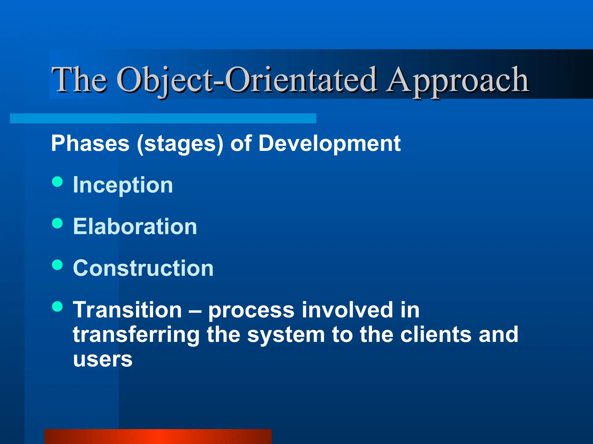
Phases (stages) of Development
Inception
Elaboration
Construction
Transition – process involved in
transferring the system to the clients and
users
14.
Workflows
Workflows
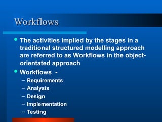
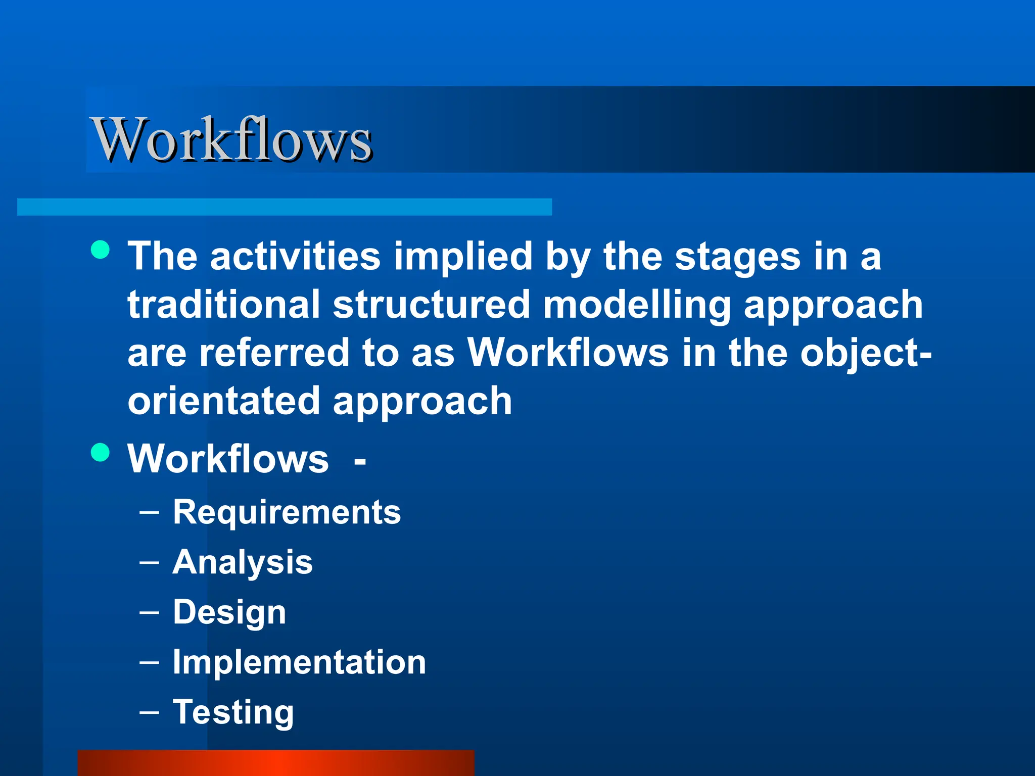
The activitiesimplied by the stages in a
traditional structured modelling approach
are referred to as Workflows in the object-
orientated approach
Workflows -
– Requirements
– Analysis
– Design
– Implementation
– Testing
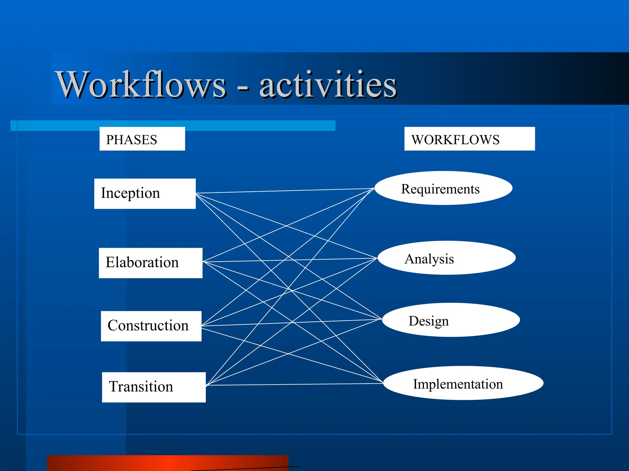
The Object-Orientated Approach
TheObject-Orientated Approach
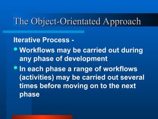
Iterative Process -
Workflows may be carried out during
any phase of development
In each phase a range of workflows
(activities) may be carried out several
times before moving on to the next
phase
17.
The Object-Orientated Approach
TheObject-Orientated Approach
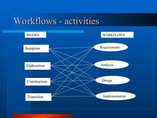
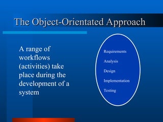
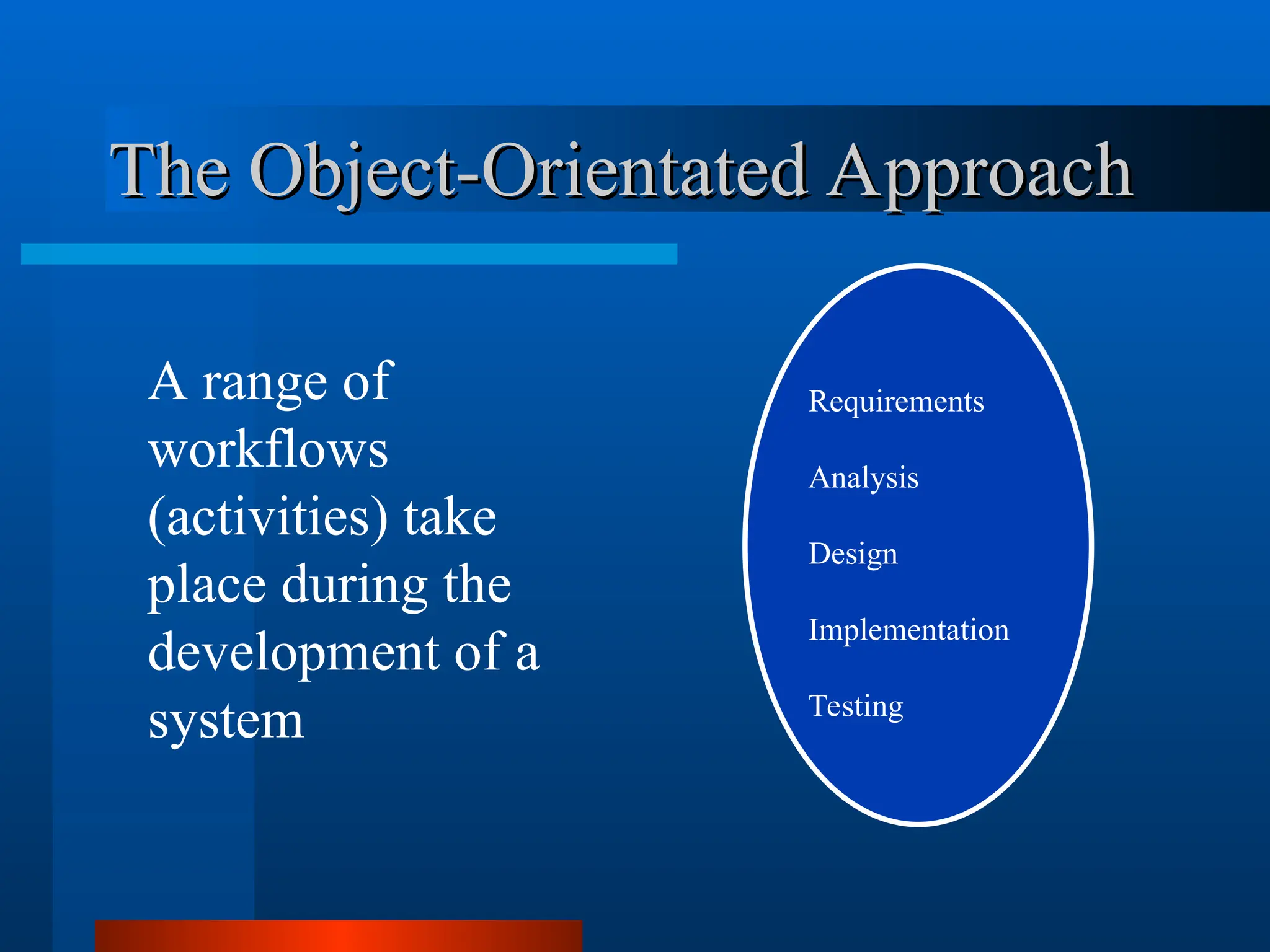
A range of
workflows
(activities) take
place during the
development of a
system
Requirements
Analysis
Design
Implementation
Testing
18.
The Object-Orientated Approach
TheObject-Orientated Approach
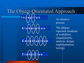
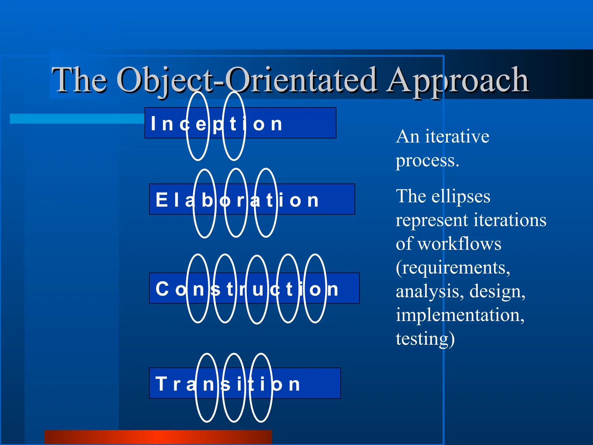
I n c e p t i o n
E l a b o r a t i o n
C o n s t r u c t i o n
T r a n s i t i o n
An iterative
process.
The ellipses
represent iterations
of workflows
(requirements,
analysis, design,
implementation,
testing)
19.
A seamless DevelopmentProcess
Phases less distinct than in a
structured approach
Difficult to say when one phase ends
and another begins
Driven by a single unifying idea – the
object
The Object-Orientated Approach
The Object-Orientated Approach
20.
The Object
The Object
Basicbuilding block
Objects in the real world translate
into objects in the software system
– Physical (customers, products)
– Conceptual (orders, reservations
– Organisation (companies, departments)
– Implementation (GUI Windows)
21.
The foundation ofall development
work is the object
No new system models introduced at
different stages
Early models developed and refined
through the development process
An iterative design process
The Object-Orientated Approach
The Object-Orientated Approach
22.
Modelling
Modelling
To capture thewhole of a system we
need to view it from different aspects
Each diagram provides some but not
all of the information – abstraction
Each model is an abstraction of the
complete system
System is broken down into small
workable chunks - decomposition
23.
Unified Modelling Language- UML
Unified Modelling Language - UML
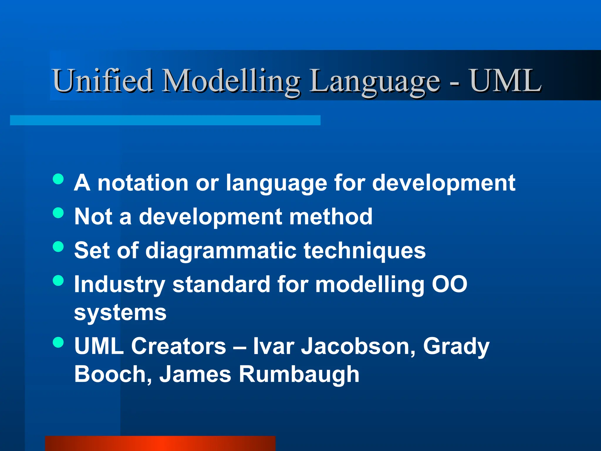
A notation or language for development
Not a development method
Set of diagrammatic techniques
Industry standard for modelling OO
systems
UML Creators – Ivar Jacobson, Grady
Booch, James Rumbaugh
24.
Principal UML Models
PrincipalUML Models
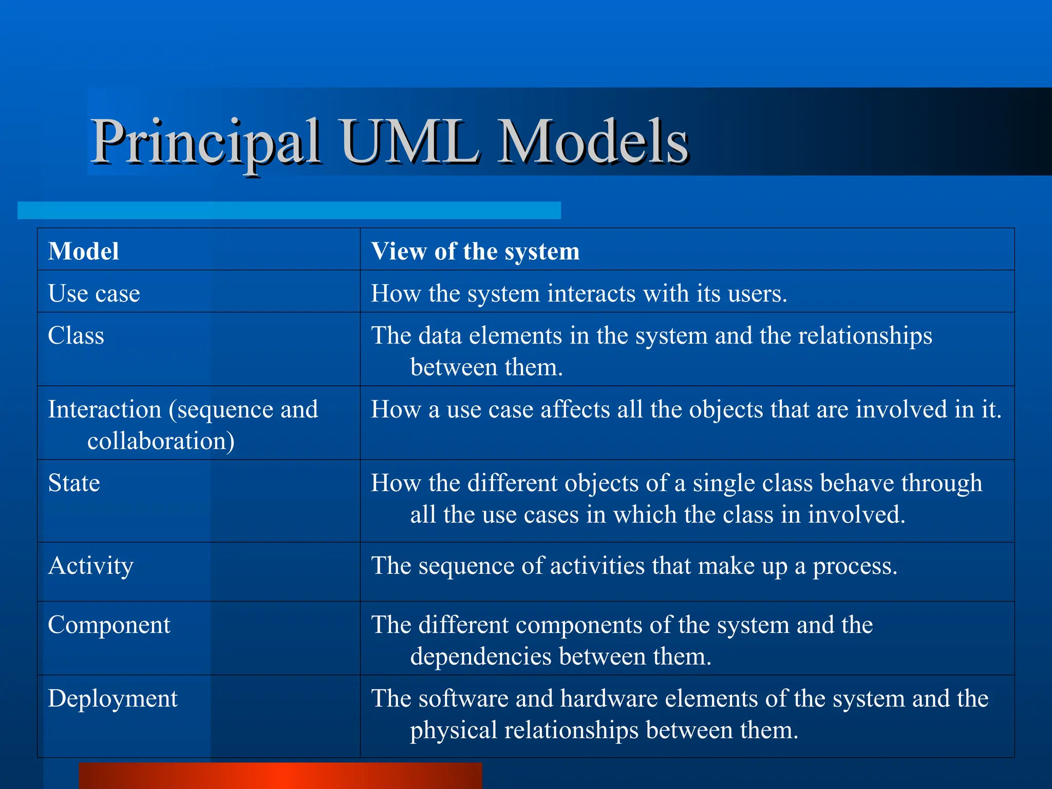
Model View of the system
Use case How the system interacts with its users.
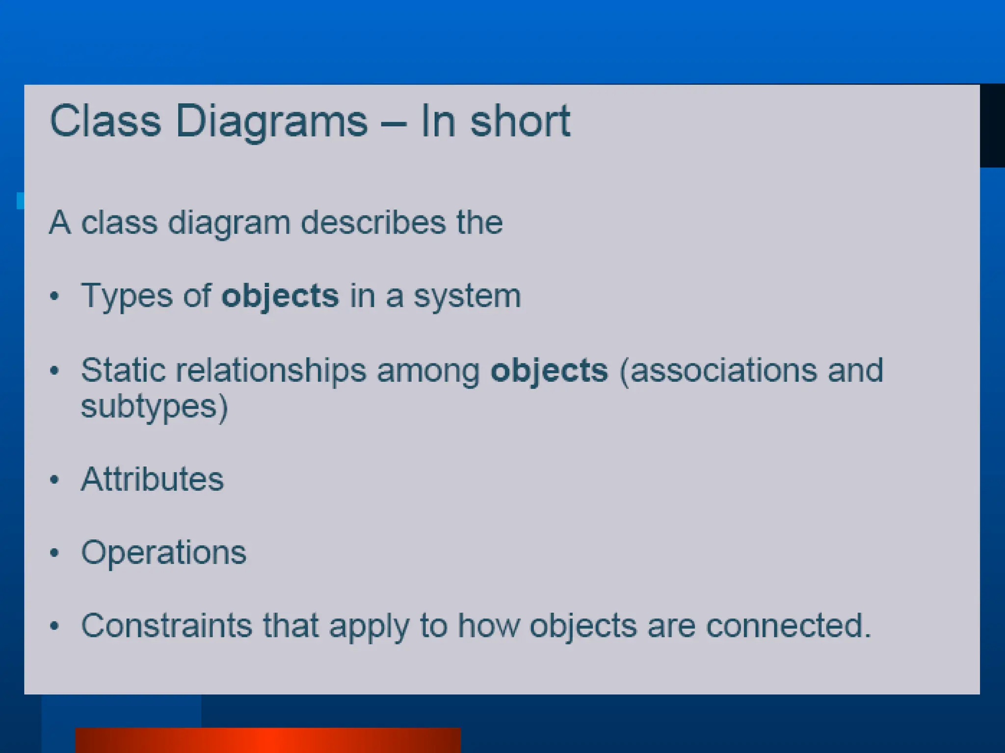
Class The data elements in the system and the relationships
between them.
Interaction (sequence and
collaboration)
How a use case affects all the objects that are involved in it.
State How the different objects of a single class behave through
all the use cases in which the class in involved.
Activity The sequence of activities that make up a process.
Component The different components of the system and the
dependencies between them.
Deployment The software and hardware elements of the system and the
physical relationships between them.
25.
The UML ProvidesStandardized
The UML Provides Standardized
Diagrams
Diagrams
Deployment
Diagram
Use Case
Diagrams
Use Case
Diagrams
Use Case
Diagrams
Scenario
Diagrams
Scenario
Diagrams
Sequence
Diagrams
State
Diagrams
State
Diagrams
State
Diagrams
Component
Diagrams
Component
Diagrams
Component
Diagrams
Model
State
Diagrams
State
Diagrams
Object
Diagrams
Scenario
Diagrams
Scenario
Diagrams
Collaboration
Diagrams
Use Case
Diagrams
Use Case
Diagrams
Activity
Diagrams
State
Diagrams
State
Diagrams
Class
Diagrams
UML in OneSentence
UML in One Sentence
The UML is a graphical language for
visualizing
specifying
constructing
documenting
artifacts of a software-intensive system.
28.
Visualizing
Visualizing
explicit model facilitatescommunication
some structures transcend (pass or more)
what can be represented in programming
language
each symbol has well-defined semantics
behind it
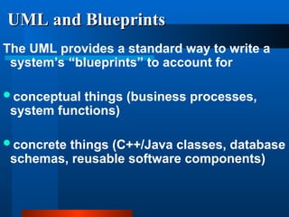
UML and Blueprints
UMLand Blueprints
The UML provides a standard way to write a
system’s “blueprints” to account for
conceptual things (business processes,
system functions)
concrete things (C++/Java classes, database
schemas, reusable software components)
32.
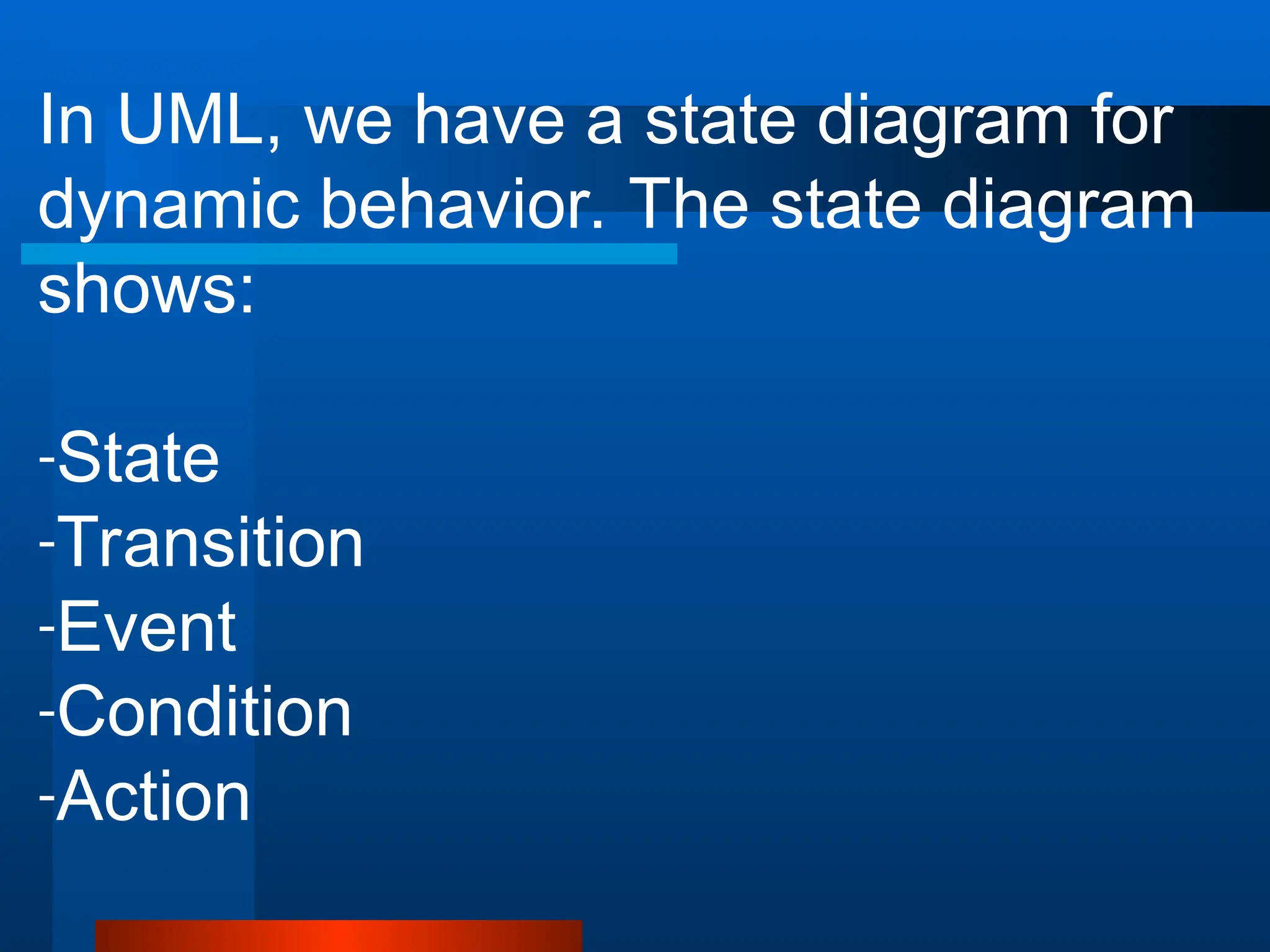
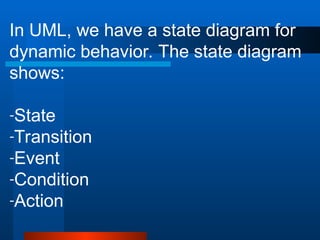
In UML, wehave a state diagram for
dynamic behavior. The state diagram
shows:
-State
-Transition
-Event
-Condition
-Action
33.
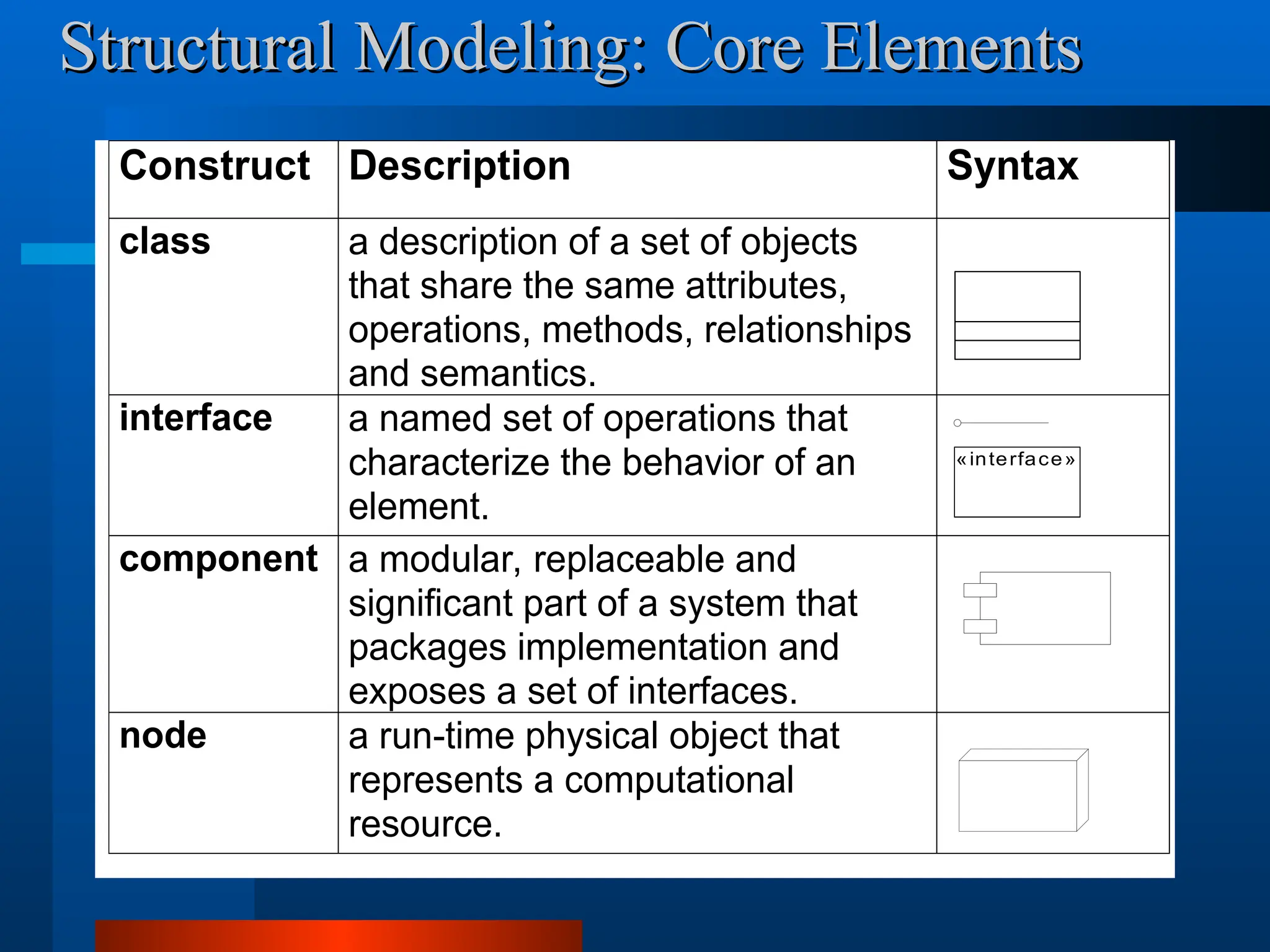
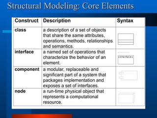
Construct Description Syntax
classa description of a set of objects
that share the same attributes,
operations, methods, relationships
and semantics.
interface a named set of operations that
characterize the behavior of an
element.
component a modular, replaceable and
significant part of a system that
packages implementation and
exposes a set of interfaces.
node a run-time physical object that
represents a computational
resource.
«interface»
Structural Modeling: Core Elements
Structural Modeling: Core Elements
34.
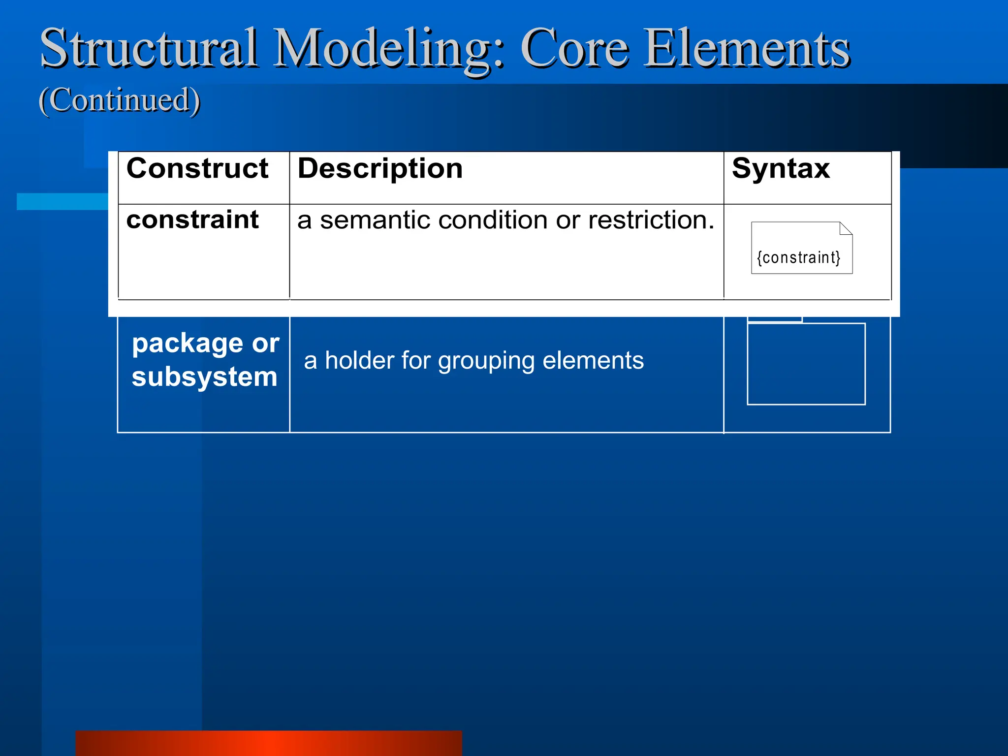
Structural Modeling: CoreElements
Structural Modeling: Core Elements
(Continued)
(Continued)
Construct Description Syntax
constraint a semantic condition or restriction.
{constraint}
package or
subsystem
a holder for grouping elements
35.
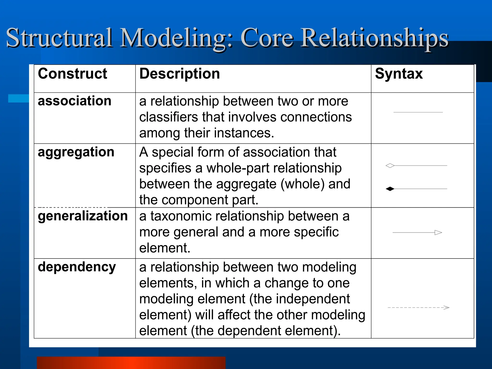
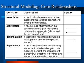
Construct Description Syntax
associationa relationship between two or more
classifiers that involves connections
among their instances.
aggregation A special form of association that
specifies a whole-part relationship
between the aggregate (whole) and
the component part.
generalization a taxonomic relationship between a
more general and a more specific
element.
dependency a relationship between two modeling
elements, in which a change to one
modeling element (the independent
element) will affect the other modeling
element (the dependent element).
Structural Modeling: Core Relationships
Structural Modeling: Core Relationships
(open arrow)
Composition
36.
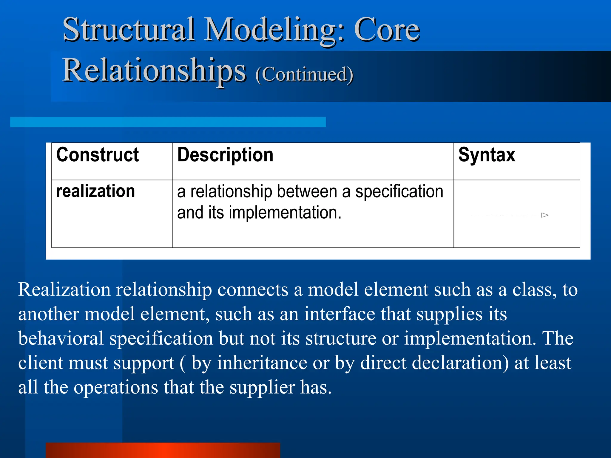
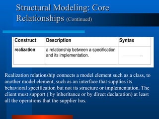
Construct Description Syntax
realizationa relationship between a specification
and its implementation.
Structural Modeling: Core
Structural Modeling: Core
Relationships
Relationships (Continued)
(Continued)
(closed arrow)
Realization relationship connects a model element such as a class, to
another model element, such as an interface that supplies its
behavioral specification but not its structure or implementation. The
client must support ( by inheritance or by direct declaration) at least
all the operations that the supplier has.
38.
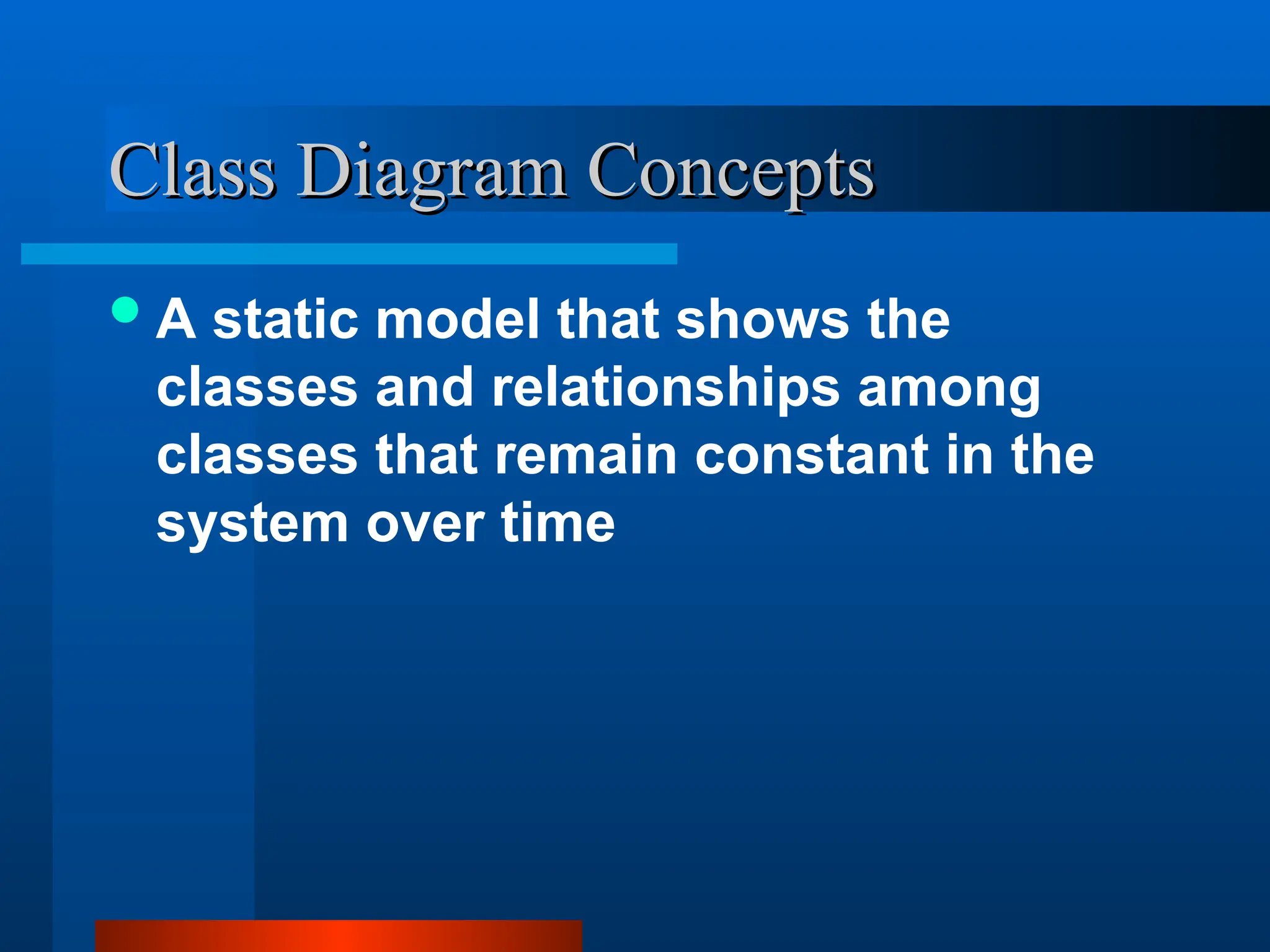
Class Diagram Concepts
ClassDiagram Concepts
A static model that shows the
classes and relationships among
classes that remain constant in the
system over time
39.
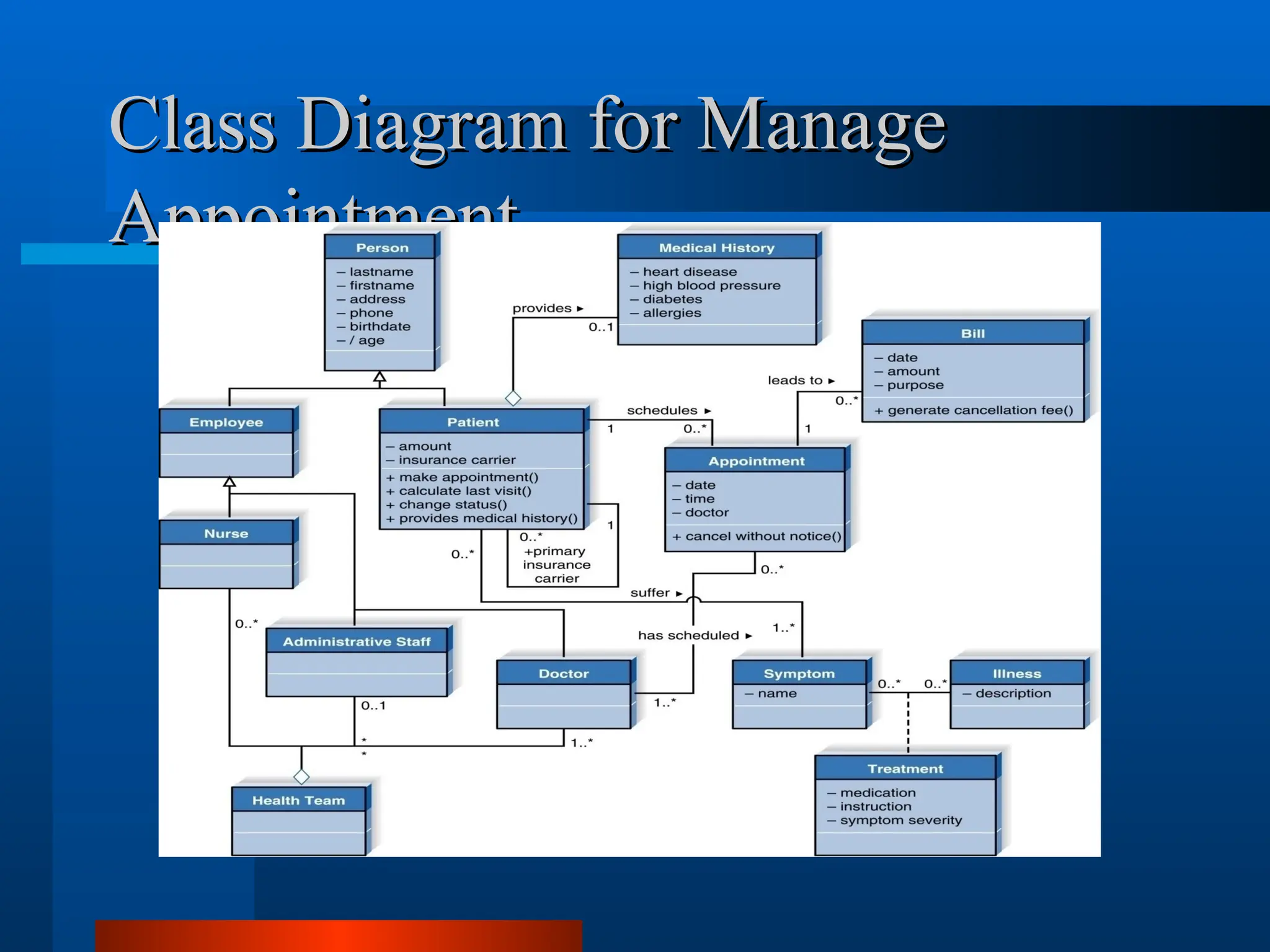
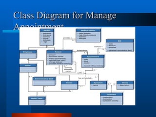
Class Diagram forManage
Class Diagram for Manage
Appointment
Appointment
40.
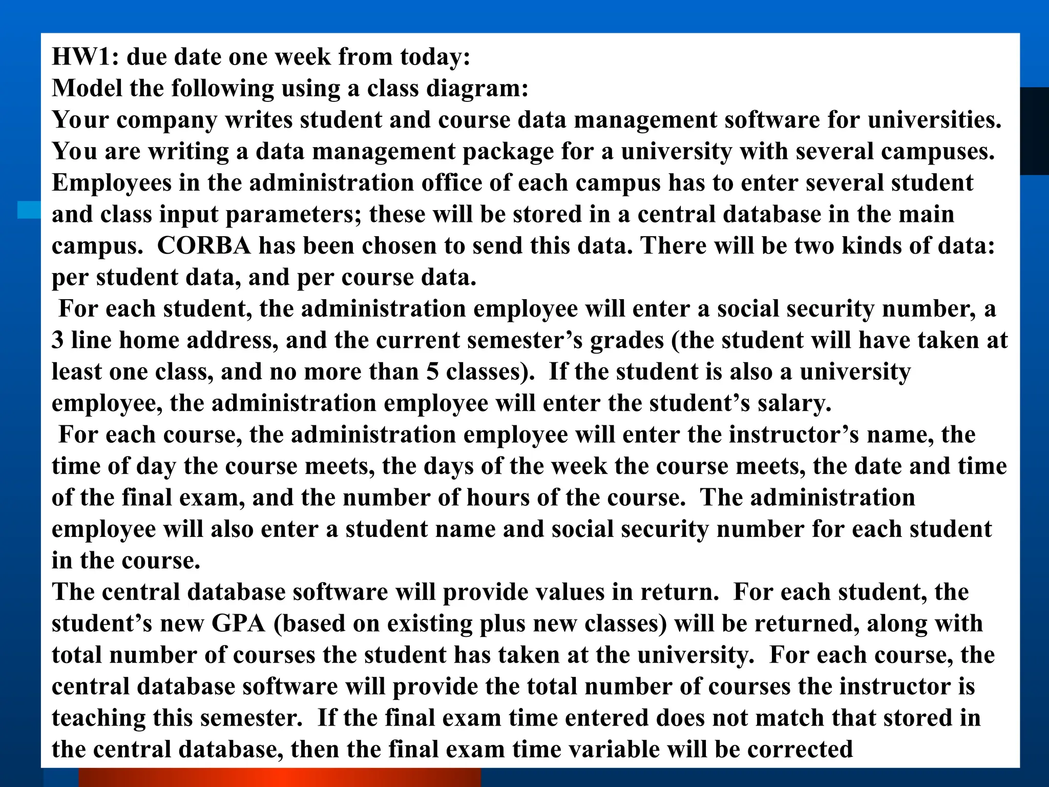
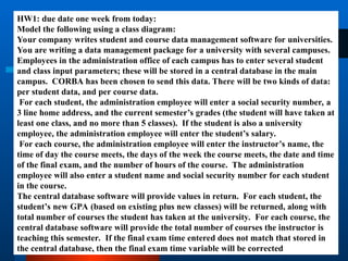
HW1: due dateone week from today:
Model the following using a class diagram:
Your company writes student and course data management software for universities.
You are writing a data management package for a university with several campuses.
Employees in the administration office of each campus has to enter several student
and class input parameters; these will be stored in a central database in the main
campus. CORBA has been chosen to send this data. There will be two kinds of data:
per student data, and per course data.
For each student, the administration employee will enter a social security number, a
3 line home address, and the current semester’s grades (the student will have taken at
least one class, and no more than 5 classes). If the student is also a university
employee, the administration employee will enter the student’s salary.
For each course, the administration employee will enter the instructor’s name, the
time of day the course meets, the days of the week the course meets, the date and time
of the final exam, and the number of hours of the course. The administration
employee will also enter a student name and social security number for each student
in the course.
The central database software will provide values in return. For each student, the
student’s new GPA (based on existing plus new classes) will be returned, along with
total number of courses the student has taken at the university. For each course, the
central database software will provide the total number of courses the instructor is
teaching this semester. If the final exam time entered does not match that stored in
the central database, then the final exam time variable will be corrected
41.
Further reading
Further reading
Bennett, S., McRobb, S. and Farmer, R. Object-Oriented Systems
Analysis and Design Using UML, 2nd Ed, London: McGraw-Hill,
2002.
Brown, D. Object-Oriented Analysis: objects in plain English, New
York: John Wiley, 1997.
Fowler, M. UML Distilled: a brief guide to the standard object
modeling language, 2nd Ed, Reading Massachusetts: Addison-
Wesley, 2000.
Jacobson, I. Object-Oriented Software Engineering: A Use Case
Driven Approach, Wokingham, England: Addison-Wesley, 1992.
Larman, C. Applying UML and patterns: an introduction to object-
oriented analysis and design, New Jersey: Prentice Hall, 1998.
Stevens, P., with Pooley, R. Using UML. Software Engineering
with Objects and Components Updated edition, Harlow: Addison-
Wesley, 2000.
Editor's Notes
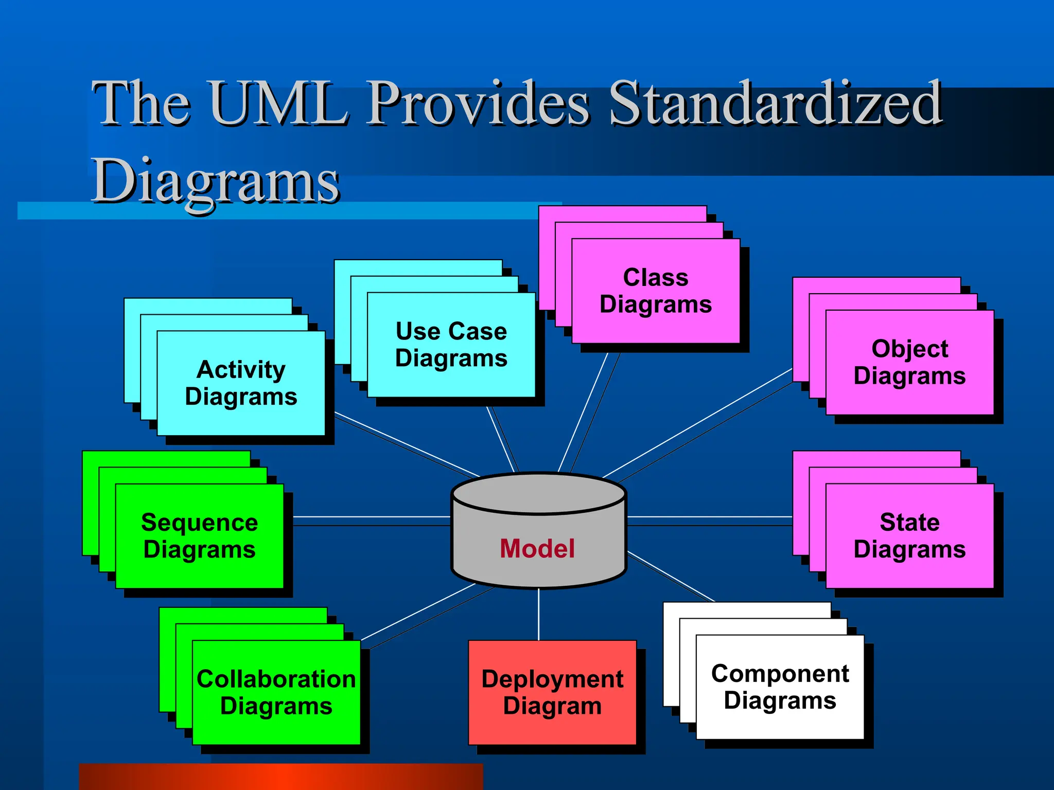
#26 In building a visual model of a system, many different diagrams are needed to represent different views of the system. The UML provides a rich notation for visualizing our models. This includes the following key diagrams:
Use Case diagrams to illustrate user interactions with the system.
Class diagrams to illustrate logical structure.
Object diagrams to illustrate objects and links.
State diagrams to illustrate behavior.
Component diagrams to illustrate physical structure of the software.
Deployment diagrams to show the mapping of software to hardware configurations.
Interaction diagrams (i.e., collaboration and sequence diagrams) to illustrate behavior.
Activity diagrams to illustrate the flow of events in a use case.
#27 Reasons UML does not define a process:
To increase the likelihood of widespread acceptance of a standard modeling notation without having to commit to a standard process.
There is a significant variability in what constitutes an appropriate process, depending on staff skills, research-development ration, nature of the problem, tools, and so-on.


![U
Unified
nified M
Modeling
odeling L
Language
anguage (
(UML)
UML)
“A graphical language for visualizing,
specifying, constructing, and documenting
the artifacts of a software intensive
system.” [Booch]](https://image.slidesharecdn.com/ch01-250929130905-2da2a52c/85/object-oriented-software-engineering-presentation-26-320.jpg)


![U
Unified
nified M
Modeling
odeling L
Language
anguage (
(UML)
UML)
“A graphical language for visualizing,
specifying, constructing, and documenting
the artifacts of a software intensive
system.” [Booch]](https://image.slidesharecdn.com/ch01-250929130905-2da2a52c/75/object-oriented-software-engineering-presentation-26-2048.jpg)