Downloaded 772 times
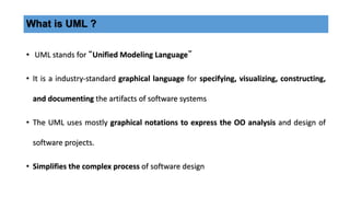

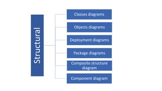
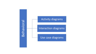
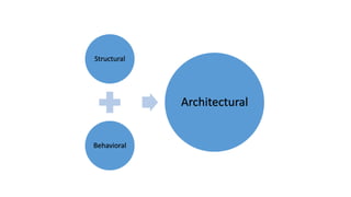

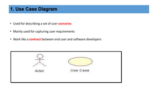
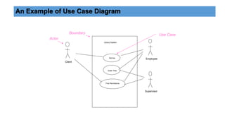

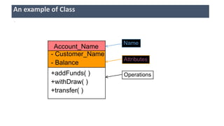
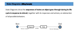

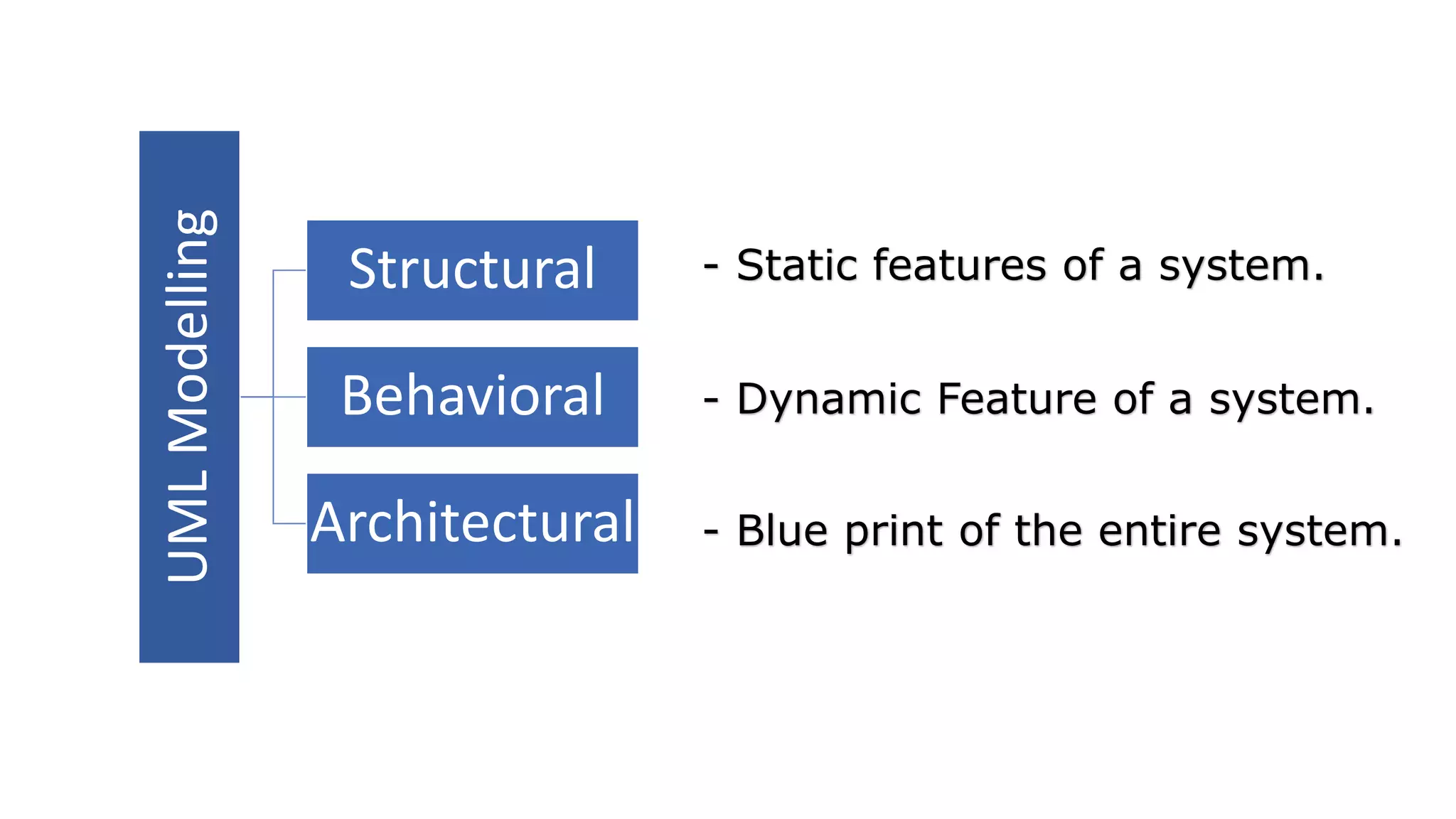
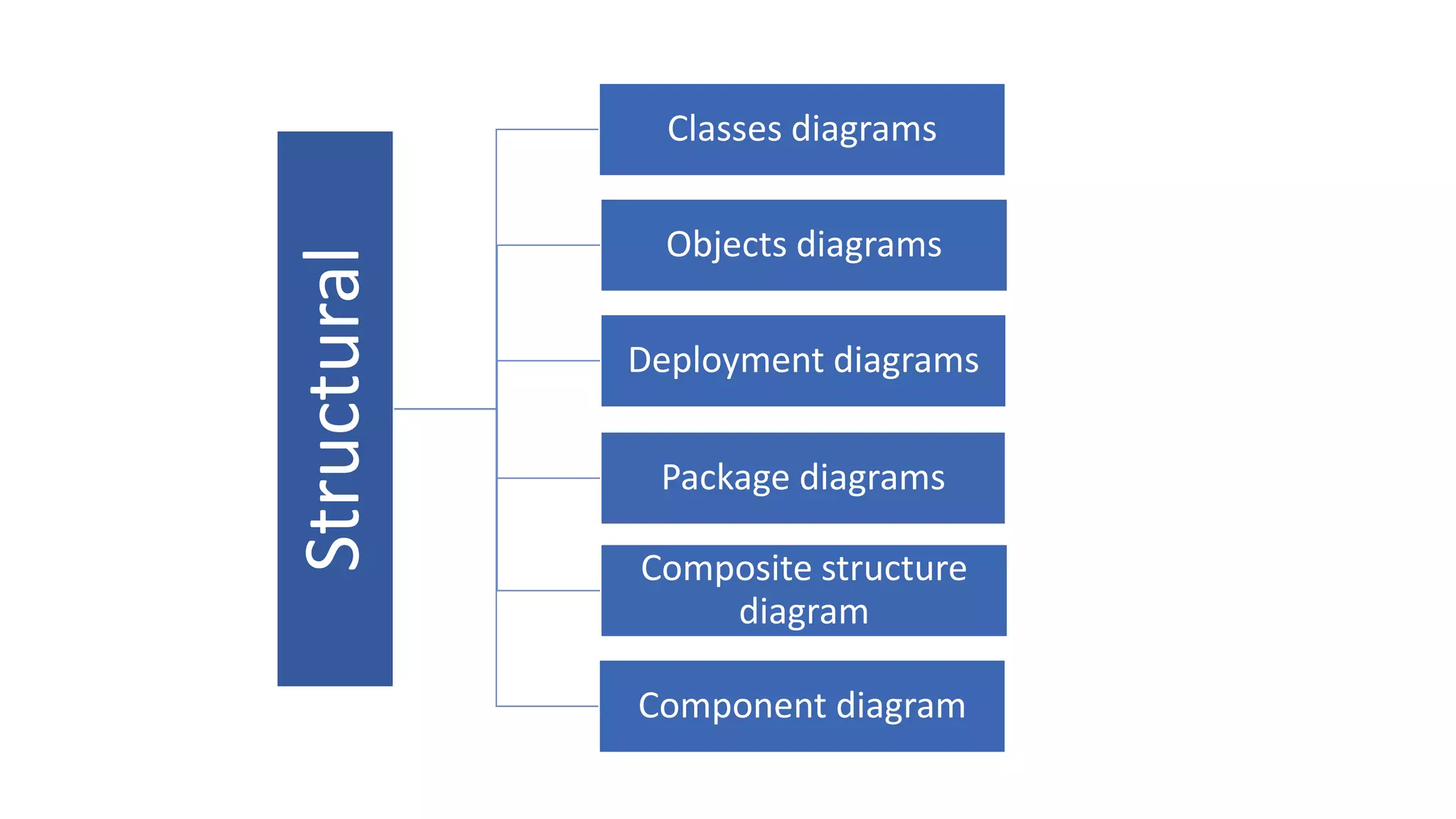
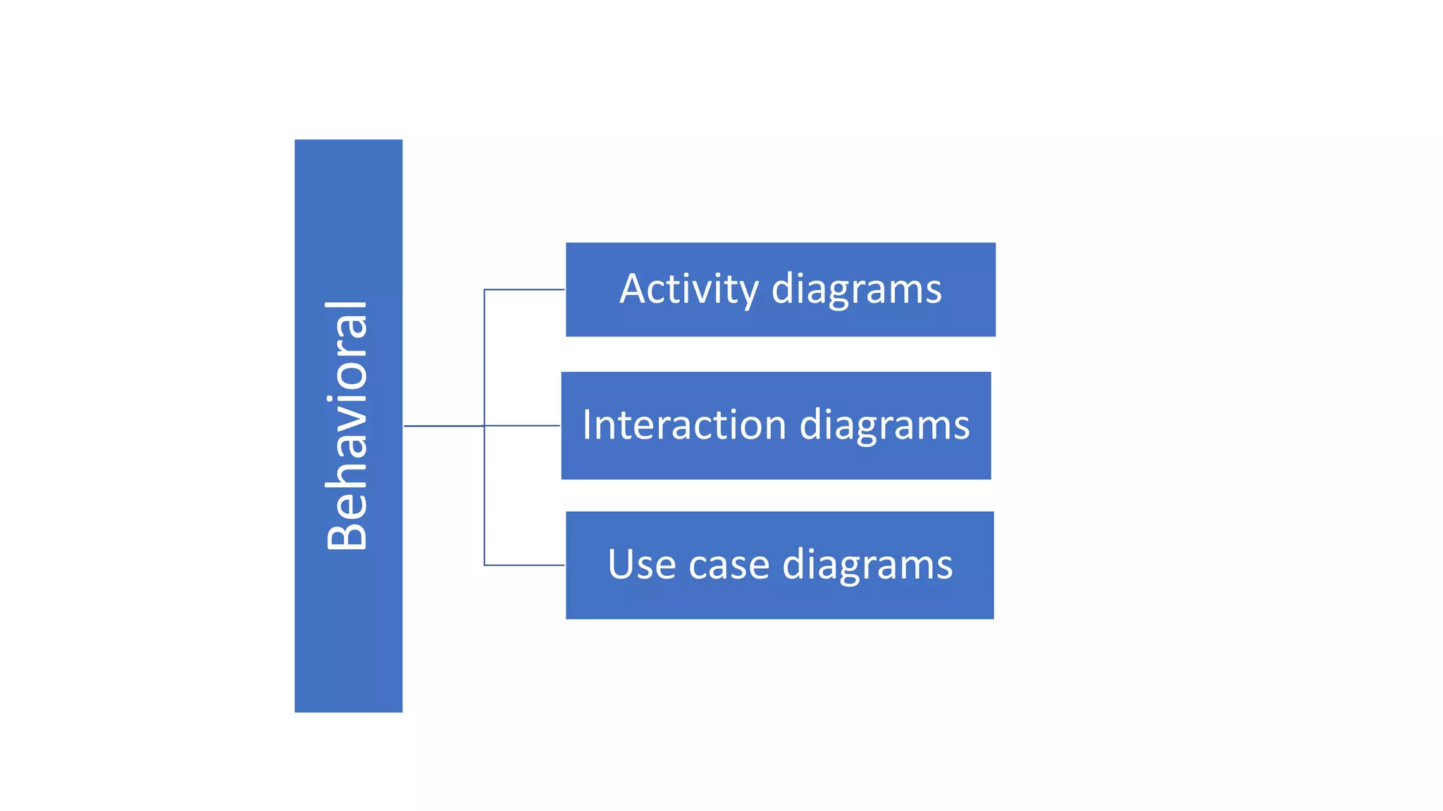

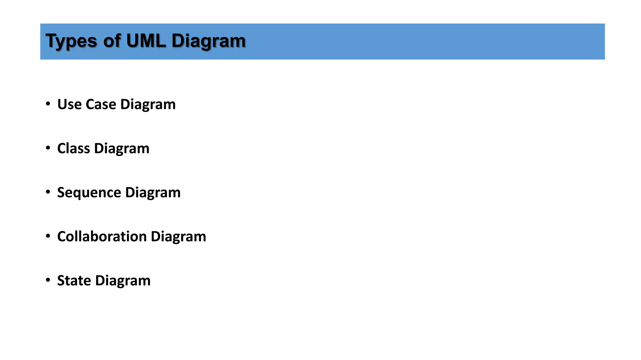
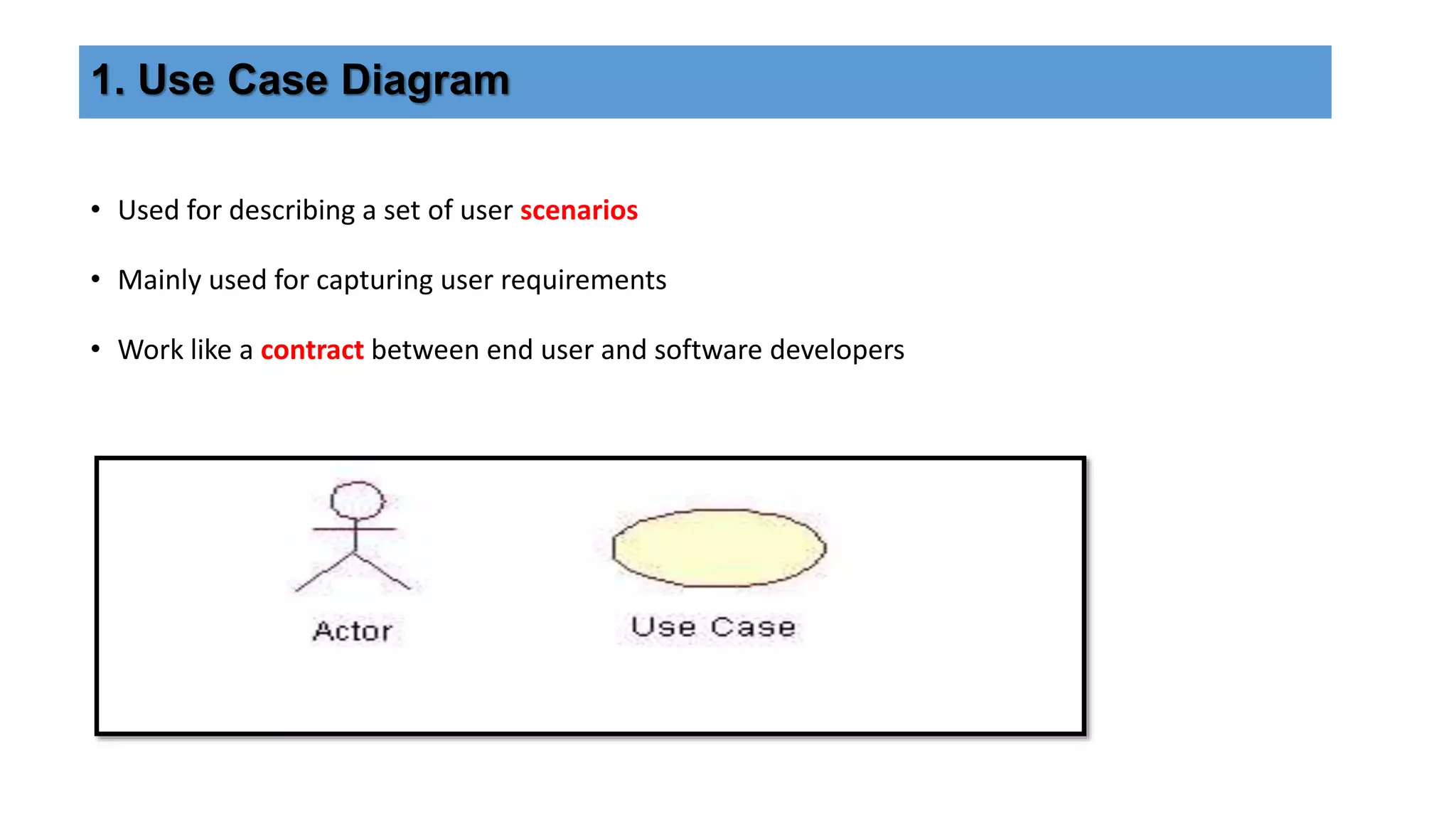
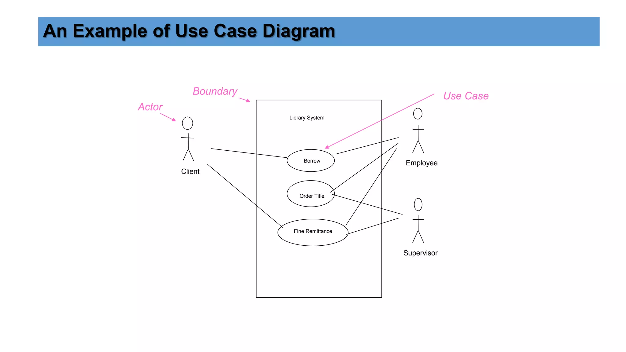
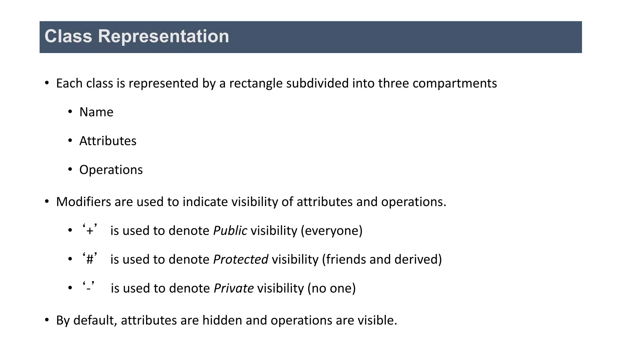


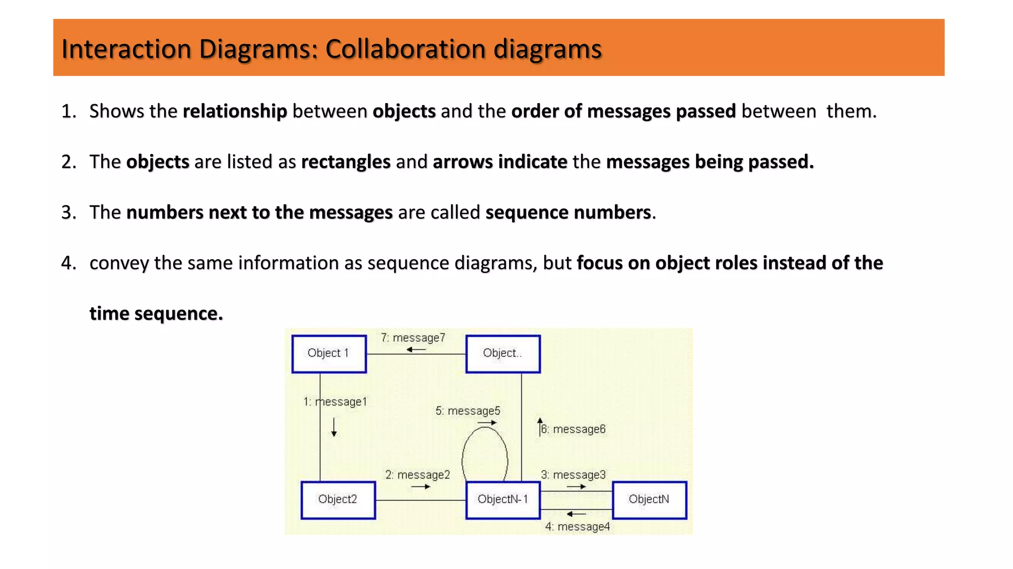


UML (Unified Modeling Language) is a standard modeling language used to specify, visualize, and document software systems. It uses graphical notations to model structural and behavioral aspects of a system. Common UML diagram types include use case diagrams, class diagrams, sequence diagrams, and state diagrams. Use case diagrams model user interactions, class diagrams show system entities and relationships, sequence diagrams visualize object interactions over time, and state diagrams depict object states and transitions. UML aims to simplify the complex process of software design through standardized modeling.


