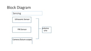
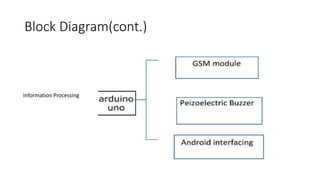
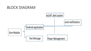
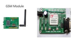
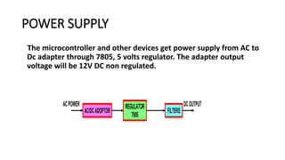
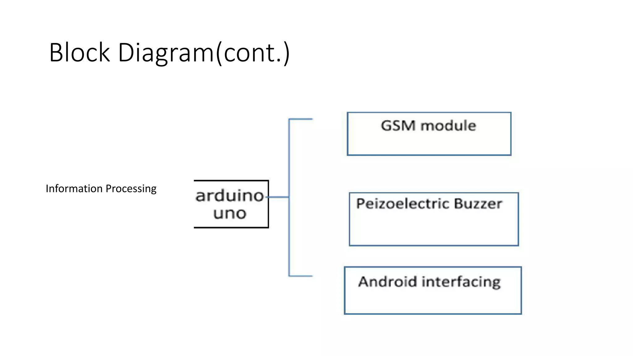
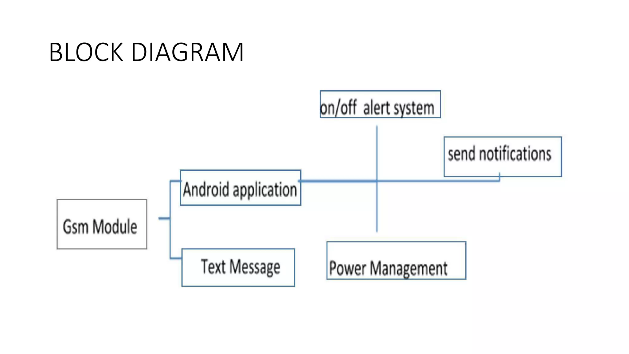
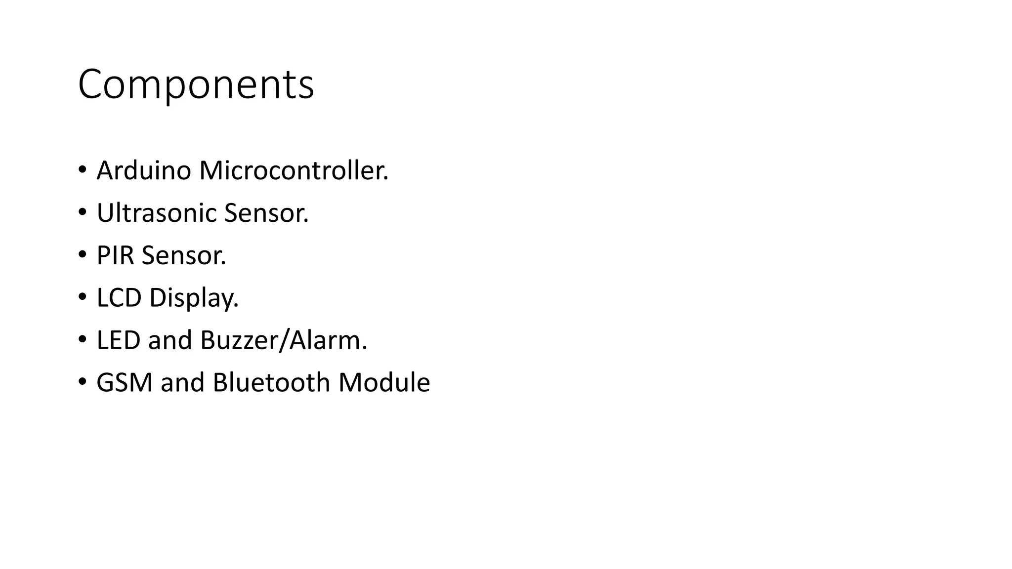
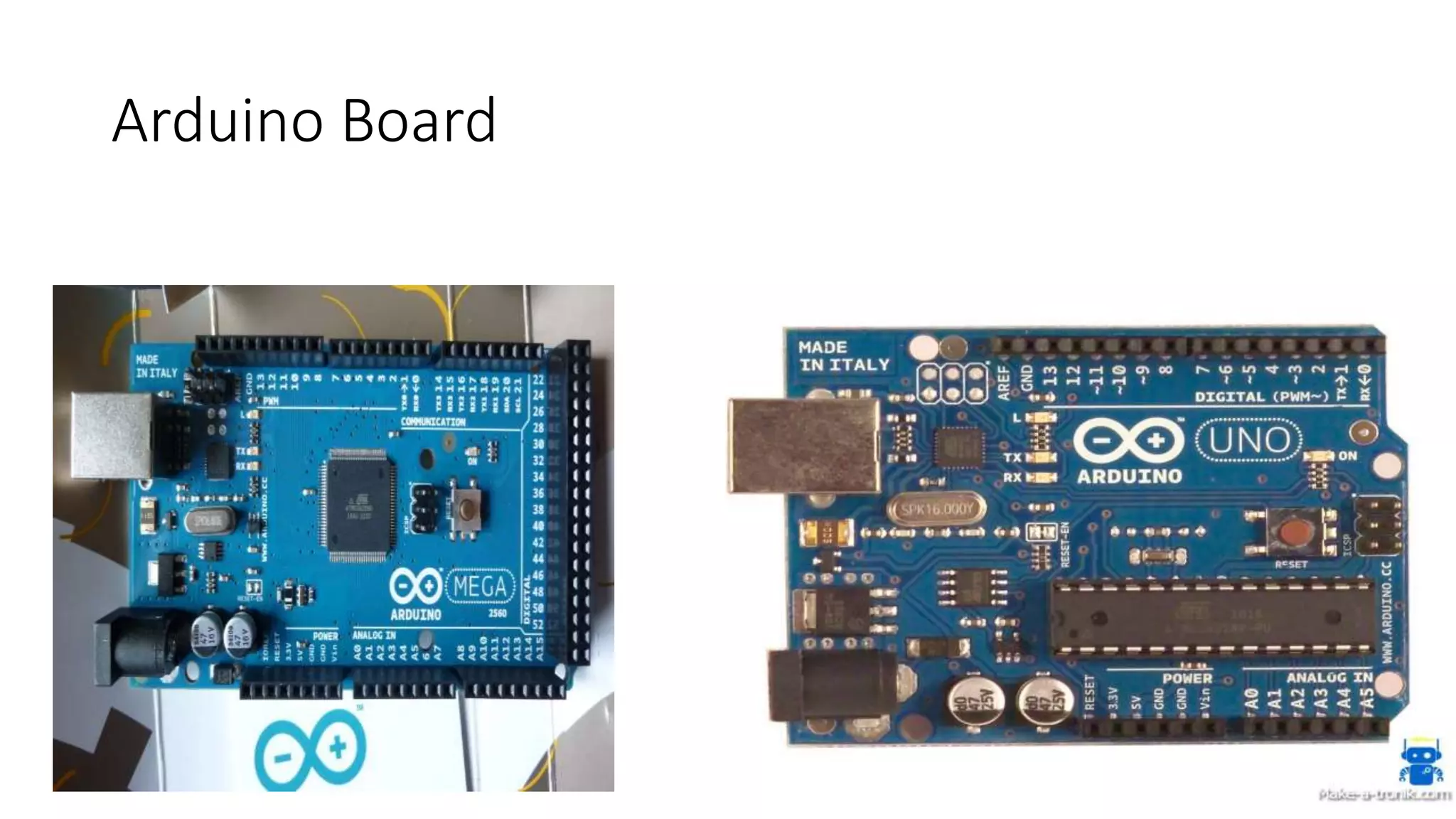
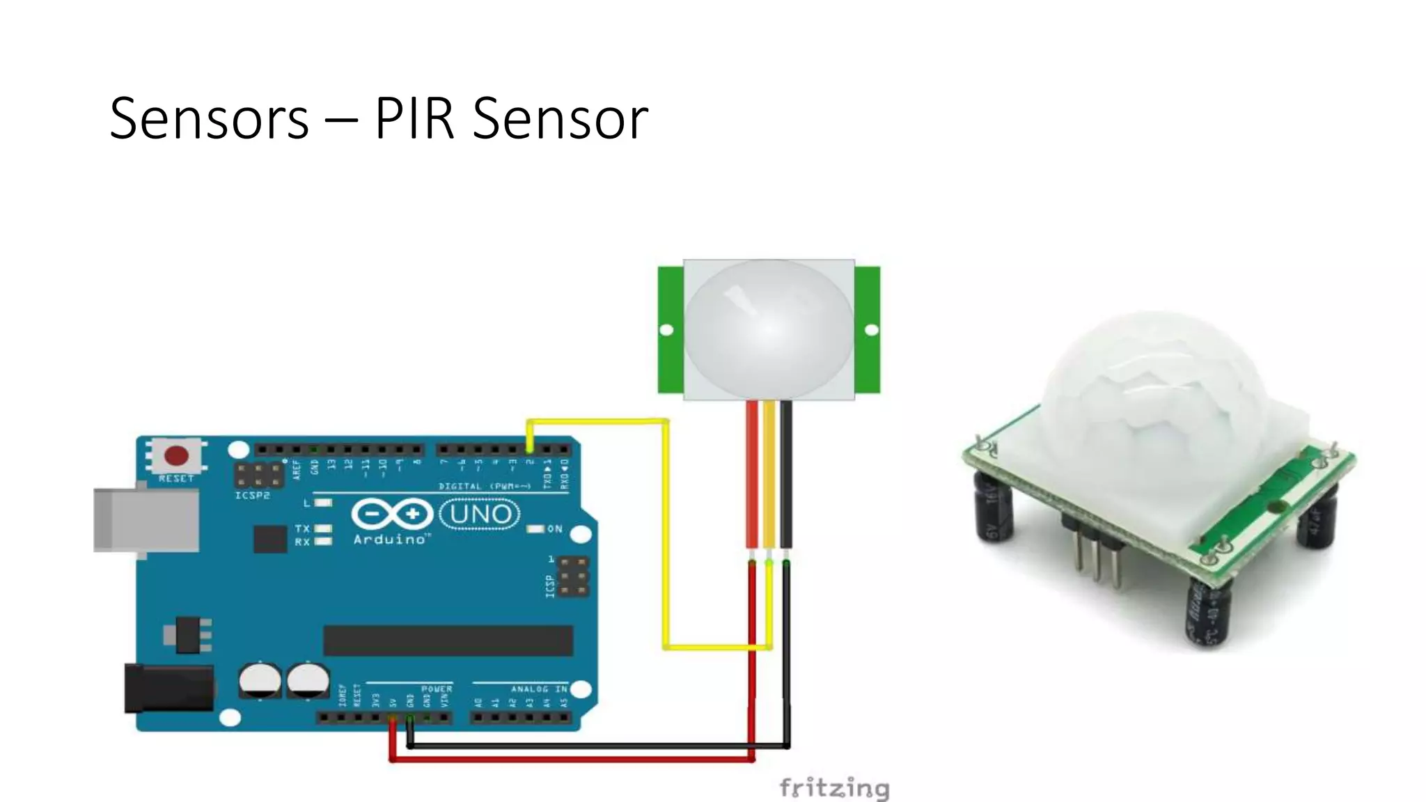
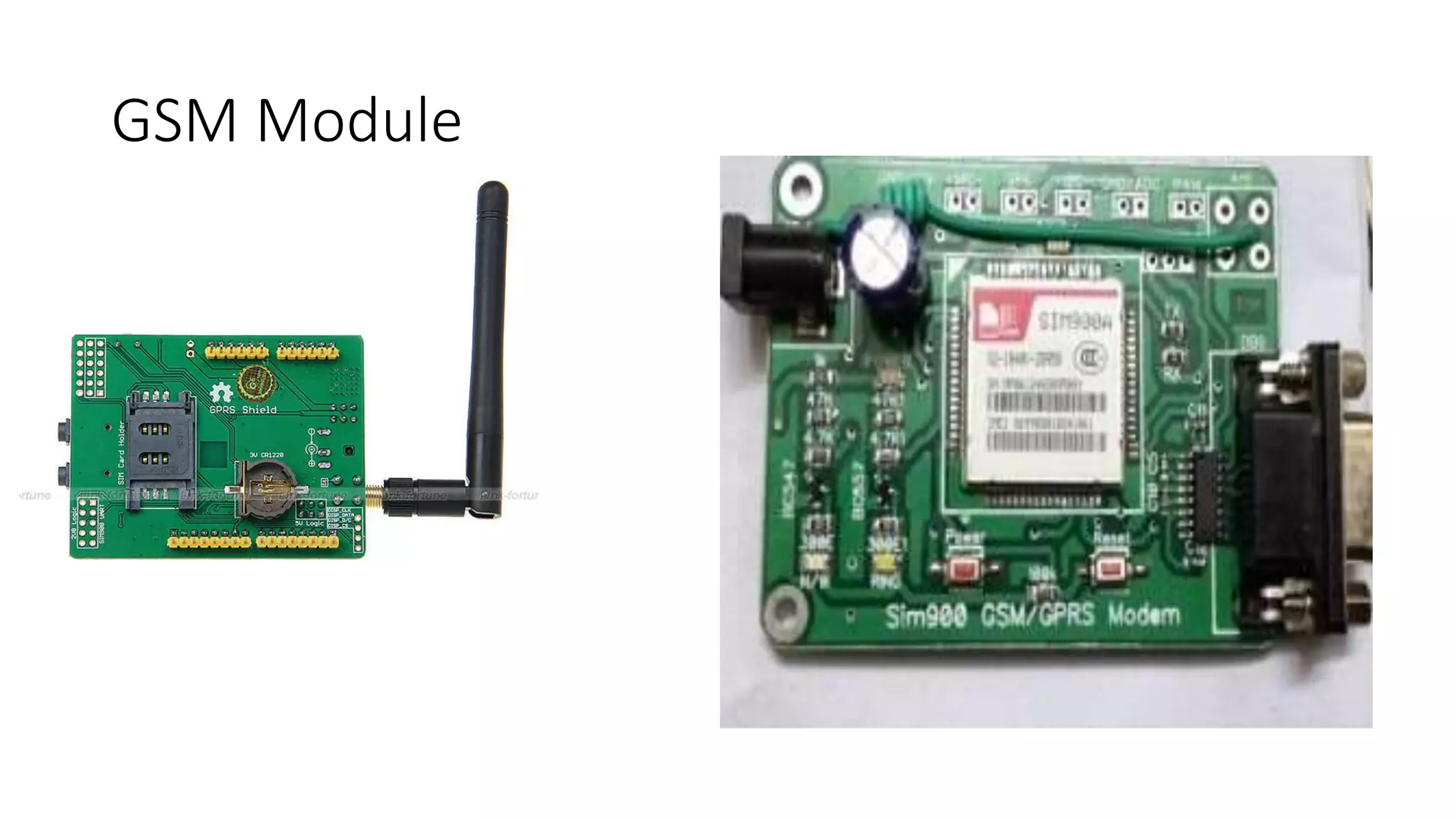
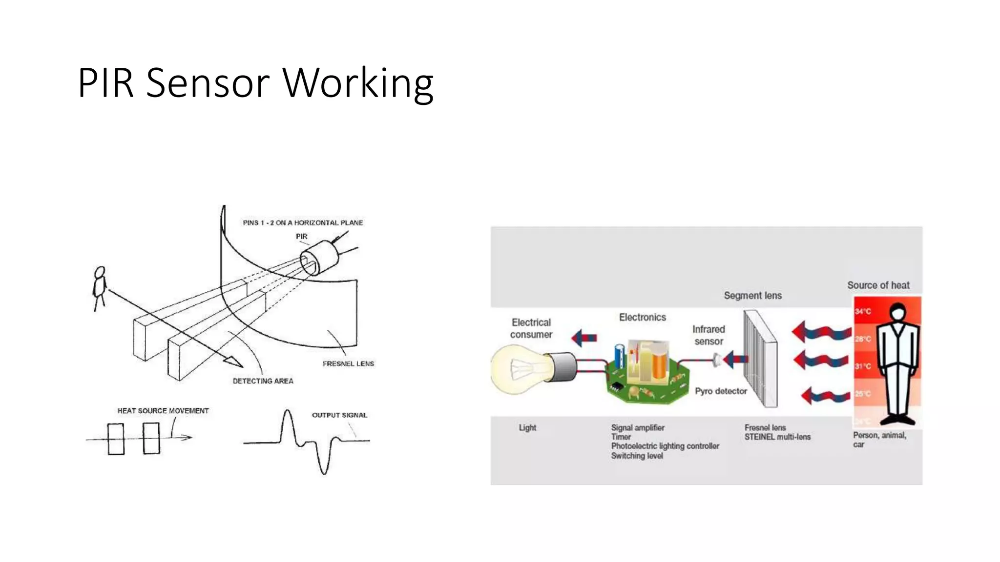
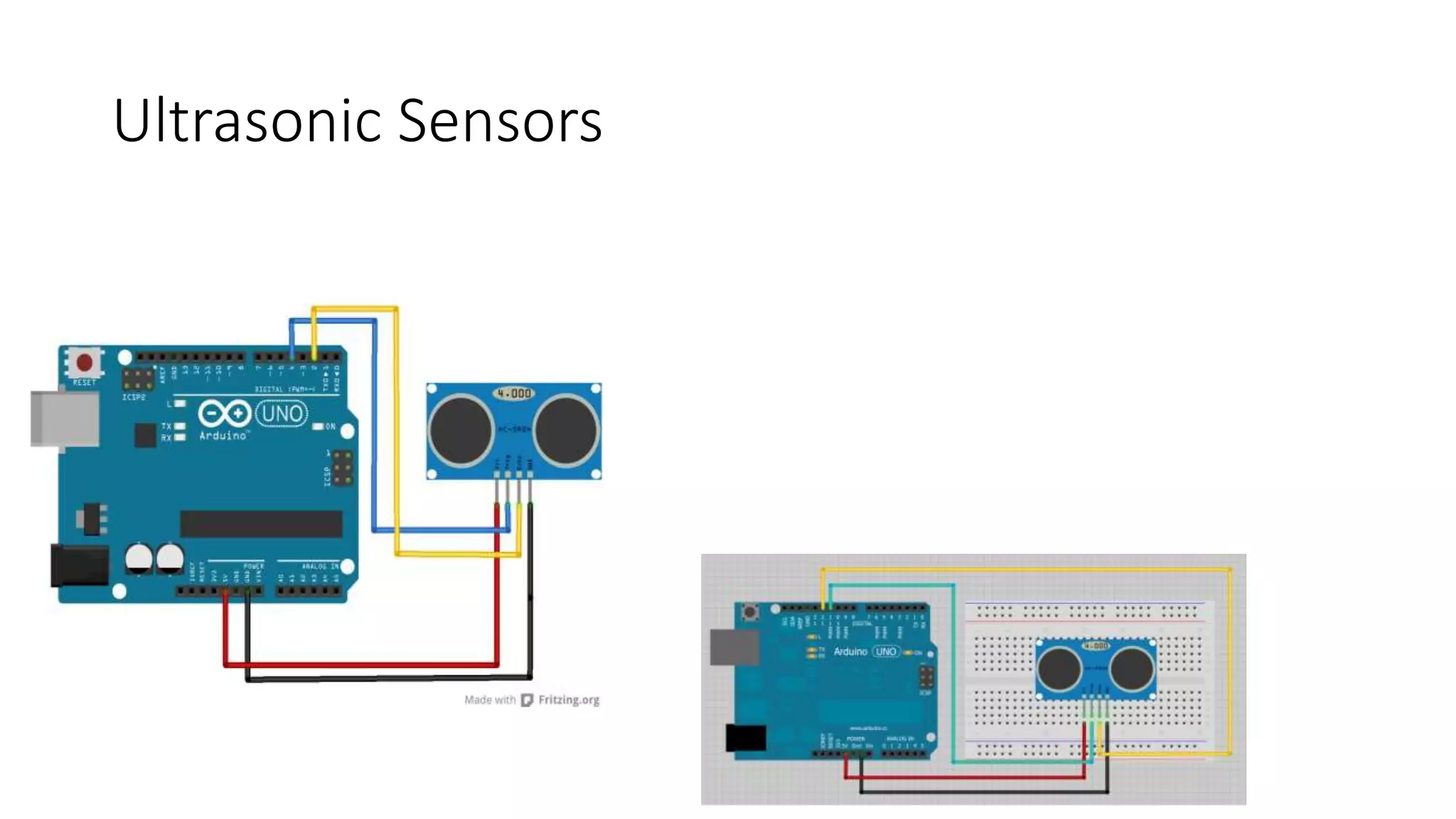
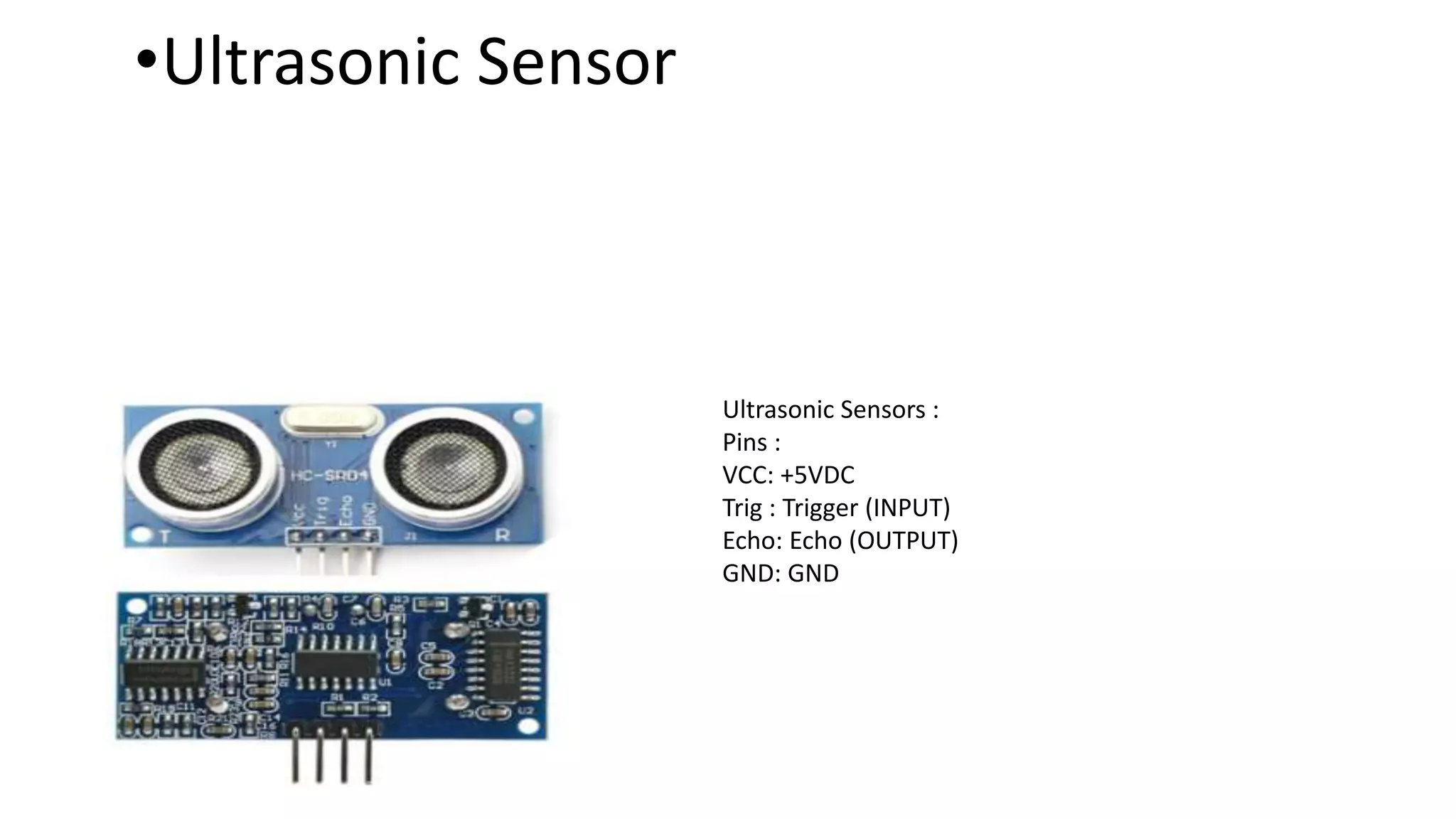
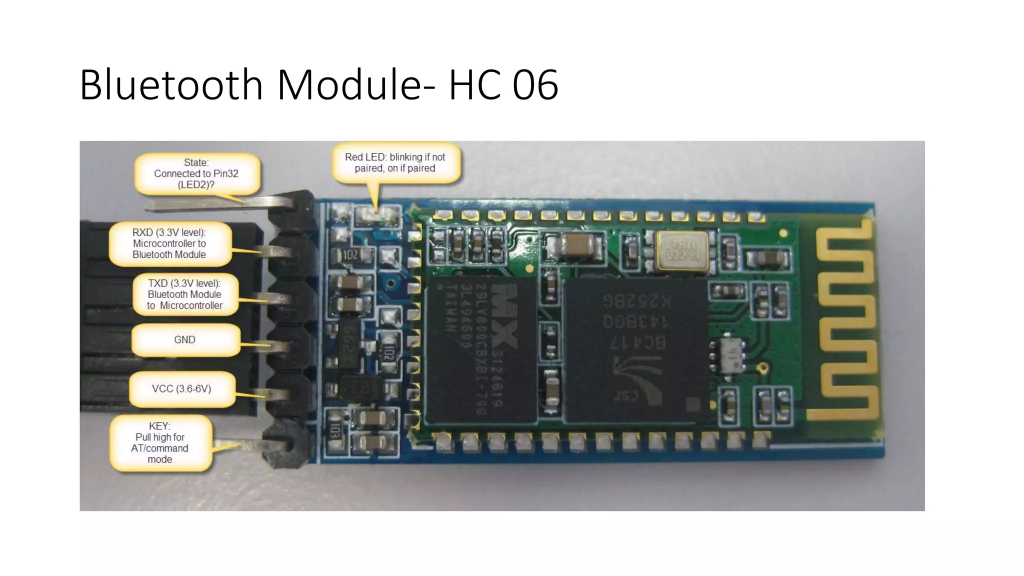
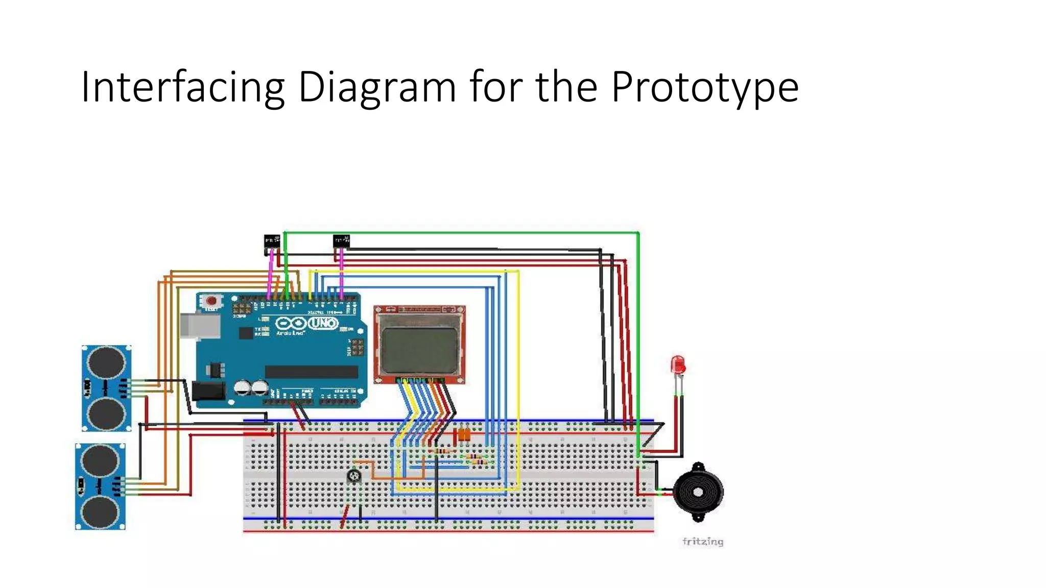
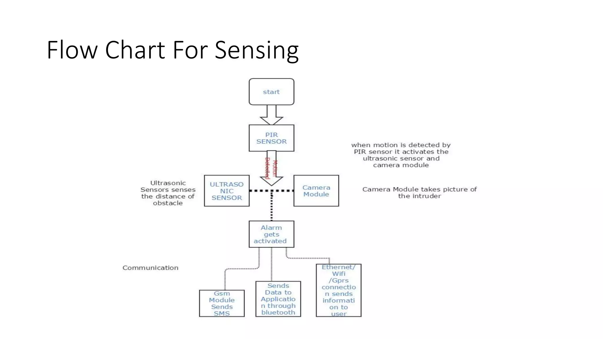
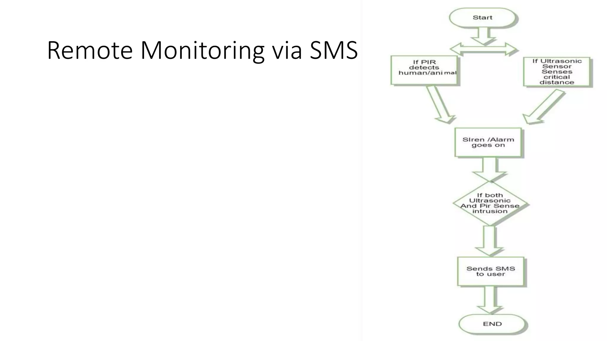
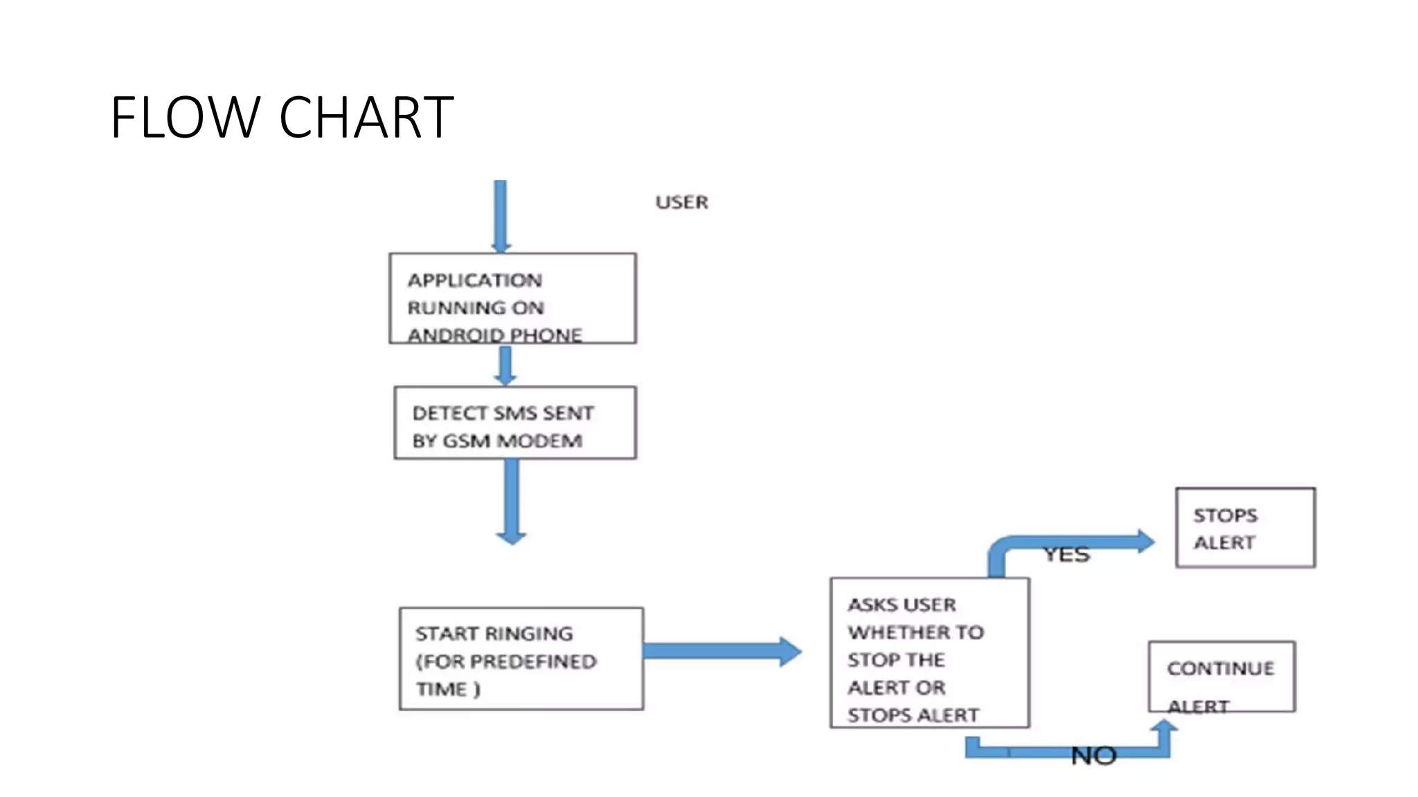
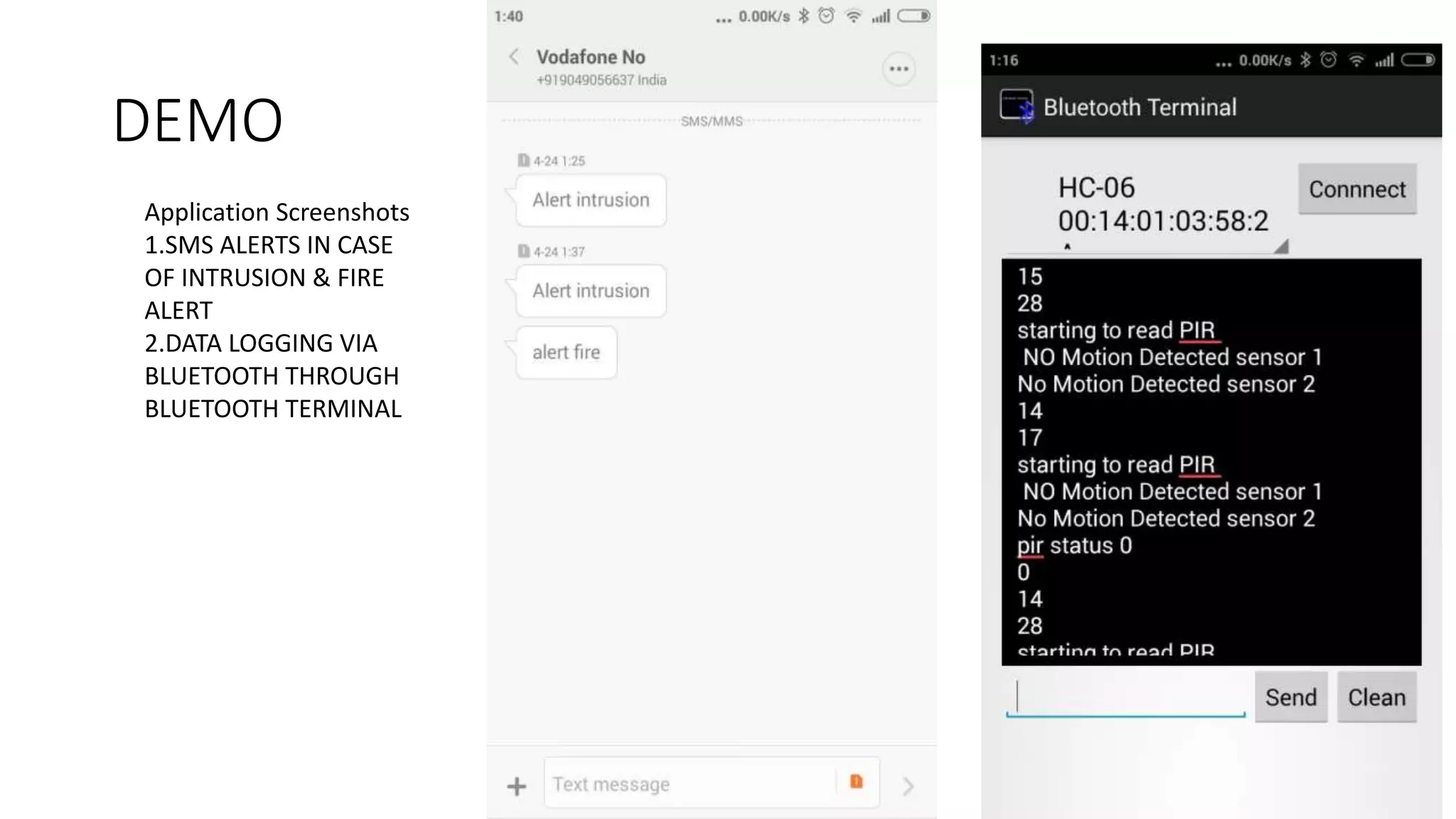
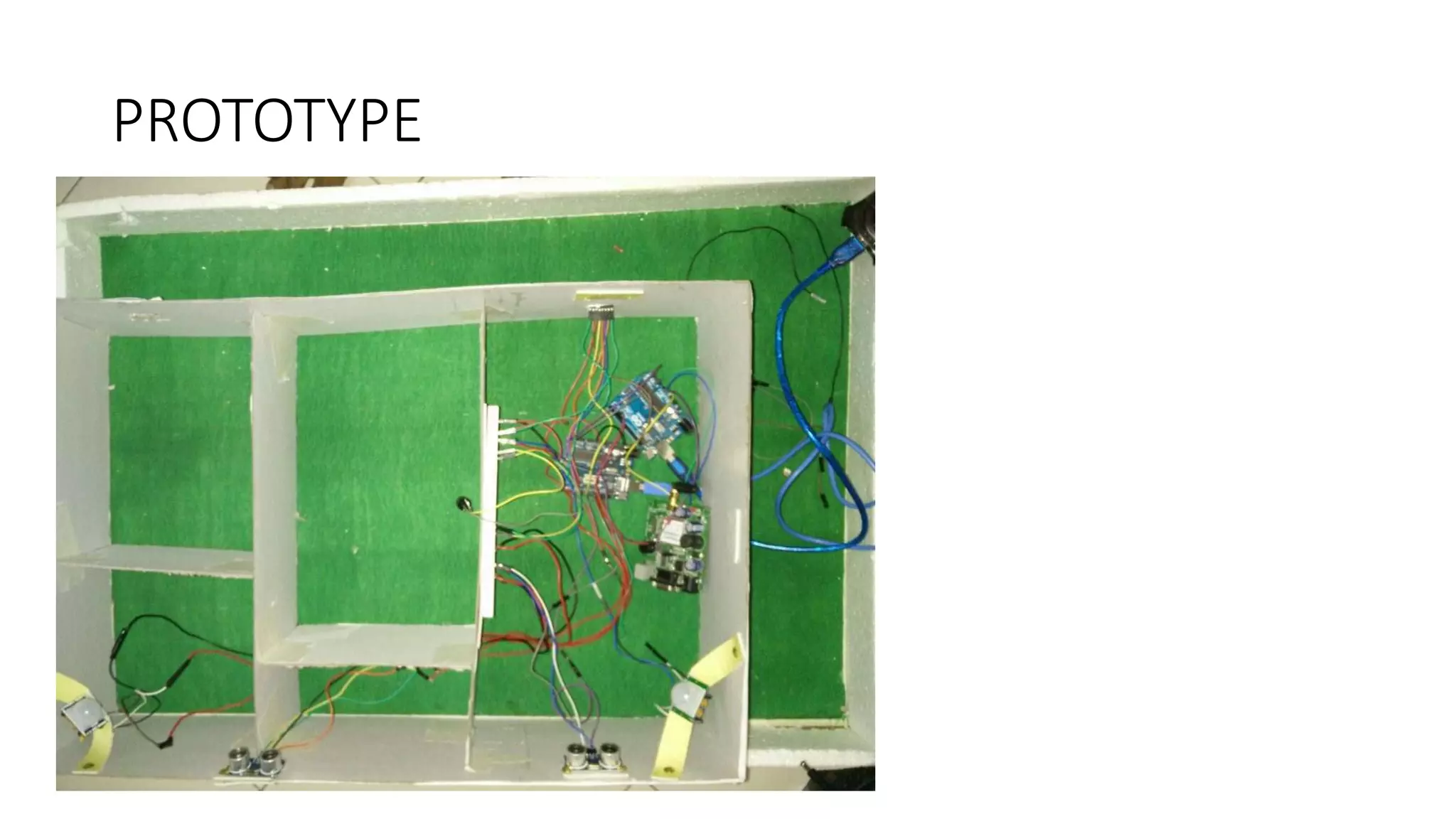
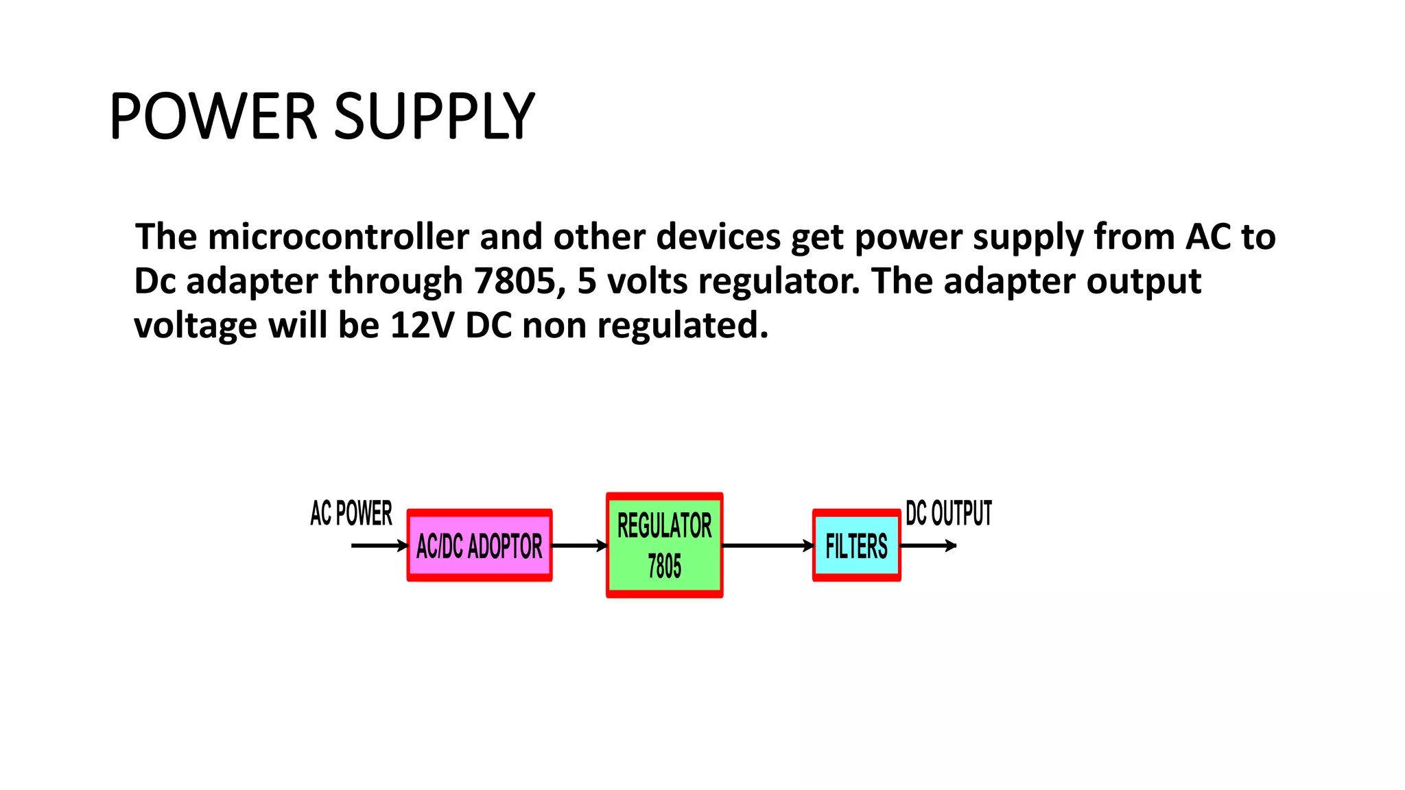
KEMBAR78
Security system using Arduino | PPTX
MIT COLLEGE OF ENGINEERING
PAUD ROAD,PUNE-411038
(2014-2015)
DEPARTMENT OF
ELECTRONICS AND TELECOMMUNICATION ENGINEERING
MINI PROJECT ON
Arduino Based Intrusion Alert System For Security Purpose
BY
Apoorw Anand (3123006)
CONTENTS
• Objective
• Introduction
• Block Diagram
• Components & Interfacing Diagrams
• Working Principle
• Advantages
• Applications
• Limitations
• Future Scope of Work
• Conclusion
OBJECTIVE
The objective of this project is to design and develop a wireless
communication link to monitor our organizations that require high
security like Banks , Offices etc.
Introduction
• Safety and security of any living or working place is one of the most
primary concerns. Today’s security systems include CCTV surveillance
which are very costly and many of these systems do not trigger any
alarm if intrusion or fire is detected. Thus a cost-effective and fast-
reactive security system is needed.
• For this purpose we have made a prototype of such system which
consists of two sensors- PIR sensor and Ultrasonic sensor; a
microcontroller unit- Arduino Uno board and a SIM900 GSM module.
• If there is intrusion through any of these access points, then the
sensor will detect it, generate pulses to be read by Arduino and then
the procedure similar to that of PIR sensor is followed.
Block Diagram
Sensing
Block Diagram(cont.)
Information Processing
BLOCK DIAGRAM
Components
• Arduino Microcontroller.
• Ultrasonic Sensor.
• PIR Sensor.
• LCD Display.
• LED and Buzzer/Alarm.
• GSM and Bluetooth Module
Arduino Board
Sensors – PIR Sensor
GSM Module
PIR Sensor Working
Ultrasonic Sensors
•Ultrasonic Sensor
Ultrasonic Sensors :
Pins :
VCC: +5VDC
Trig : Trigger (INPUT)
Echo: Echo (OUTPUT)
GND: GND
Piezoelectric Buzzer
Bluetooth Module- HC 06
Interfacing Diagram for the Prototype
Flow Chart For Sensing
Remote Monitoring via SMS
FLOW CHART
DEMO
Application Screenshots
1.SMS ALERTS IN CASE
OF INTRUSION & FIRE
ALERT
2.DATA LOGGING VIA
BLUETOOTH THROUGH
BLUETOOTH TERMINAL
PROTOTYPE
PROTOTYPE
POWER SUPPLY
The microcontroller and other devices get power supply from AC to
Dc adapter through 7805, 5 volts regulator. The adapter output
voltage will be 12V DC non regulated.
AC/DCADOPTOR
REGULATOR
7805
FILTERS
ACPOWER DCOUTPUT
GSM MODEM
• GSM Modem is a multi-functional, ready to use,
rugged unit that can be embedded or plugged into
any application.
• The Modem can be controlled and customized to
various levels by using the standard AT commands.
GSM MODEM(CONT…)
The modem comprises several interfaces:-
• LED Function including operating Status
• External antenna
• Serial and control link
• Power Supply
• SIM card holder
Gsm (cont.)
• The GSM module is connected with the microcontroller through serial
port. Using ‘AT’ commands the SMS is transferred to the GSM
module. The GSM module converts the digital information into
airborne signals. Through GSM network the SMS is transferred to the
required person’s hand phone.
• This system offers better solution for the Bank security system and
also it will help you to track the intruder.
Remote Monitoring via Bluetooth Module
• Screenshot for the open source application for sending serial data to
android over Bluetooth.
• Bluetooth Module connected to Rx & Tx Pins of Arduino Sends data to
Paired android Phone .
• User can read the real time log in the serial monitor and also turn off
the alarm from his/her mobile just by sending command.
• Demonstration for the working of application done through the video
provided in zip file.
I2C
• The START condition acts as a signal to all connected IC's that
something is about to be transmitted on the bus.
• A STOP condition is sent. This is the signal for all devices on the bus
that the bus is available again (idle).
I2C TOPOLOGY
ADVANTAGES
• The status of various devices can be monitored and controlled from
anywhere.
• The operation of the system is very simple and can be used by
anyone with a basic knowledge of operating mobile phones.
• Easy to upgrade as per the user requirement.
APPLICATIONS
• Home Automation & Security
• Office Automation & Industrial Automation
• To control water pump sets in agricultural fields.
• The security system can be employed in household
or any organization.
LIMITATIONS
• If the main module or the handset is not in the cellular range ,we can’t
control the devices.
• The sensors use RF transmitter and receiver which has limited range, hence
sensors have to be in close vicinity of the main module
FUTURE SCOPE OF WORK
• It can be used for high security in banks and other
organizations.
• Connecting More Devices.
• Provision To Store Several Mobile Numbers
• Video Recording Once Alarm Gets Triggered
CONCLUSION
• We presented an approach that can be employed to improve the
performance of various devices that are not in the close vicinity of
the user.
• The user was informed about the action through a reply SMS sent
by the modem at the receiver.

Security system using Arduino

  • 1.
    MIT COLLEGE OFENGINEERING PAUD ROAD,PUNE-411038 (2014-2015) DEPARTMENT OF ELECTRONICS AND TELECOMMUNICATION ENGINEERING MINI PROJECT ON Arduino Based Intrusion Alert System For Security Purpose BY Apoorw Anand (3123006)
  • 2.
    CONTENTS • Objective • Introduction •Block Diagram • Components & Interfacing Diagrams • Working Principle • Advantages • Applications • Limitations • Future Scope of Work • Conclusion
  • 3.
    OBJECTIVE The objective ofthis project is to design and develop a wireless communication link to monitor our organizations that require high security like Banks , Offices etc.
  • 4.
    Introduction • Safety andsecurity of any living or working place is one of the most primary concerns. Today’s security systems include CCTV surveillance which are very costly and many of these systems do not trigger any alarm if intrusion or fire is detected. Thus a cost-effective and fast- reactive security system is needed. • For this purpose we have made a prototype of such system which consists of two sensors- PIR sensor and Ultrasonic sensor; a microcontroller unit- Arduino Uno board and a SIM900 GSM module. • If there is intrusion through any of these access points, then the sensor will detect it, generate pulses to be read by Arduino and then the procedure similar to that of PIR sensor is followed.
  • 5.
  • 6.
  • 7.
  • 8.
    Components • Arduino Microcontroller. •Ultrasonic Sensor. • PIR Sensor. • LCD Display. • LED and Buzzer/Alarm. • GSM and Bluetooth Module
  • 9.
  • 10.
  • 11.
  • 12.
  • 13.
  • 14.
    •Ultrasonic Sensor Ultrasonic Sensors: Pins : VCC: +5VDC Trig : Trigger (INPUT) Echo: Echo (OUTPUT) GND: GND
  • 15.
  • 16.
  • 17.
  • 18.
  • 19.
  • 20.
  • 21.
    DEMO Application Screenshots 1.SMS ALERTSIN CASE OF INTRUSION & FIRE ALERT 2.DATA LOGGING VIA BLUETOOTH THROUGH BLUETOOTH TERMINAL
  • 22.
  • 23.
  • 24.
    POWER SUPPLY The microcontrollerand other devices get power supply from AC to Dc adapter through 7805, 5 volts regulator. The adapter output voltage will be 12V DC non regulated. AC/DCADOPTOR REGULATOR 7805 FILTERS ACPOWER DCOUTPUT
  • 25.
    GSM MODEM • GSMModem is a multi-functional, ready to use, rugged unit that can be embedded or plugged into any application. • The Modem can be controlled and customized to various levels by using the standard AT commands.
  • 26.
    GSM MODEM(CONT…) The modemcomprises several interfaces:- • LED Function including operating Status • External antenna • Serial and control link • Power Supply • SIM card holder
  • 27.
    Gsm (cont.) • TheGSM module is connected with the microcontroller through serial port. Using ‘AT’ commands the SMS is transferred to the GSM module. The GSM module converts the digital information into airborne signals. Through GSM network the SMS is transferred to the required person’s hand phone. • This system offers better solution for the Bank security system and also it will help you to track the intruder.
  • 28.
    Remote Monitoring viaBluetooth Module • Screenshot for the open source application for sending serial data to android over Bluetooth. • Bluetooth Module connected to Rx & Tx Pins of Arduino Sends data to Paired android Phone . • User can read the real time log in the serial monitor and also turn off the alarm from his/her mobile just by sending command. • Demonstration for the working of application done through the video provided in zip file.
  • 29.
    I2C • The STARTcondition acts as a signal to all connected IC's that something is about to be transmitted on the bus. • A STOP condition is sent. This is the signal for all devices on the bus that the bus is available again (idle).
  • 30.
  • 31.
    ADVANTAGES • The statusof various devices can be monitored and controlled from anywhere. • The operation of the system is very simple and can be used by anyone with a basic knowledge of operating mobile phones. • Easy to upgrade as per the user requirement.
  • 32.
    APPLICATIONS • Home Automation& Security • Office Automation & Industrial Automation • To control water pump sets in agricultural fields. • The security system can be employed in household or any organization.
  • 33.
    LIMITATIONS • If themain module or the handset is not in the cellular range ,we can’t control the devices. • The sensors use RF transmitter and receiver which has limited range, hence sensors have to be in close vicinity of the main module
  • 34.
    FUTURE SCOPE OFWORK • It can be used for high security in banks and other organizations. • Connecting More Devices. • Provision To Store Several Mobile Numbers • Video Recording Once Alarm Gets Triggered
  • 35.
    CONCLUSION • We presentedan approach that can be employed to improve the performance of various devices that are not in the close vicinity of the user. • The user was informed about the action through a reply SMS sent by the modem at the receiver.