Downloaded 64 times

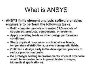
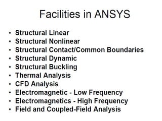


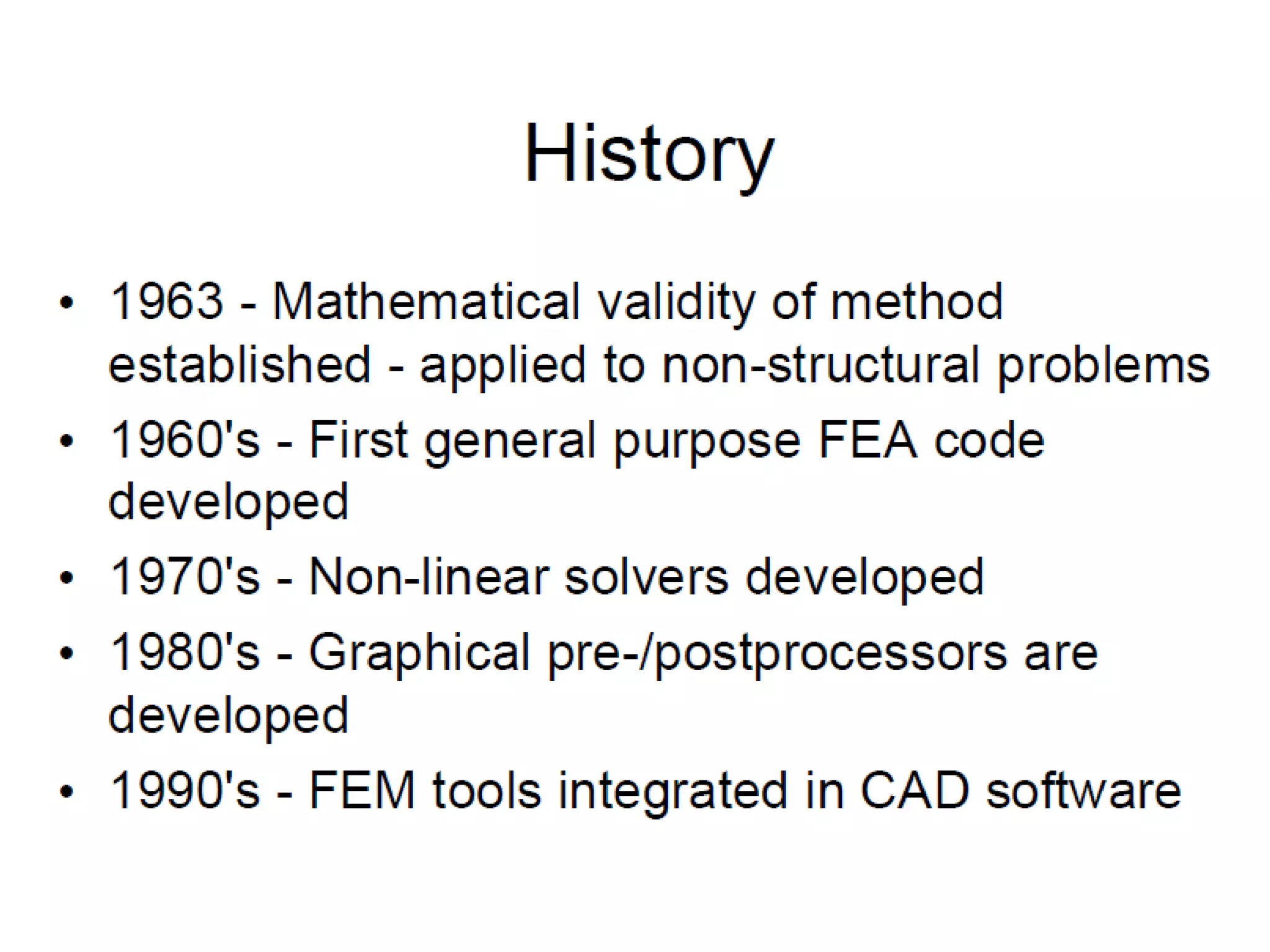

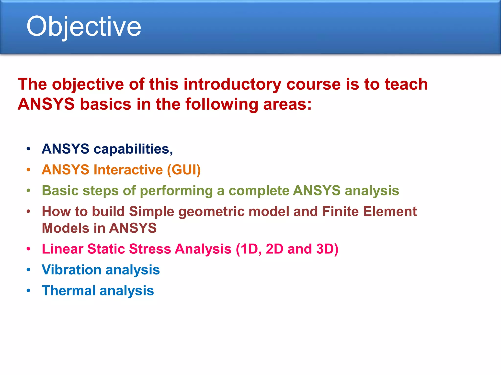
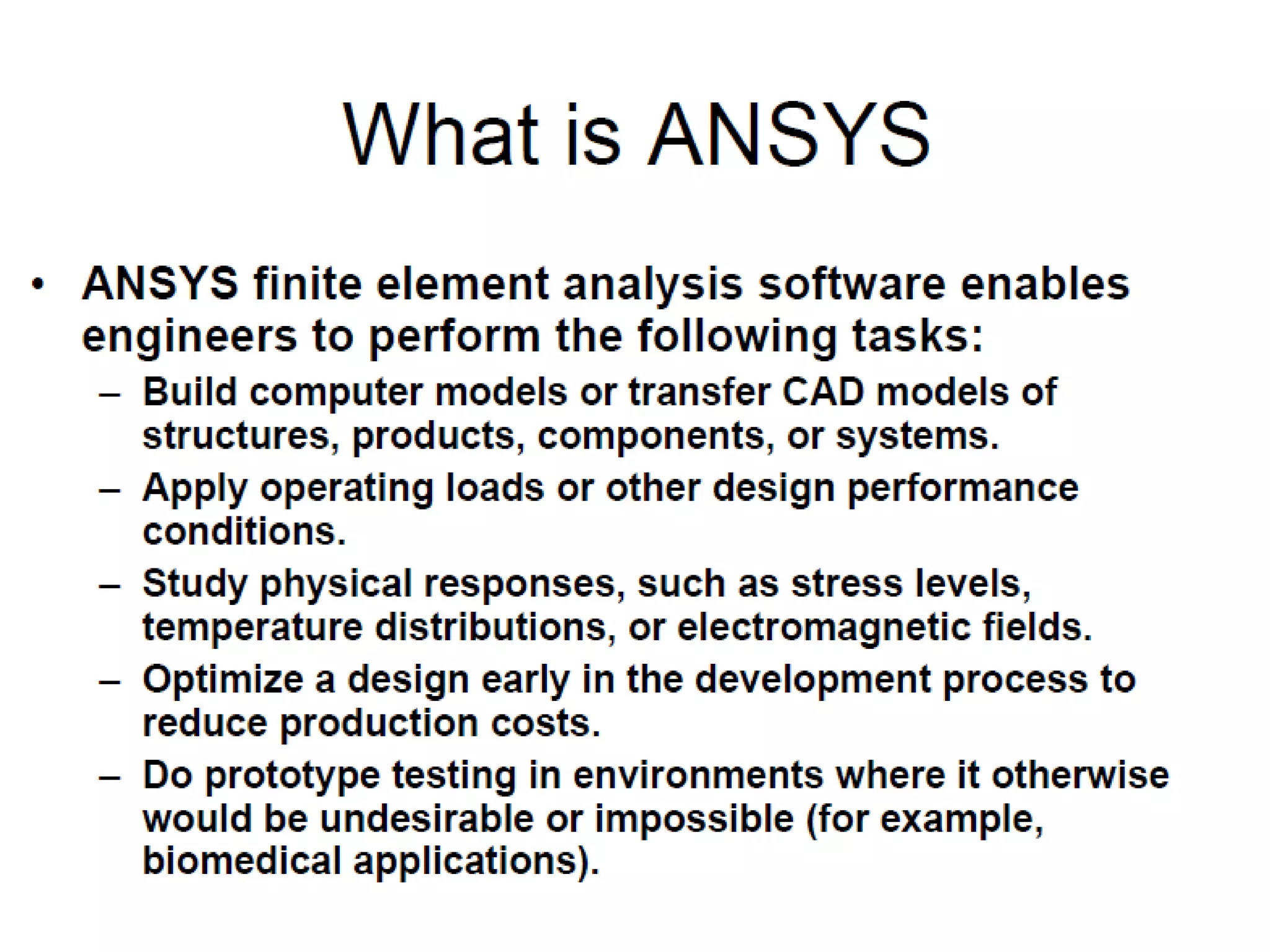
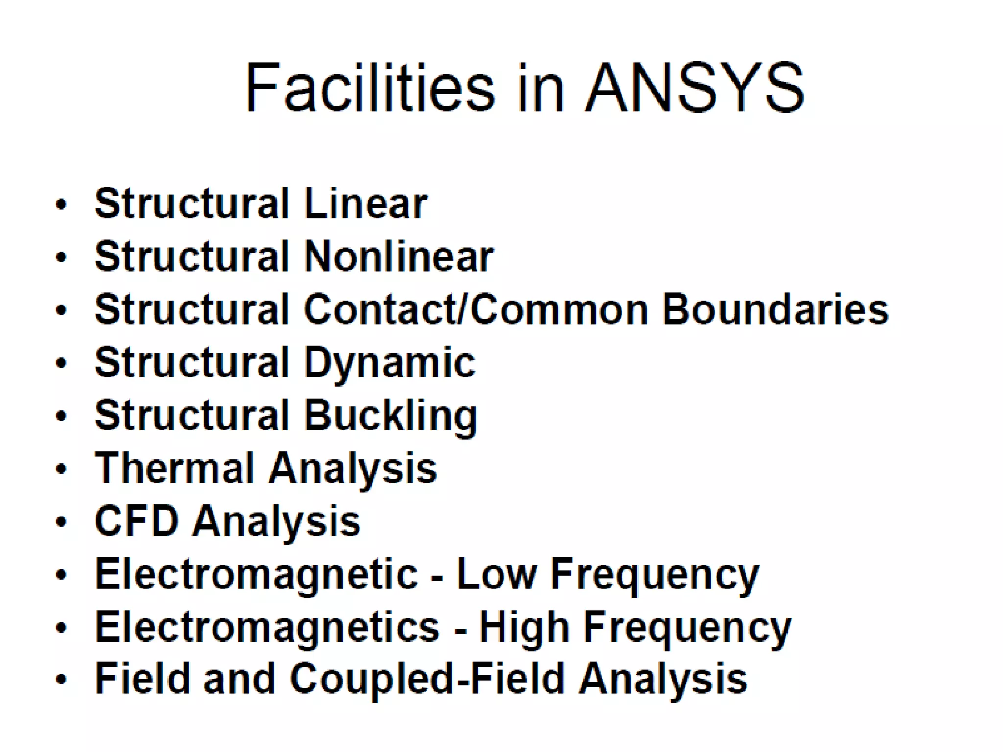


The document discusses Anthropic's Simulation and ANSYS software capabilities. It introduces ANSYS, describing its capabilities for linear static stress analysis, vibration analysis, and thermal analysis. It outlines the basic steps for performing a complete ANSYS analysis, including preprocessing tasks like geometric modeling, applying loads and boundary conditions, element selection, and material property definition before solving and viewing results.
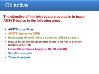
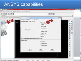
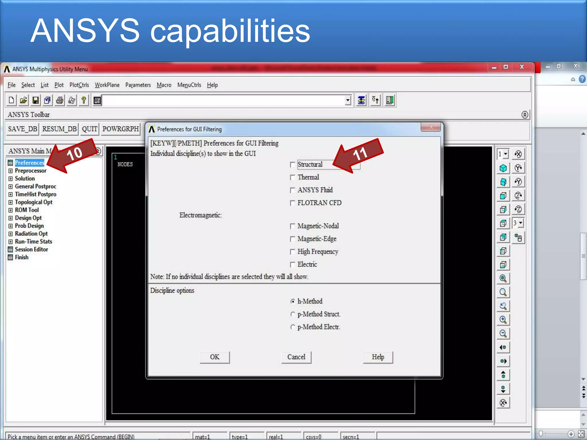
Overview of the ANSYS software course objectives, introducing capabilities, and analysis types.
Overview of the ANSYS software course objectives, introducing capabilities, and analysis types.
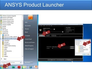
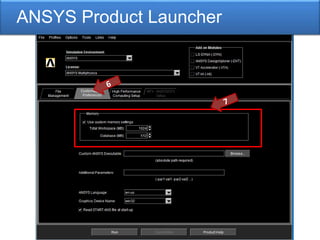
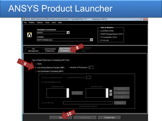
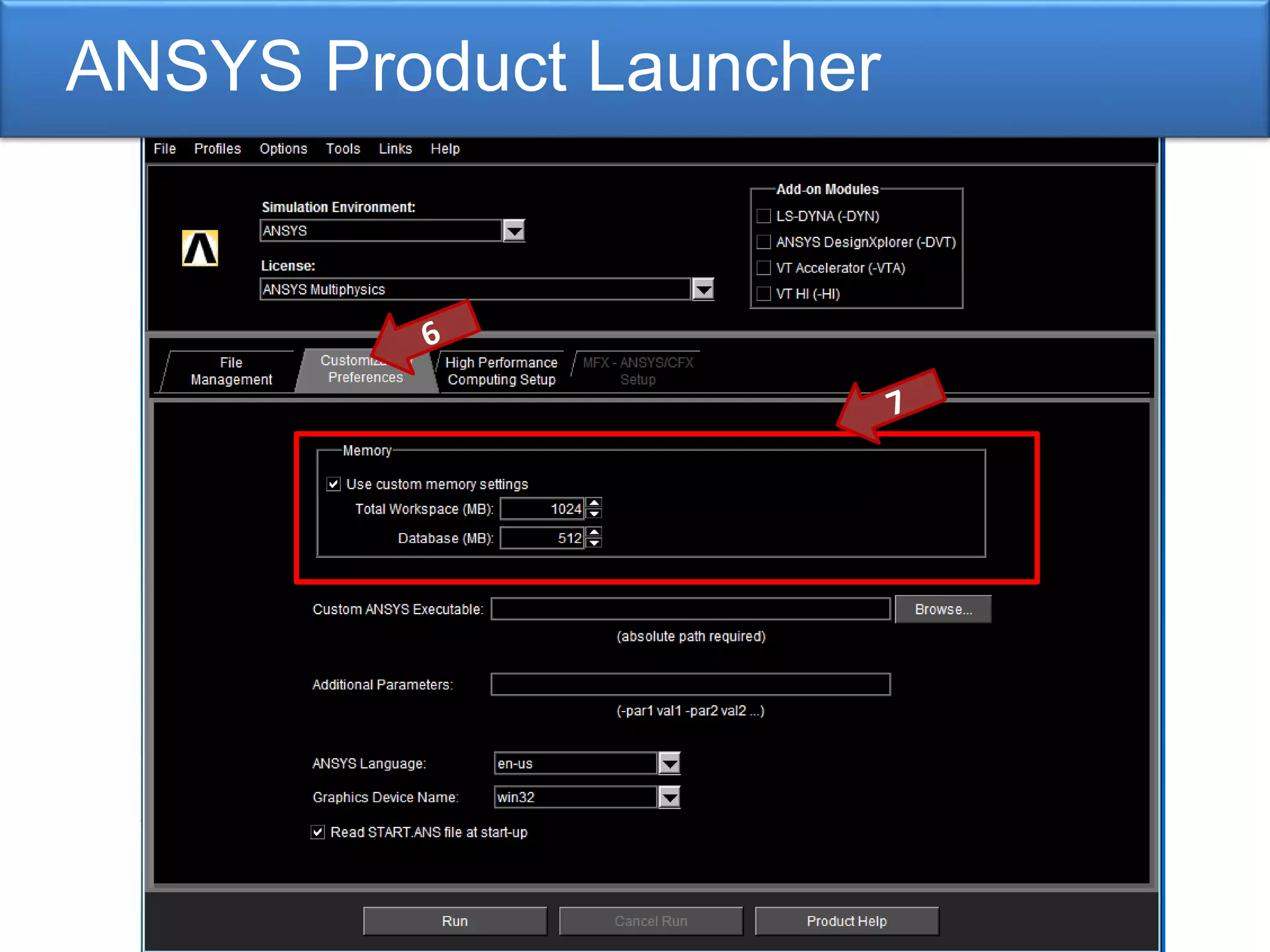
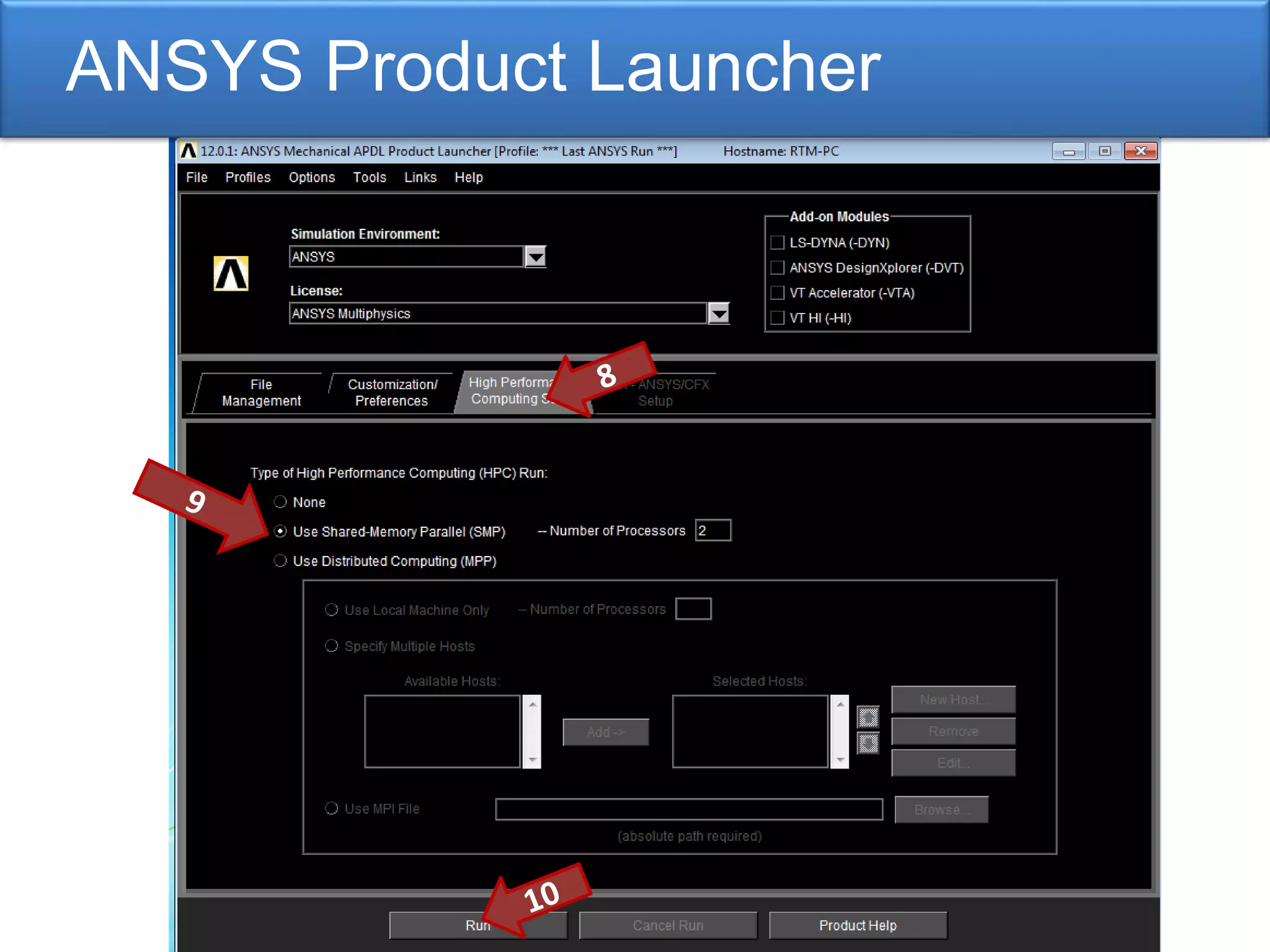
Introduction to the ANSYS Product Launcher, important for accessing various modules within ANSYS.
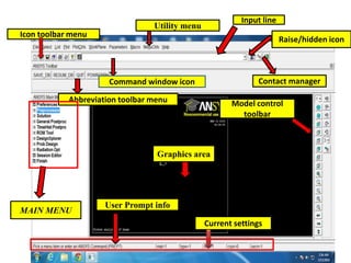
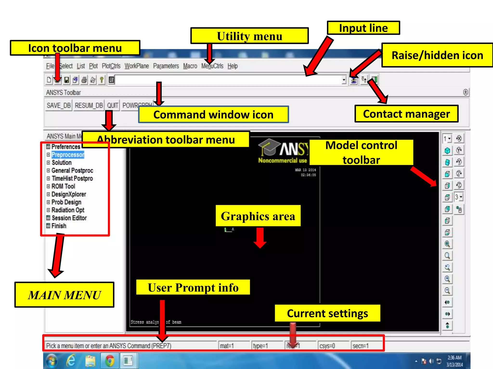
Overview of the ANSYS workspace, including settings, graphics area, and menu options.
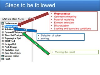
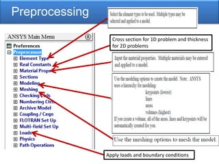
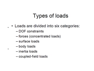
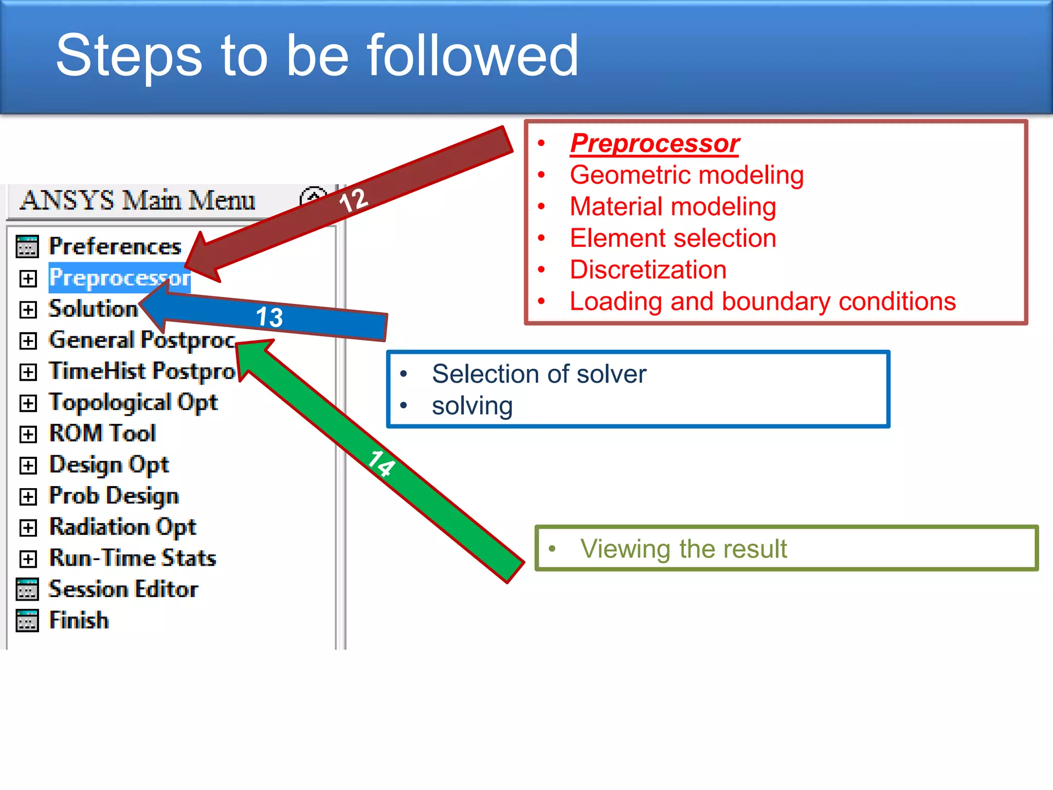
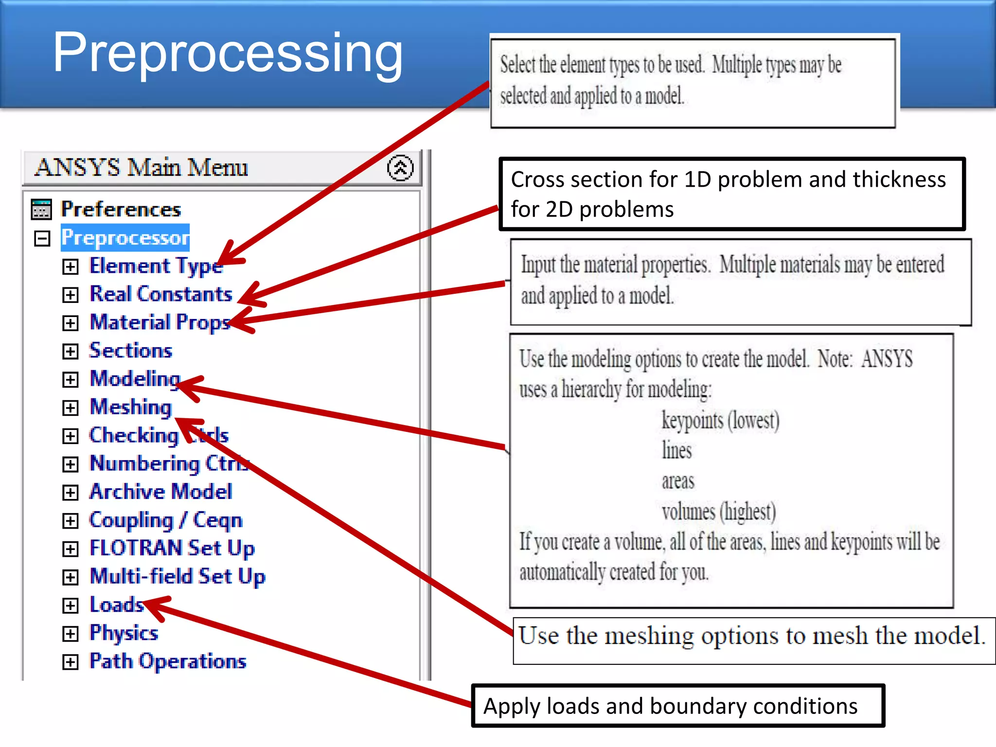
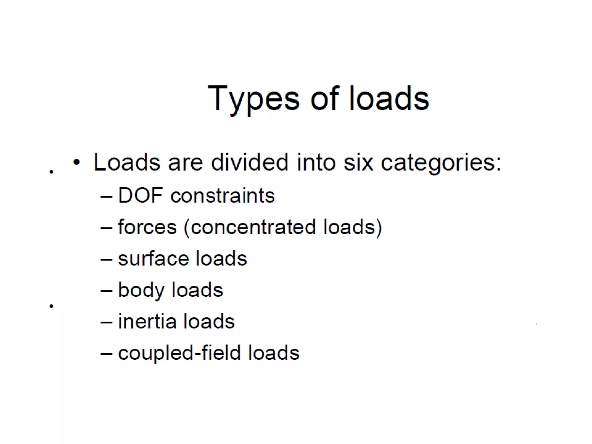
Key steps in performing ANSYS analyses including preprocessing, loads, boundary conditions.
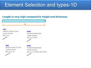
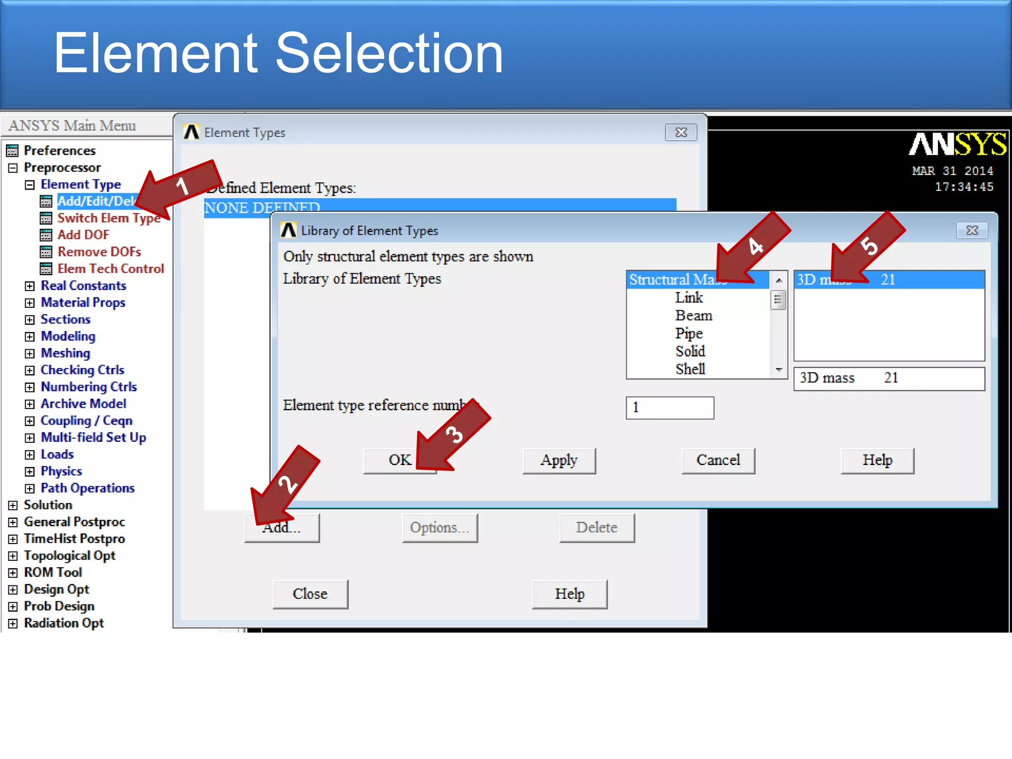
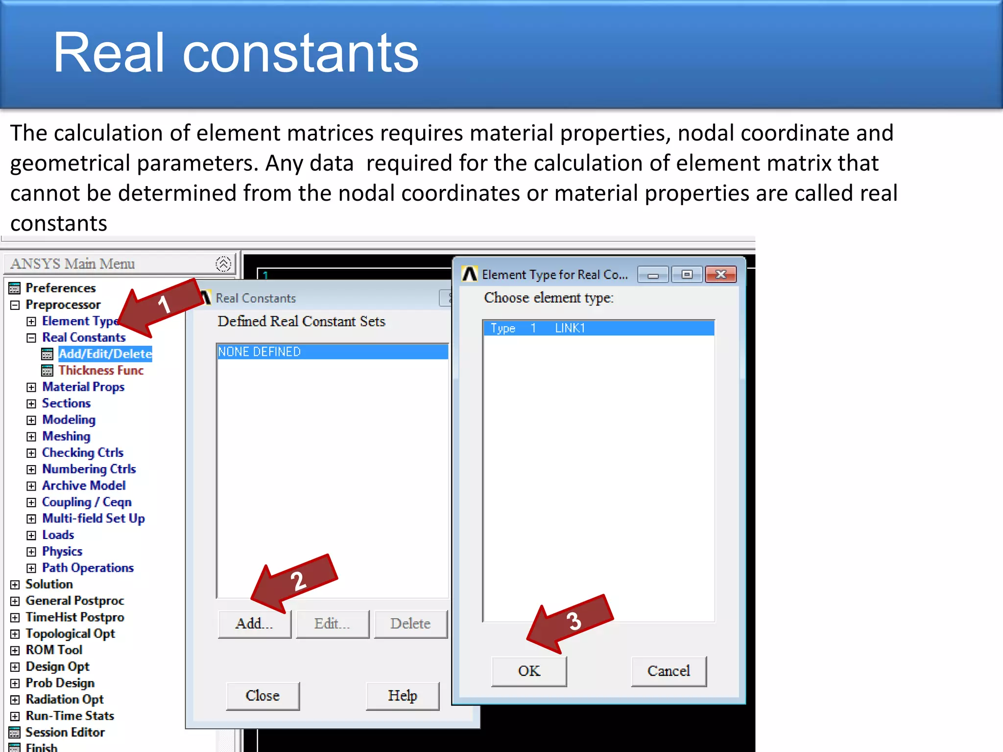
Discusses the selection of elements and the definition of real constants necessary for calculations.
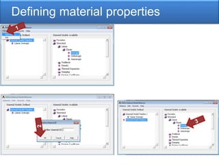
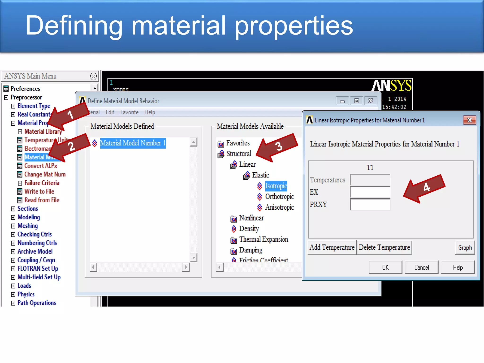
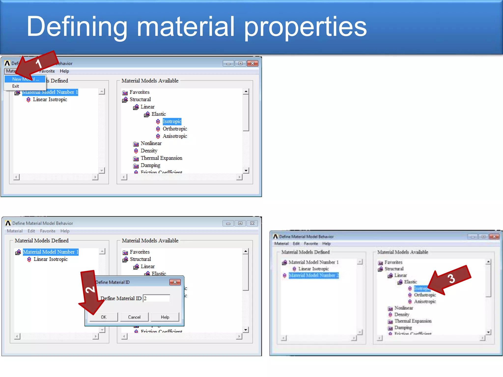
Importance of defining material properties within ANSYS for accurate modeling and analysis.
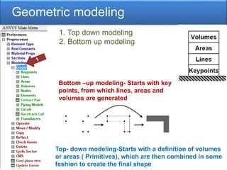
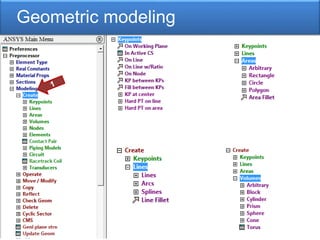
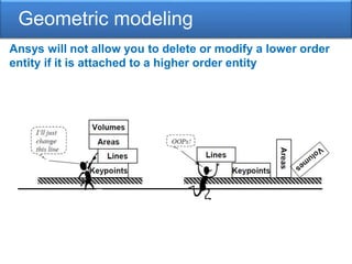
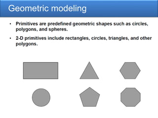
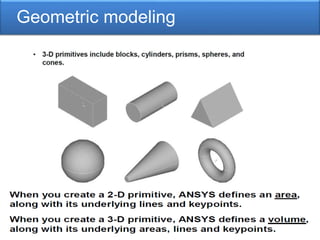
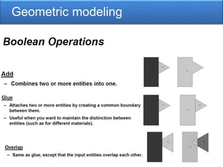
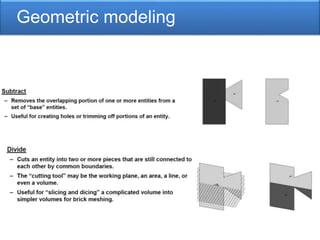
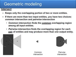
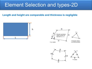
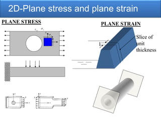
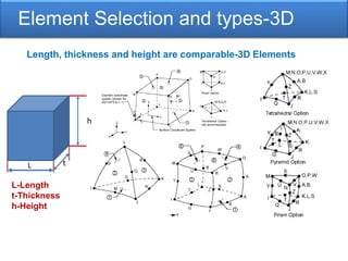
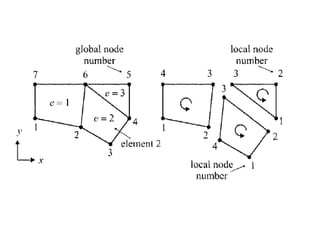
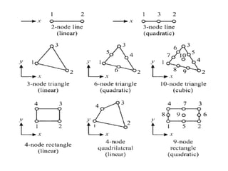
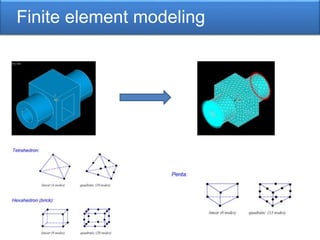
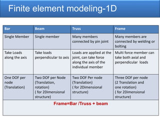
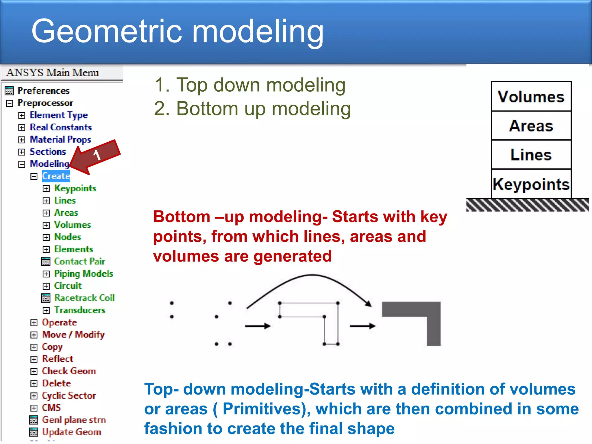
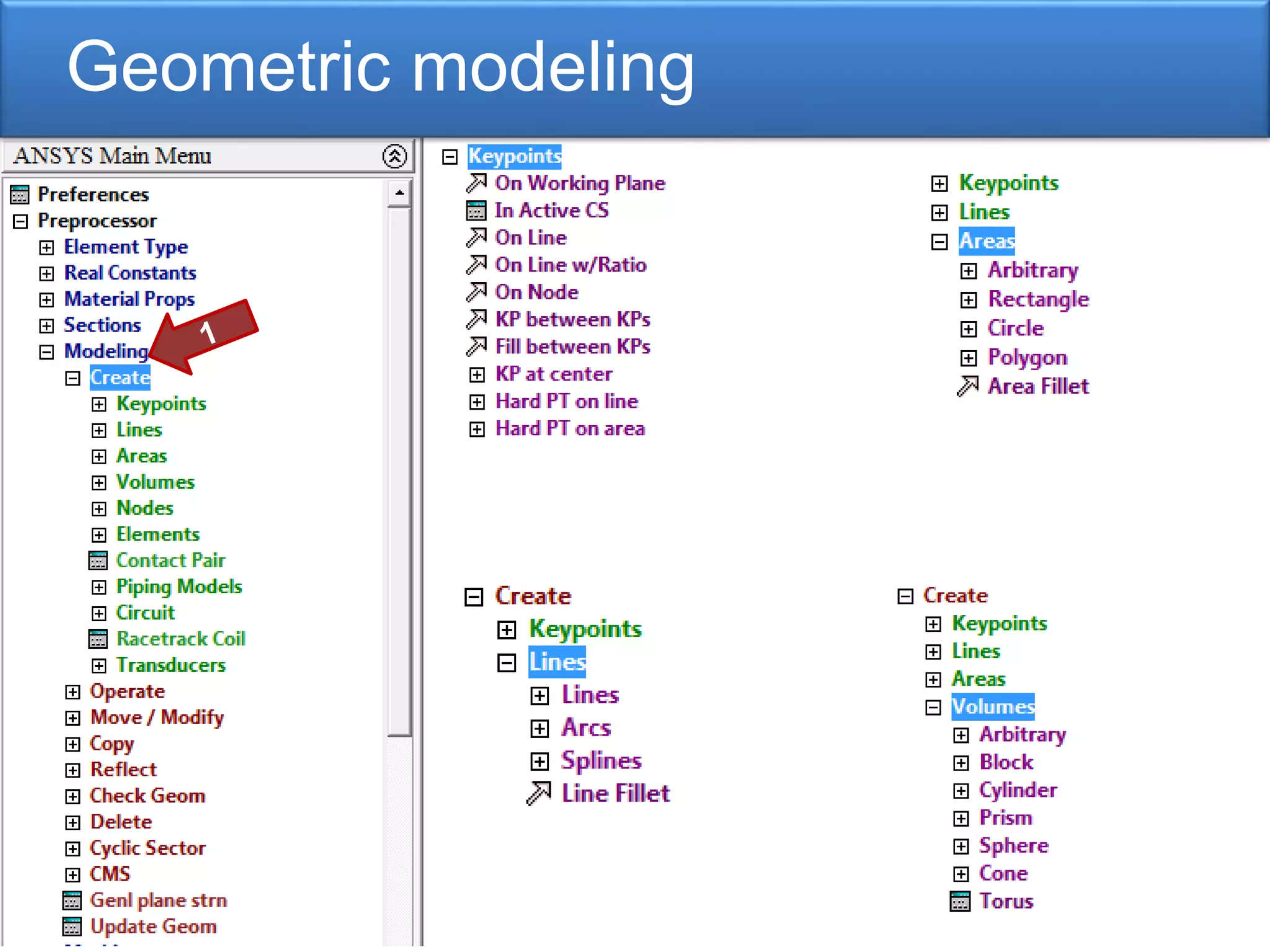
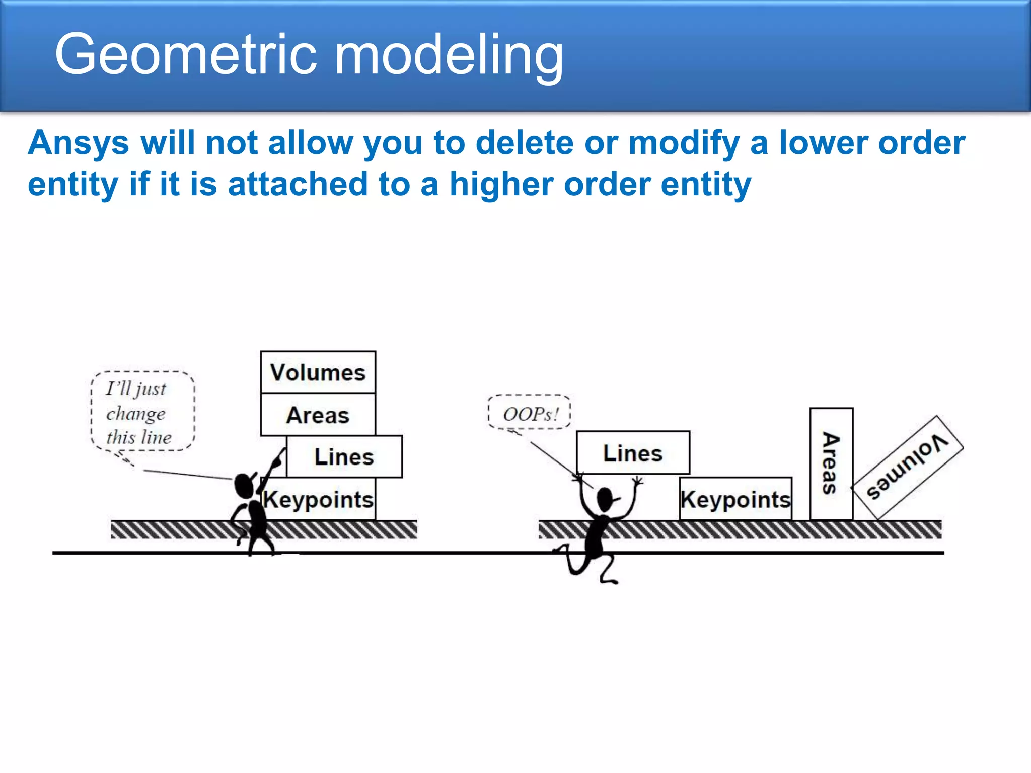
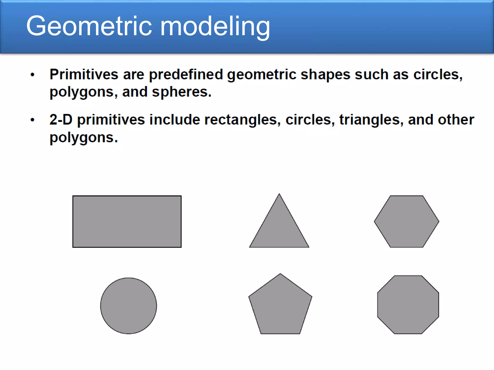
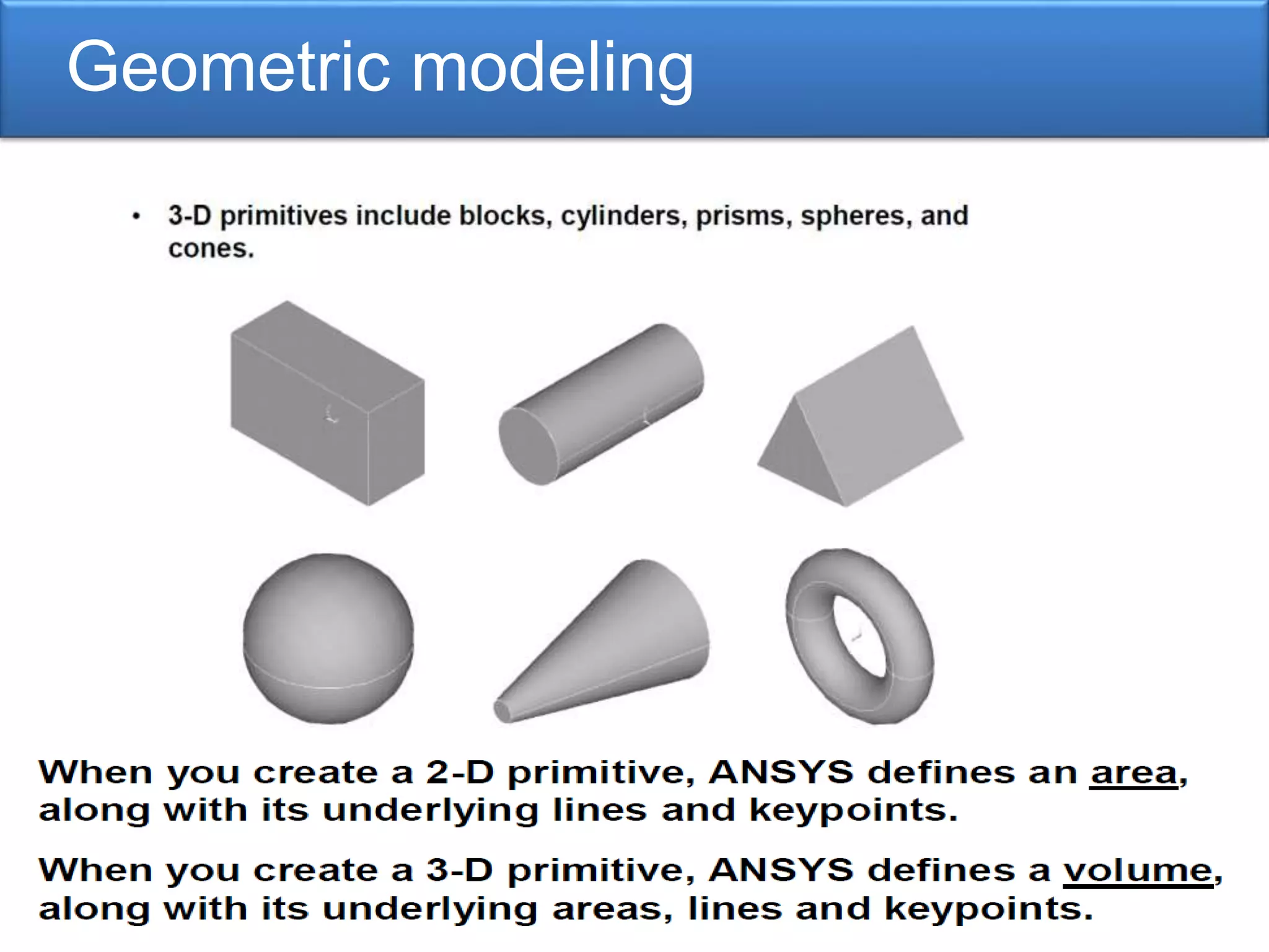
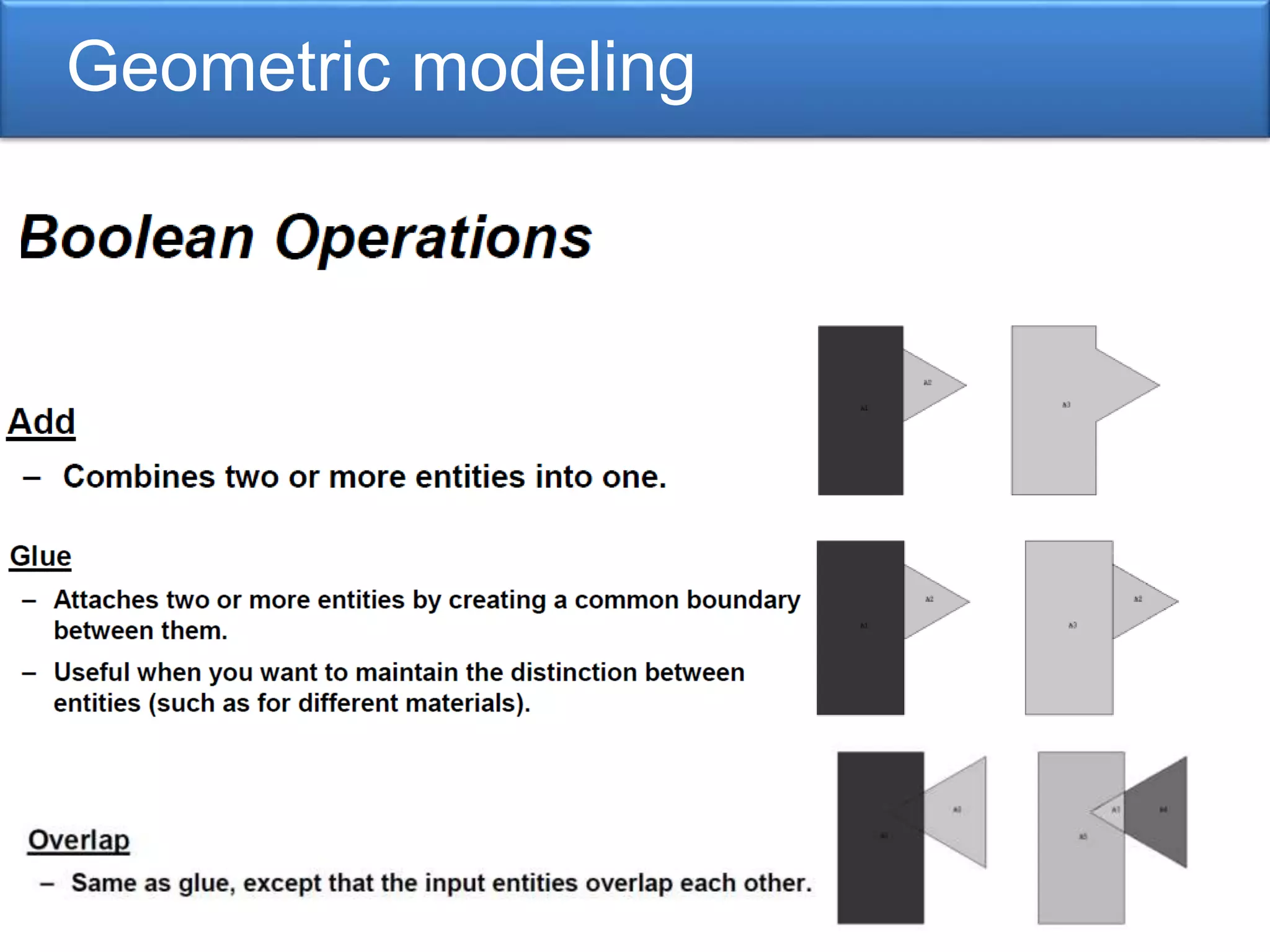
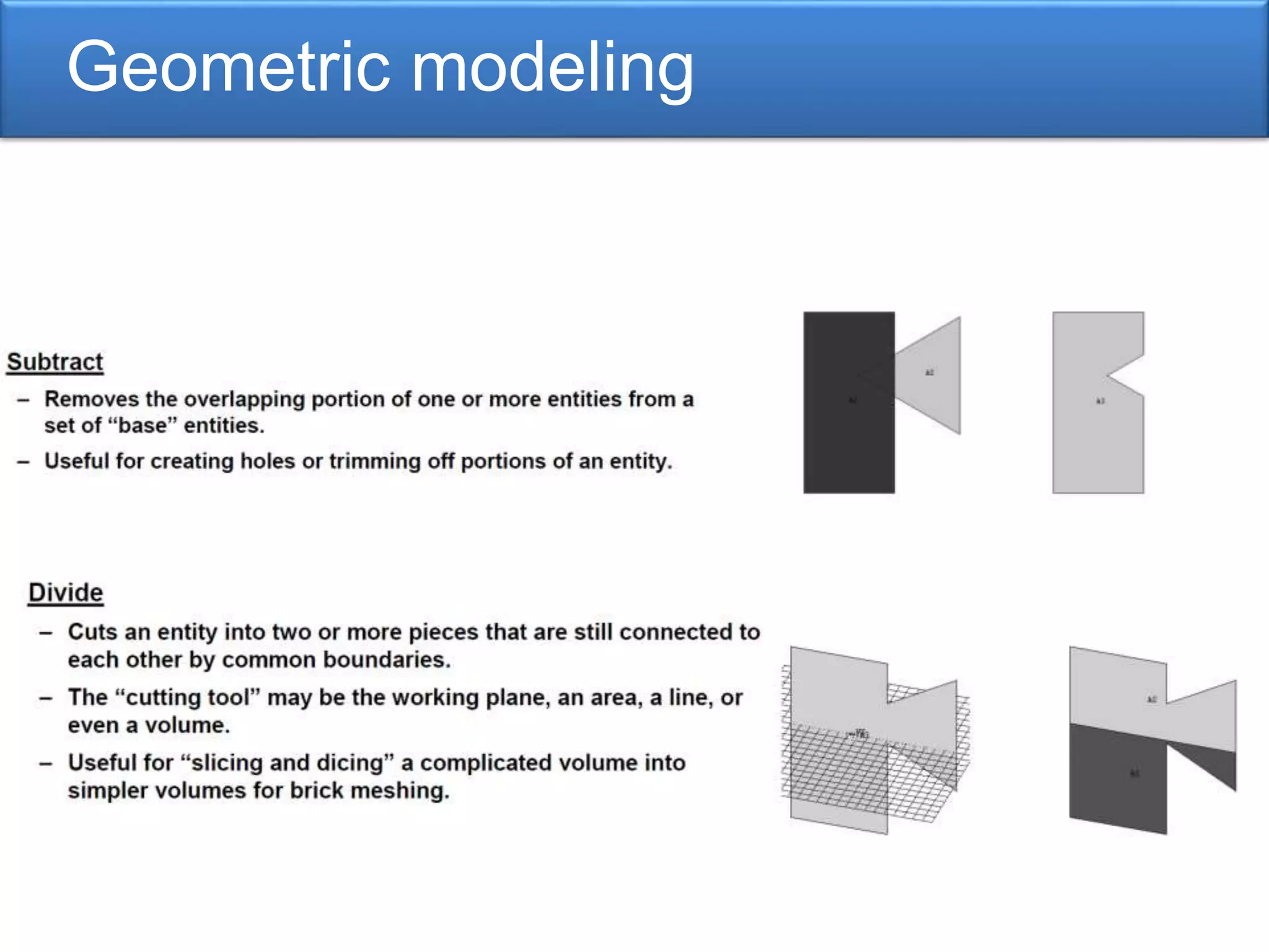
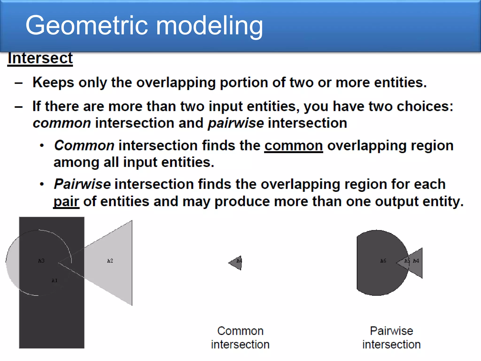
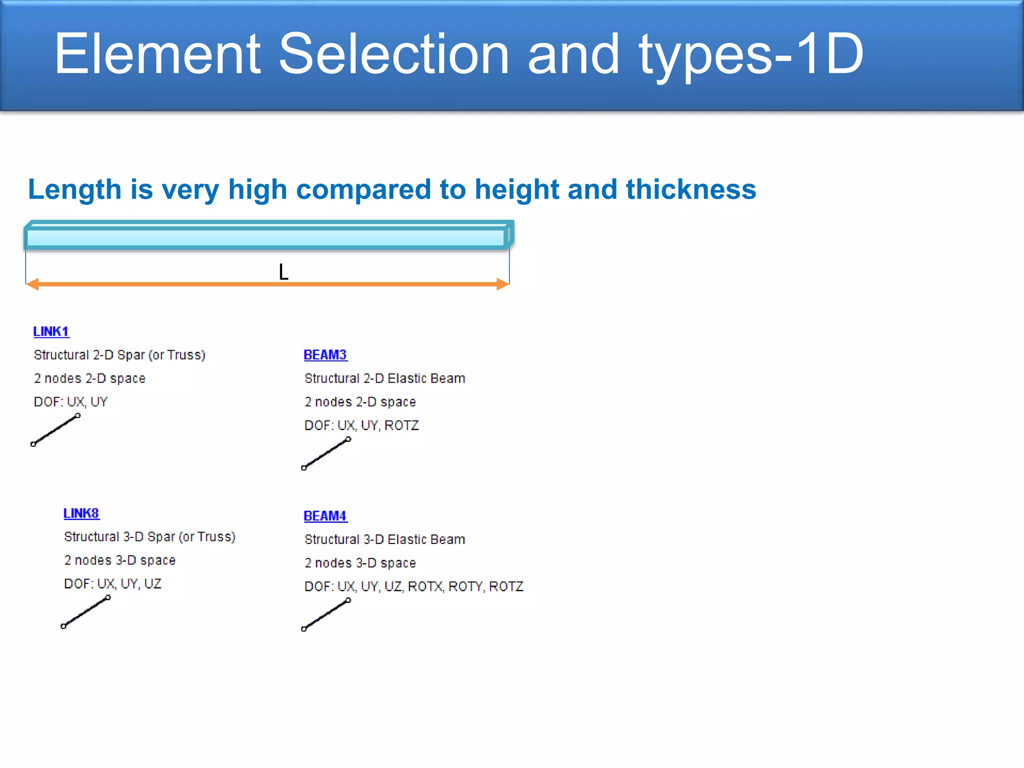
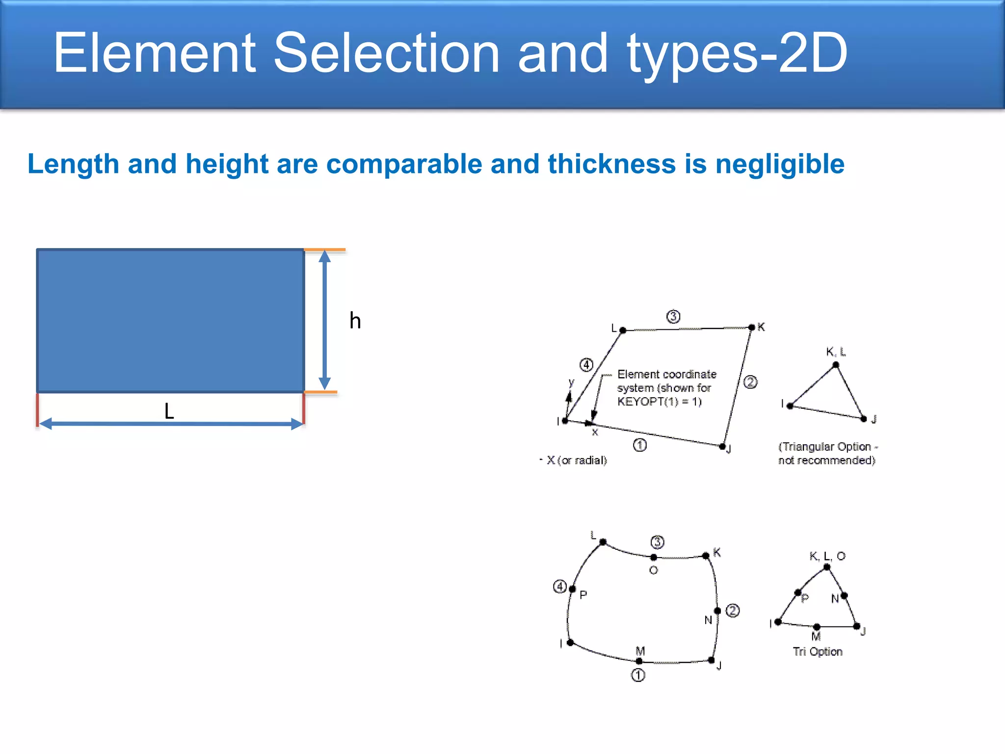
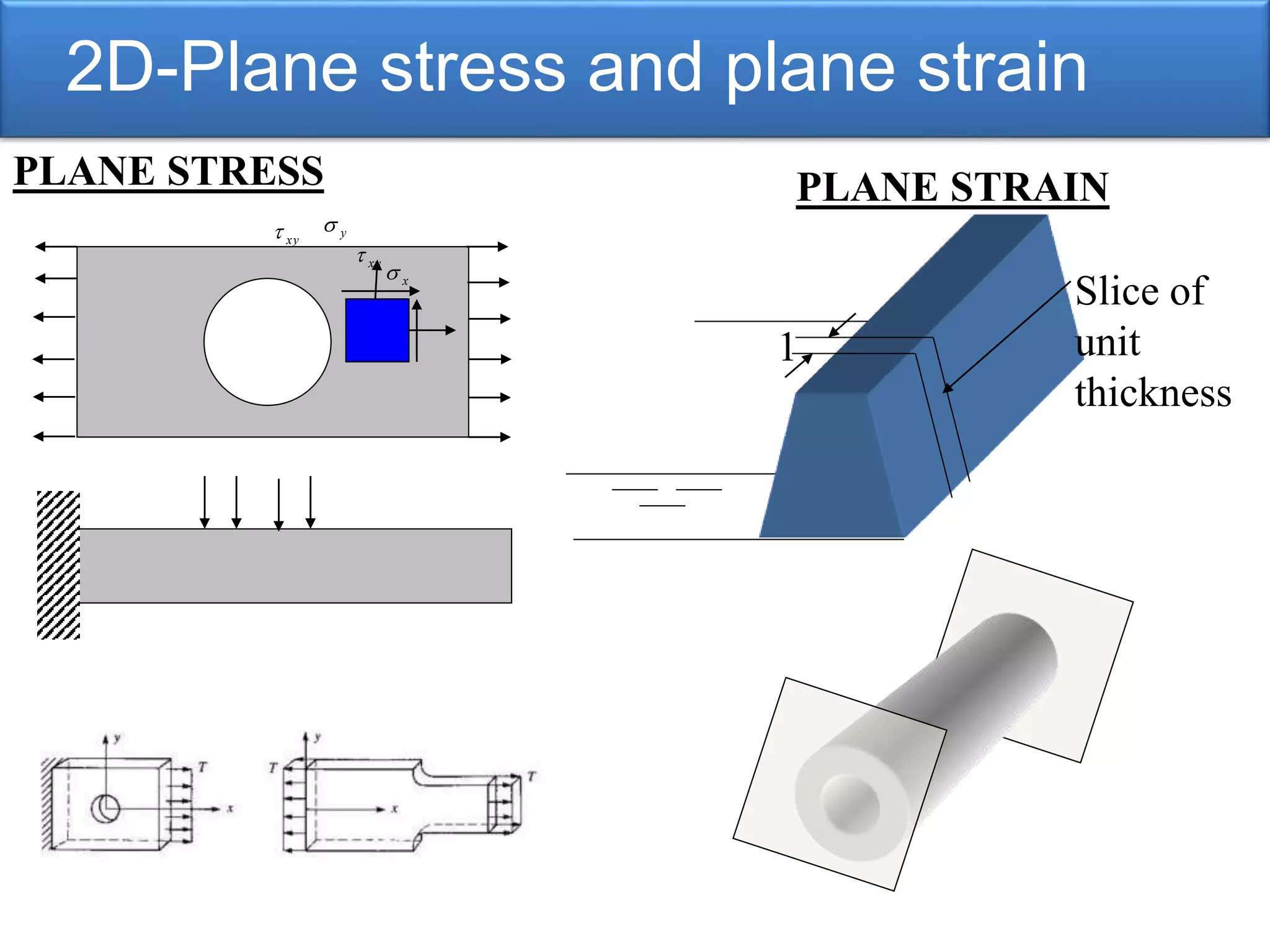
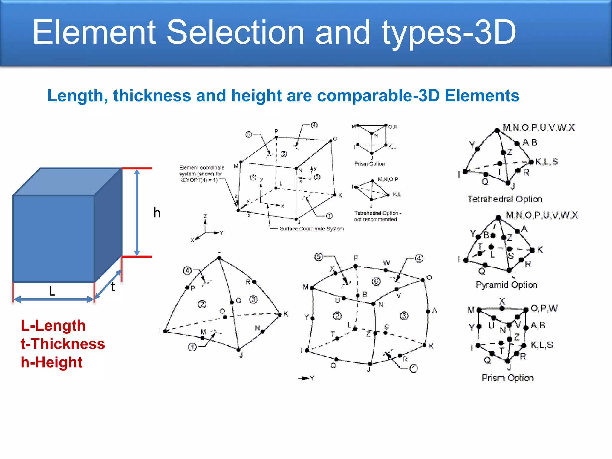
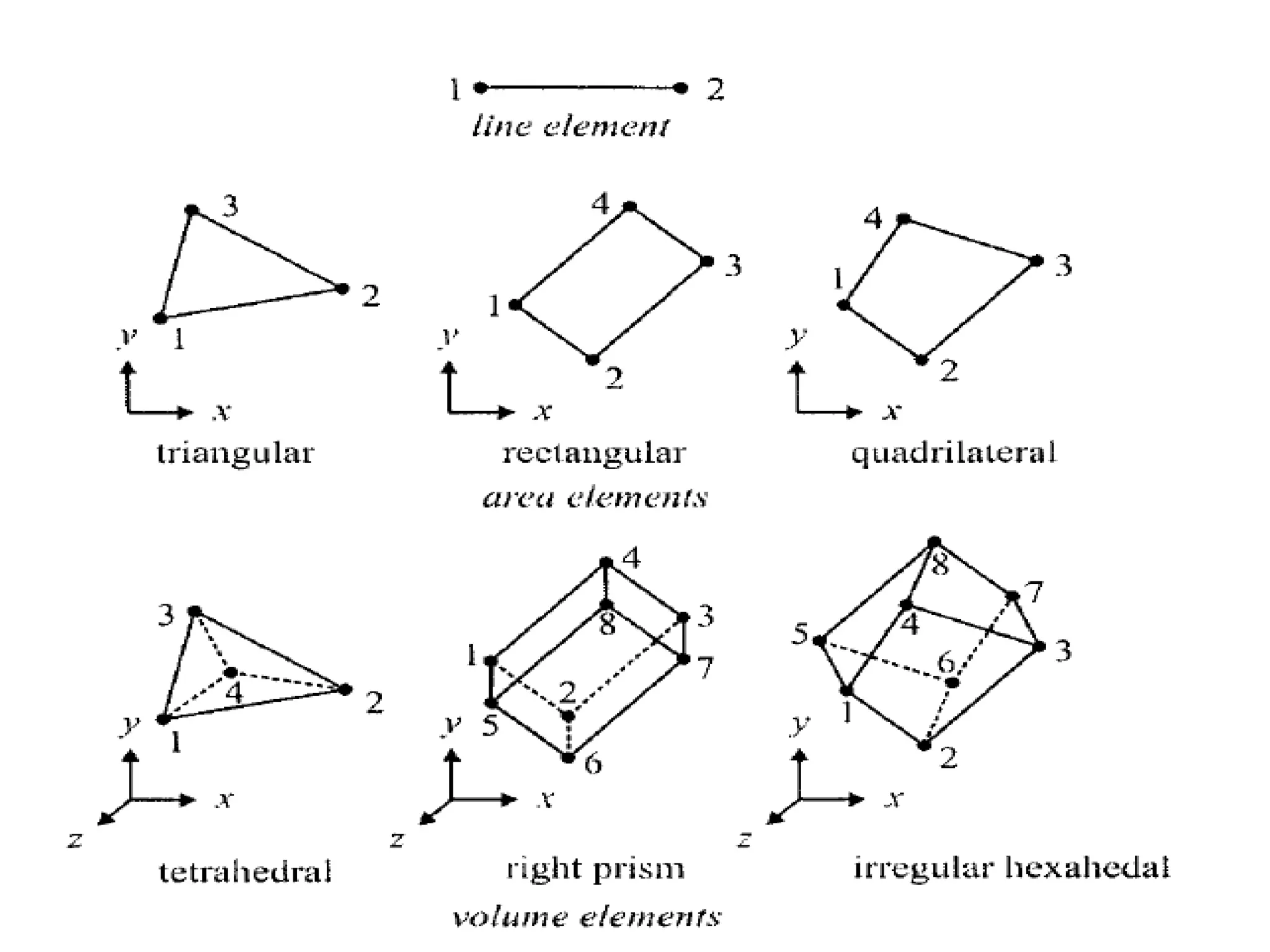
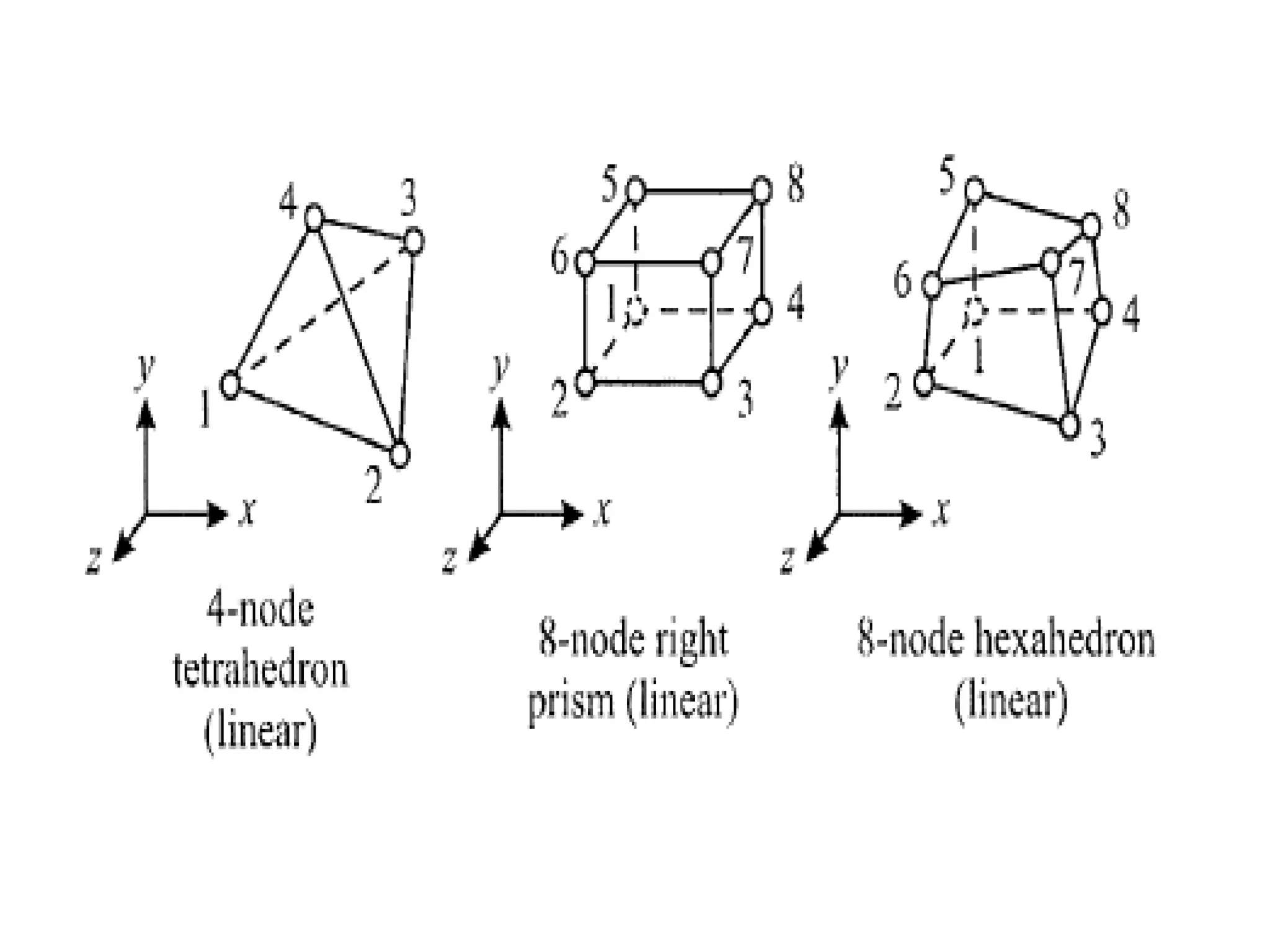
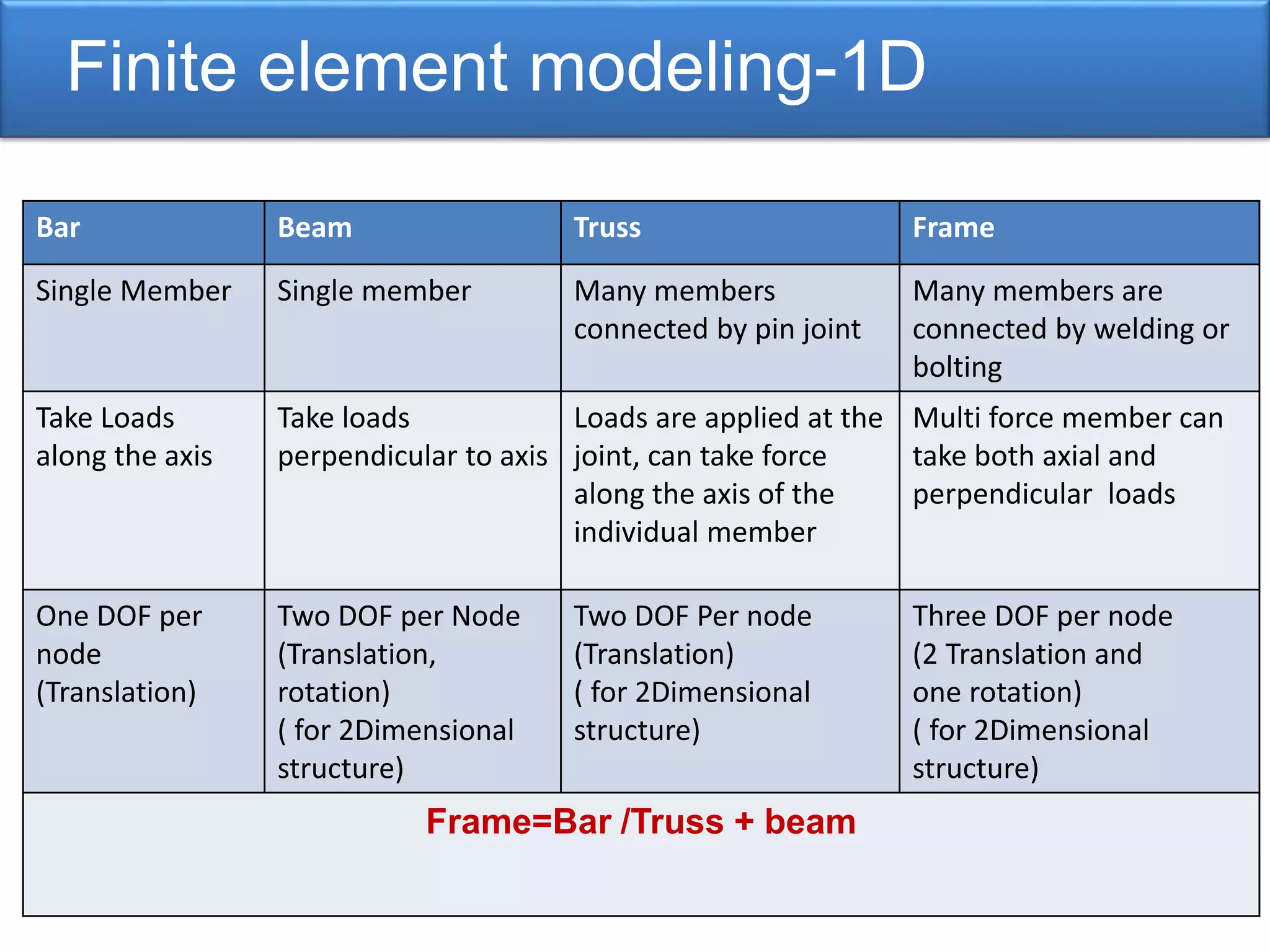
Techniques in geometric modeling including top-down and bottom-up approaches, and limitations in geometries.Discussion on various element types (1D, 2D, 3D) used in finite element modeling and their applications.
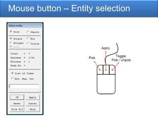
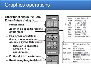
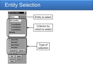
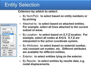
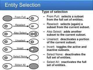
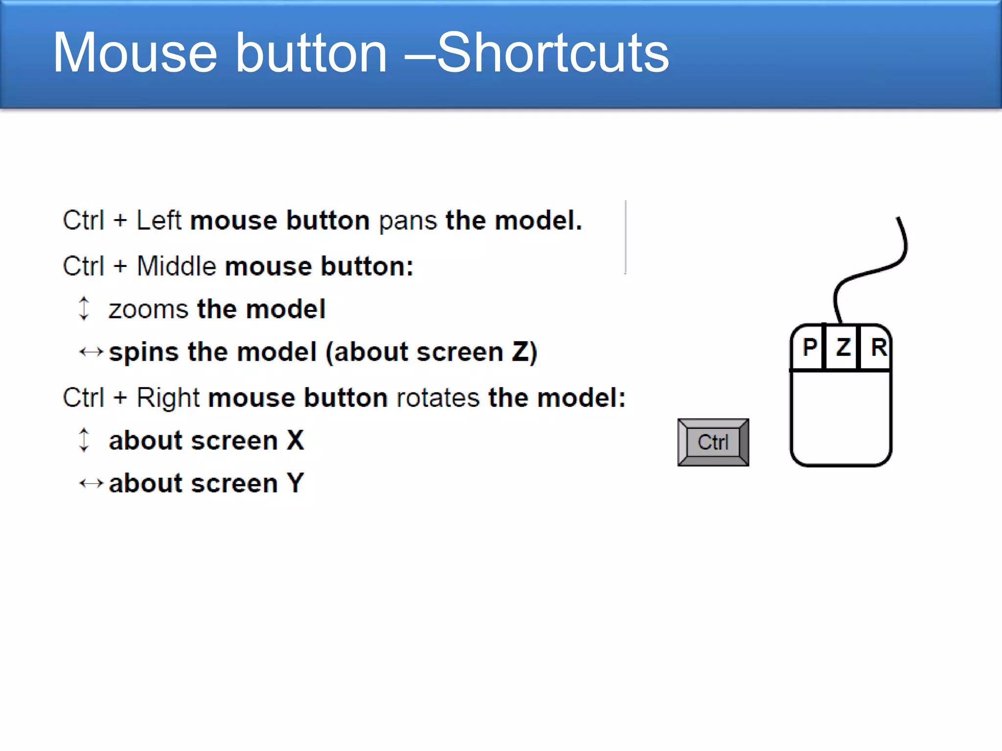
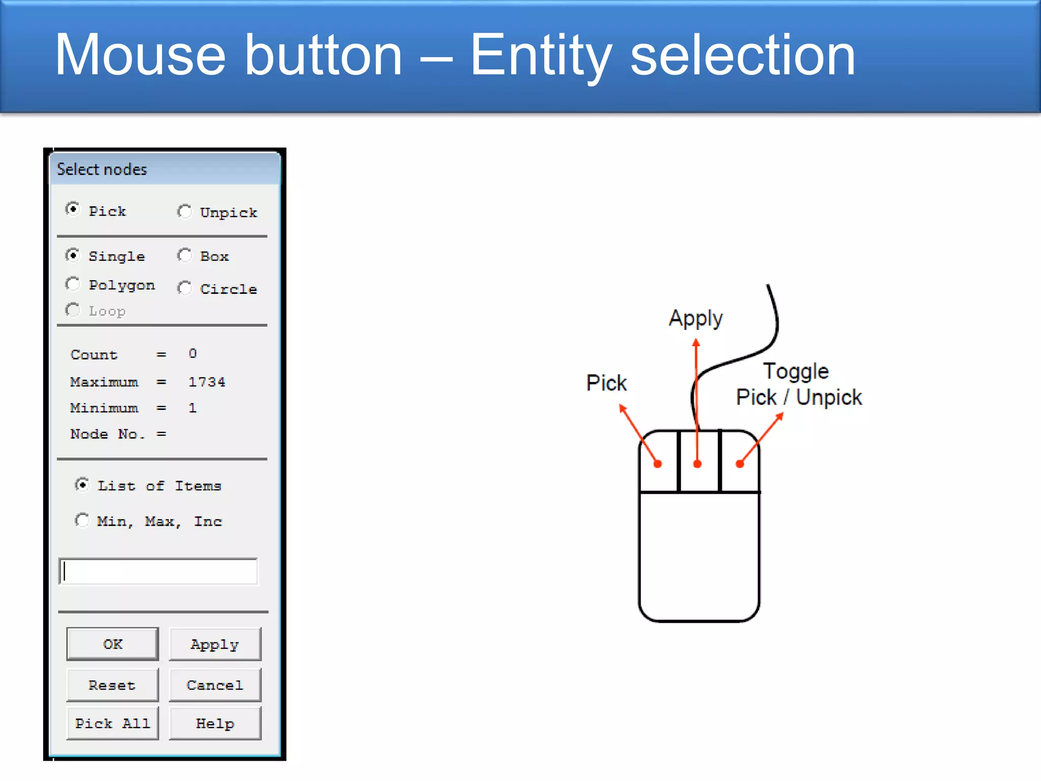
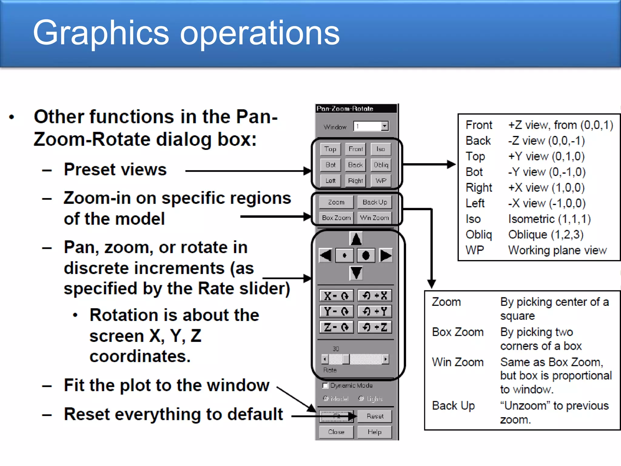
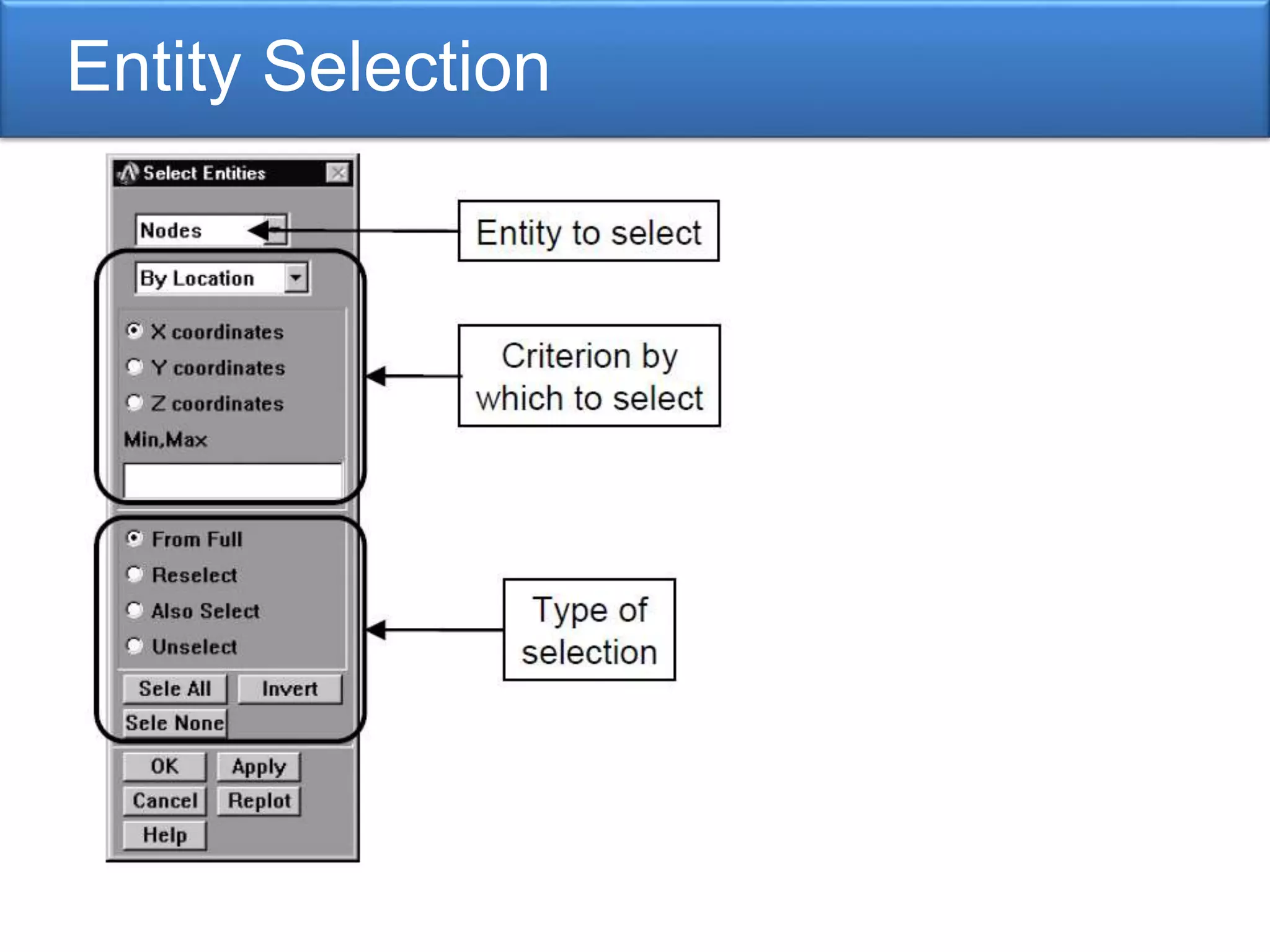
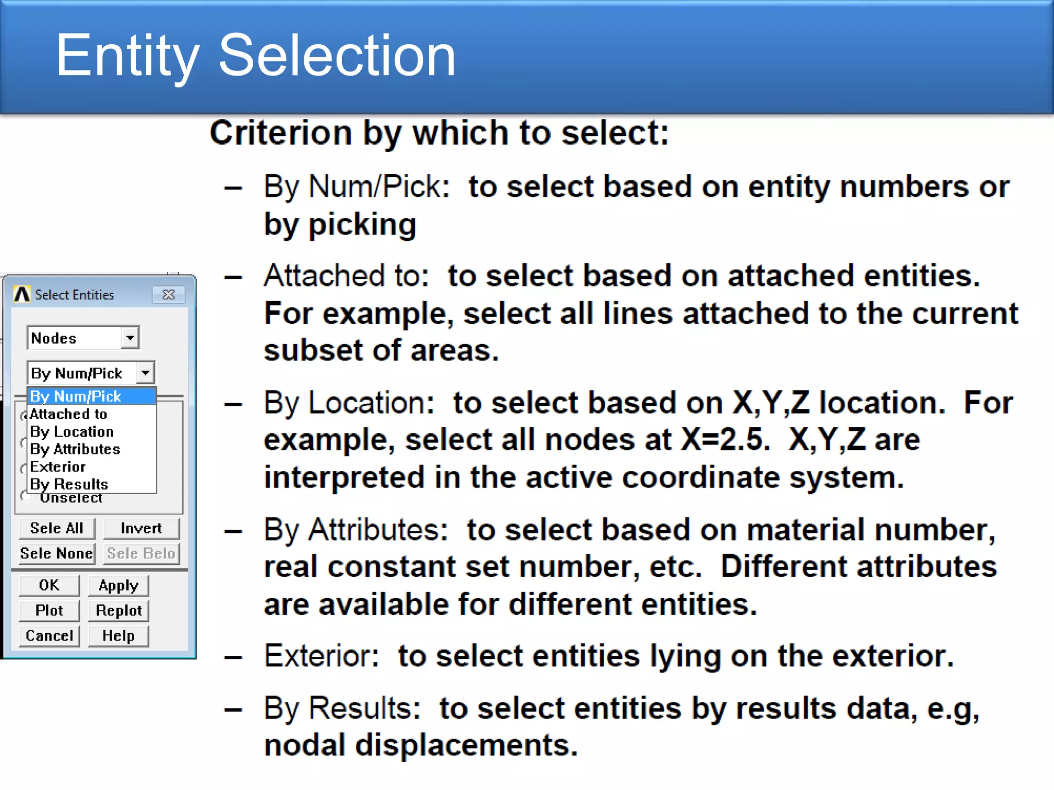
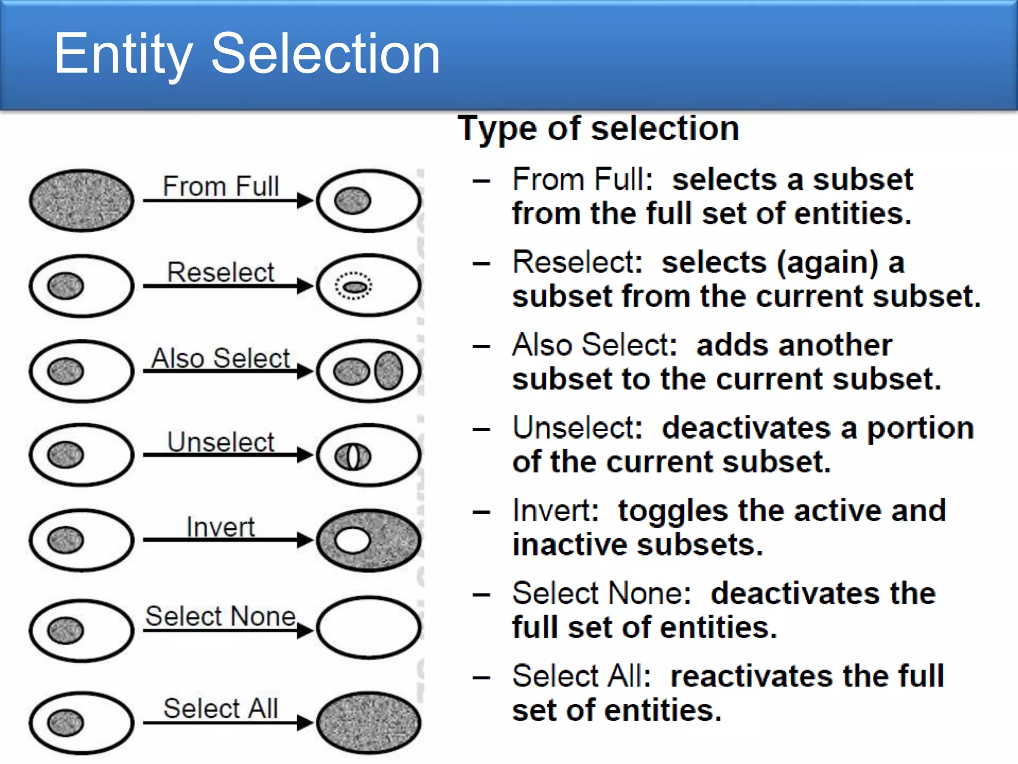
Methods for entity selection and graphics operations within the ANSYS interface.
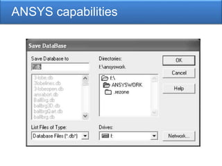
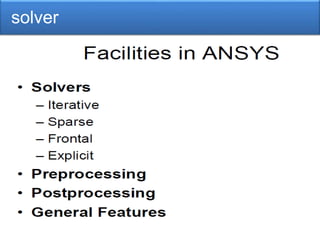
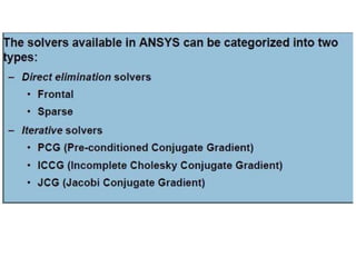
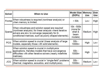
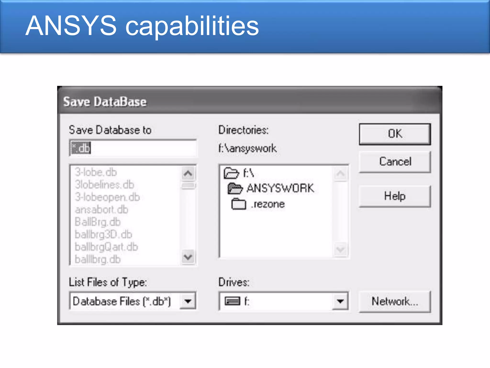
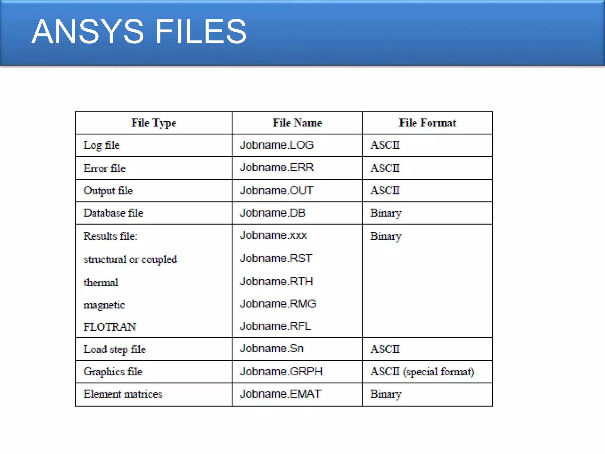
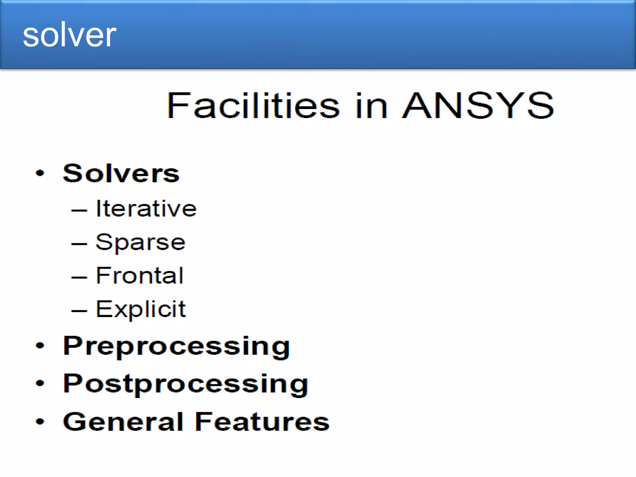
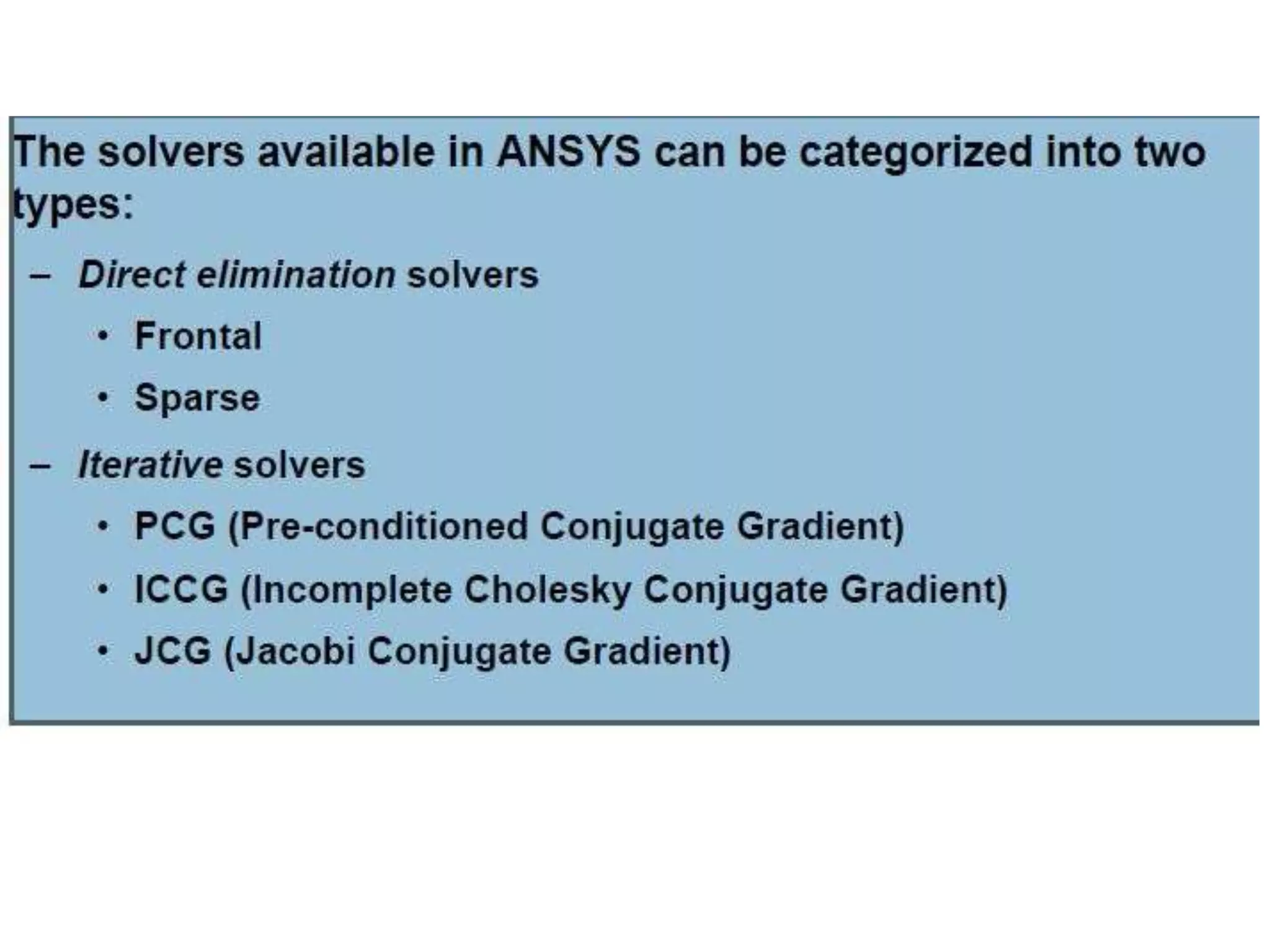
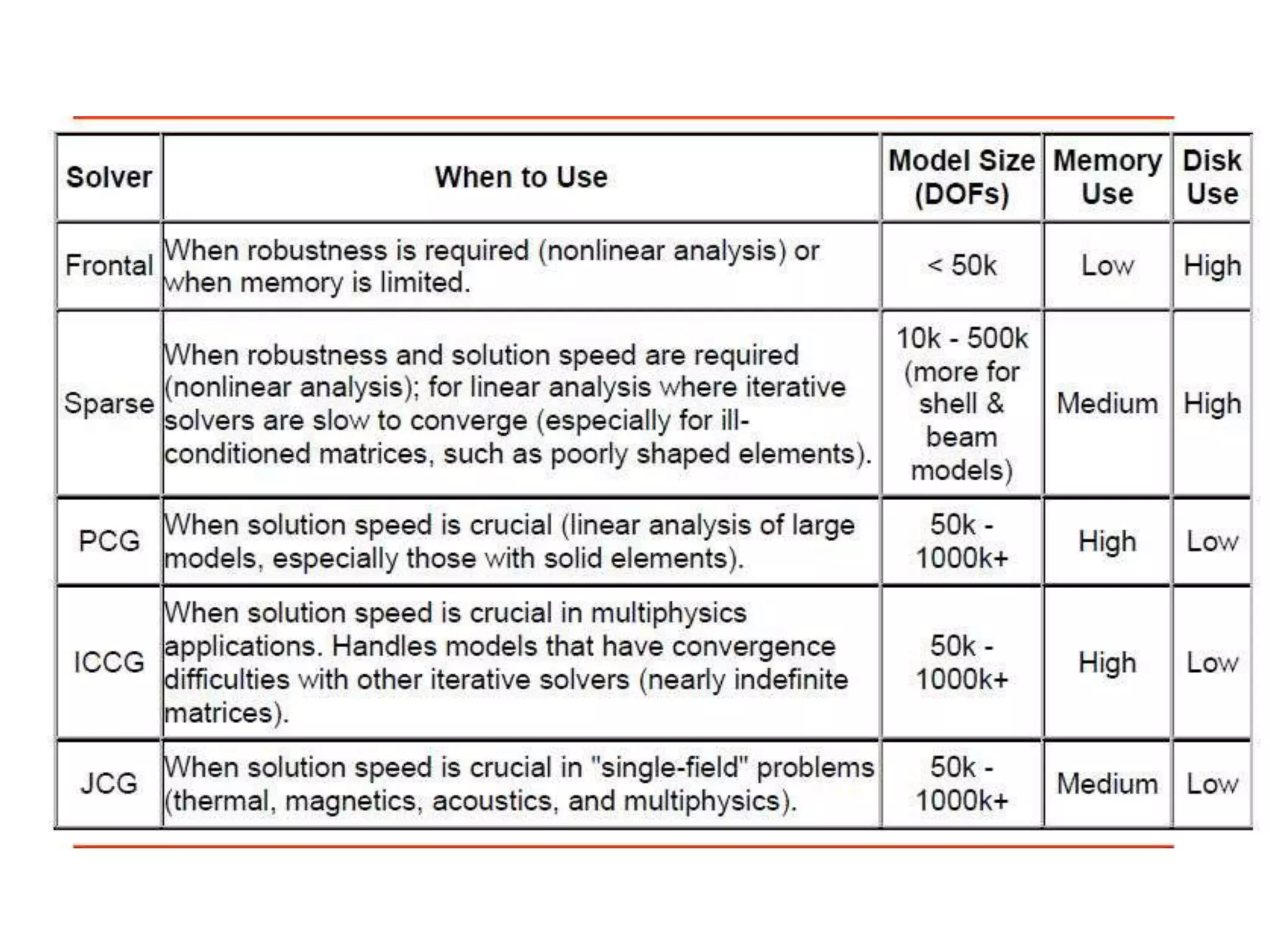
Focus on file management within ANSYS and an overview of the solver used for analysis.


