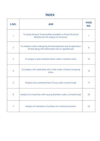
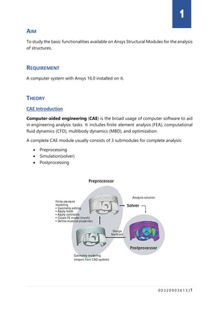
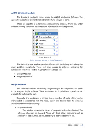
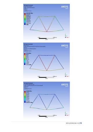
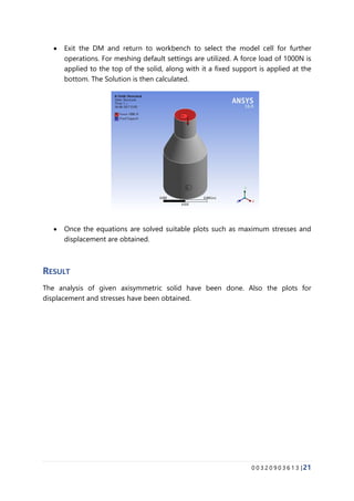
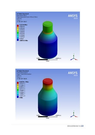
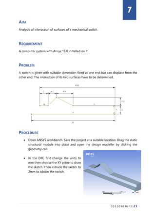
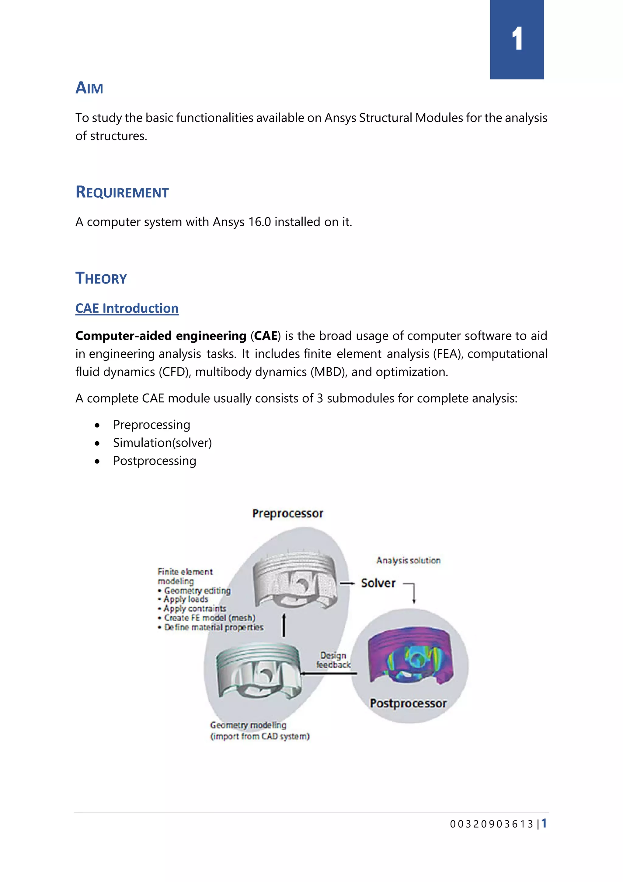
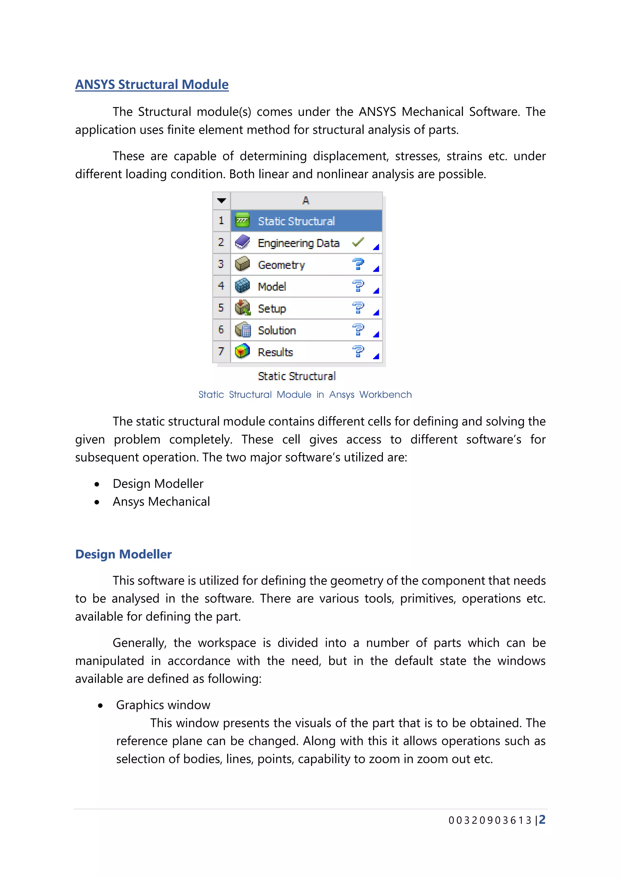
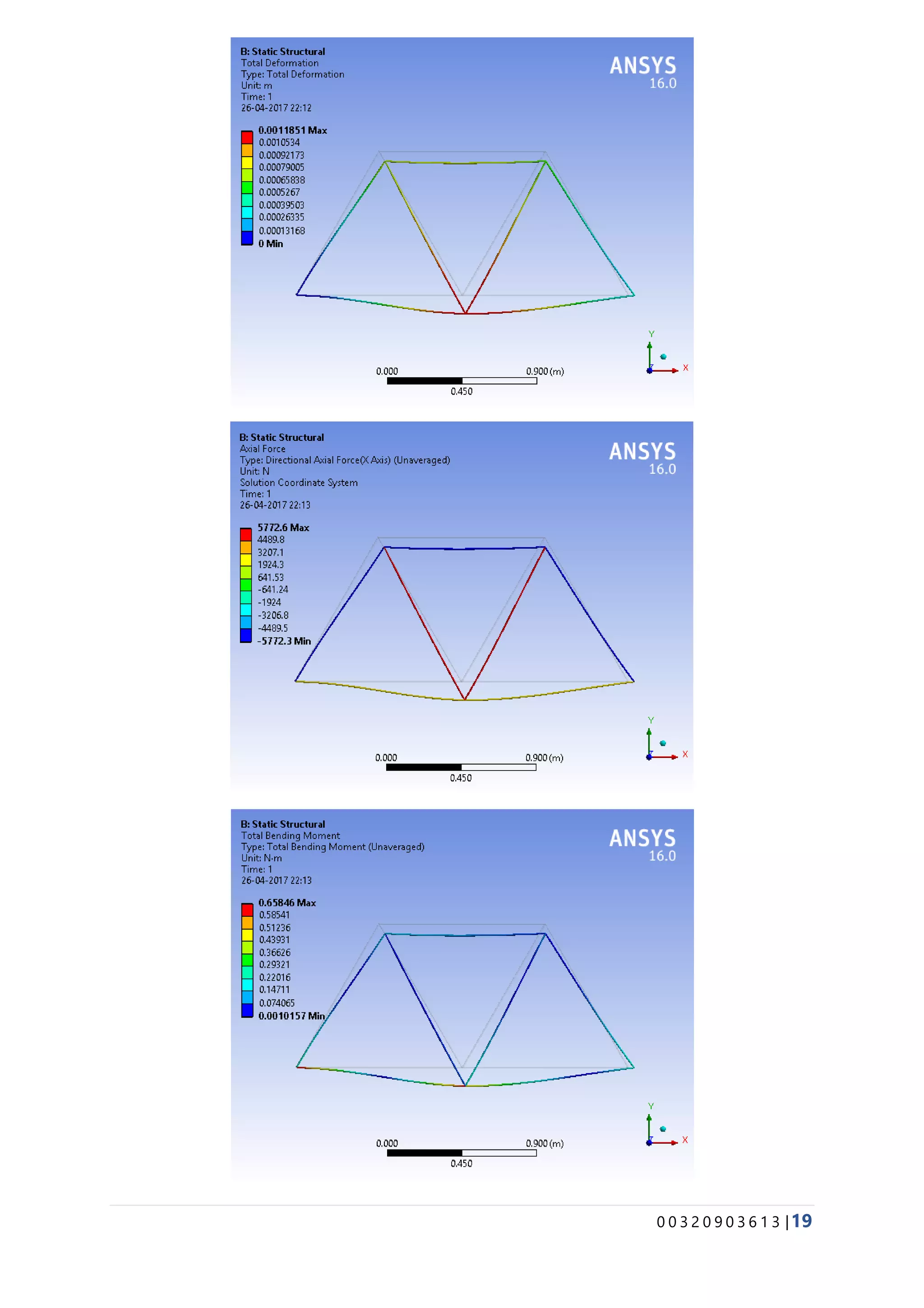
KEMBAR78
Engineering System Modelling and Simulation Lab | PDF
ENGINEERING SYSTEM
MODELLING AND
SIMULATIONS LAB
ETME - 452
SUBMITTED TO SUBMITTED BY
Dr. Anurag Dixit Vishal Singh
MAE – 8th
Sem
00320903613
INDEX
S.NO. AIM
PAGE
NO.
1
To study the basic functionalities available on Ansys Structural
Modules for the analysis of structures.
1
2
To analyse a solid undergoing thermal expansion due to application
of heat along with deformation due to applied load.
6
3 To analyse a steel cantilever beam under a constant stress. 10
4
To analyse a thin steel plate with a hole under a linearly increasing
stress.
13
5 Analysis of an overhead hoist (Truss) under constant load. 17
6 Analysis of a round bar with varying diameter under a constant load. 20
7 Analysis of interaction of surfaces of a mechanical switch. 23
0 0 3 2 0 9 0 3 6 1 3 |1
AIM
To study the basic functionalities available on Ansys Structural Modules for the analysis
of structures.
REQUIREMENT
A computer system with Ansys 16.0 installed on it.
THEORY
CAE Introduction
Computer-aided engineering (CAE) is the broad usage of computer software to aid
in engineering analysis tasks. It includes finite element analysis (FEA), computational
fluid dynamics (CFD), multibody dynamics (MBD), and optimization.
A complete CAE module usually consists of 3 submodules for complete analysis:
• Preprocessing
• Simulation(solver)
• Postprocessing
1
0 0 3 2 0 9 0 3 6 1 3 |2
ANSYS Structural Module
The Structural module(s) comes under the ANSYS Mechanical Software. The
application uses finite element method for structural analysis of parts.
These are capable of determining displacement, stresses, strains etc. under
different loading condition. Both linear and nonlinear analysis are possible.
The static structural module contains different cells for defining and solving the
given problem completely. These cell gives access to different software’s for
subsequent operation. The two major software’s utilized are:
• Design Modeller
• Ansys Mechanical
Design Modeller
This software is utilized for defining the geometry of the component that needs
to be analysed in the software. There are various tools, primitives, operations etc.
available for defining the part.
Generally, the workspace is divided into a number of parts which can be
manipulated in accordance with the need, but in the default state the windows
available are defined as following:
• Graphics window
This window presents the visuals of the part that is to be obtained. The
reference plane can be changed. Along with this it allows operations such as
selection of bodies, lines, points, capability to zoom in zoom out etc.
Static Structural Module in Ansys Workbench
0 0 3 2 0 9 0 3 6 1 3 |3
• Detail View
It gives the required information about the selected entities.
• Sketching & Modelling
The modelling bar presents the tree outline for the model and the
sketching tab gives access to drafting tools to draw 2D drawing.
• Selection bar
Graphic Windows in Ansys Design Modeller
Detail View in Ansys Design Modeller
Selection bar in Ansys Design Modeller
0 0 3 2 0 9 0 3 6 1 3 |4
The selection bar offers different tools to make selection and have the
complete directory for different operations in create, concepts, tools (Extrusion,
hole, sweep etc.)
ANSYS Mechanical
Once the designing part is complete it does all the preprocessing such as mesh
generation, solving and post processing such as stress contours are generated by this
software. Similar to that of DM its workspace is divided into different windows for
different tasks.
These are discussed as following:
• Graphic Window
It shows the current state of the object which can be viewed along
different references. Along with this it comes along with selection making,
scaling, rotation operations.
• Detail View
It gives the details about the entities in current selection.
• Outline
It presents an outline tree for various operations that had been done with
workpiece. It allows selection of mesh, arranging the boundary conditions,
initialization of solutions, study of results etc.
It is a very useful tool as all the preprocessing, solving and
postprocessing can be arranged and managed with this only. Thus, providing
a very convenient way for problem analyzation.
Graphic Window in ANSYS Mechanical
0 0 3 2 0 9 0 3 6 1 3 |5
• Selection Window
It allows selection of various tools, unit, points, bodies, planes etc. Along
with this it provides dynamic options for mesh operations, boundary condition
(Environment Constraints) and solutions results that can be implied to the
workpiece in study.
RESULT
The various capabilities of ANSYS Structural Modules have been studied completely
that will be utilized in simulation and analysis of objects.
Outline in ANSYS Mechanical
Selection bar in ANSYS Mechanical
0 0 3 2 0 9 0 3 6 1 3 |6
AIM
To analyse a solid undergoing thermal expansion due to application of heat along with
deformation due to applied load.
REQUIREMENT
A computer system with Ansys 16.0 installed on it.
PROBLEM
A thin aluminium cylinder of length 1m and inner and outer radius 0.2m & 0.21m
respectively. The cylinder is kept fixed at one end and at the other end a tensile load
of 200 kPa is applied. The fixed end of the cylinder is at 22 o
C (the ambient
temperature) and the free end at 23 o
C (all other sides are insulated). The cylinder
expands due to the heat flow.
PROCEDURE
• Open ANSYS workbench. Save the project at a suitable location. Drag and place
the Steady State – Thermal module.
• Open the Engineering Data cell to select Aluminium Alloy from the ANSYS
database and add it to the list of material.
• Open the Geometry cell. Select the front plane and sketch two circles of radius
0.2m and 0.1m. Add extrude of 1m normal to the sketch.
2
0 0 3 2 0 9 0 3 6 1 3 |7
• Close the design modeller and open the model cell from the workbench.
• Choose the geometry from the outline and change the material from steel to
aluminium. Select the mesh and generate it with the default setting but high
smoothing. Apply the temperature conditions and insulated surface condition
to the appropriate walls. Solve the system for 5s and obtain a temperature plot
of the system.
• Close the window and return to the workbench. Drag the Static Structure
Module and share the cell values of thermal analysis with it.
0 0 3 2 0 9 0 3 6 1 3 |8
• Open the Model Cell. Change the material to Aluminium and prepare the Mesh
with similar conditions. In the imported load change the time to all them import
all the data. Change the analysis time to 5s. Apply the fixed end and the load
boundary condition then click solve.
• After the solution obtain the contours of displacement and the resultant
stresses.
RESULT
The analysis for the given solid under thermal and tensile loads have been completed.
Also the contours for displacement and resultant stresses have been obtained
0 0 3 2 0 9 0 3 6 1 3 |9
0 0 3 2 0 9 0 3 6 1 3 |10
AIM
To analyse a steel cantilever beam under a constant stress.
REQUIREMENT
A computer system with Ansys 16.0 installed on it.
PROBLEM
A steel cantilever beam of dimensions 200mm x 25mm x 20mm is kept fixed at one
end. A constant stress of 0.5MPa is applied upon the 200mm x 25mm cross – section
on the top.
PROCEDURE
• Open Ansys Workbench. Save the project at a suitable location. Drag the Static
Structural Module from the toolbox to the project schematics. Click to open
the geometry.
• Once DM is opened, click on the units to change the length from m to mm.
Choose the xy plane to start sketching then extrude the area in the normal
direction to obtain the bar.
3
0 0 3 2 0 9 0 3 6 1 3 |11
• Close the design modeller. In the ANSYS workbench click on the model cell to
open the ANSYS Mechanical.
• Generate the mesh with the default settings. For the boundary condition select
pressure from load tab apply a load on the top face of the beam and add a
fixed support at one end of the beam. Calculate the result.
• Plot the displacement and the equivalent stress contours.
RESULT
The analysis of a cantilever beam under a constant load have been done. The
displacement and equivalent stresses plot had also been obtained.
0 0 3 2 0 9 0 3 6 1 3 |12
0 0 3 2 0 9 0 3 6 1 3 |13
AIM
To analyse a thin steel plate with a hole under a linearly increasing stress.
REQUIREMENT
A computer system with Ansys 16.0 installed on it.
PROBLEM
A thin steel plate of dimension 10cm x 10cm has a hole at the center whose radius is
1cm. A linearly increasing stress on the steel plate is applied at two edges.
PROCEDURE
• Open ANSYS Workbench. Save the project at a suitable location. Drag the Static
Structural Module. Click on the geometry to open the Design Modeller.
• In the DM, change the units to cm.
Select the XY plane and sketch a
square with edge 10cm and a circle at
the center of the square with radius
1cm. Select all the entities and
extrude the structure to 0.1cm to
obtain a thin plate. Close the design
modeller.
4
0 0 3 2 0 9 0 3 6 1 3 |14
• In the workbench open the Model cell to open the ANSYS mechanical software.
First generate the mesh by changing the transition to slow and smoothening to
high and click generate mesh to obtain the mesh.
• In the Analysis Setting change the number of steps to 3 and assign each step a
time period of 1 sec. Select the pressure condition from the loads tab and apply
it on the required edge. In the detail section change magnitude to tabular form
than enter the data in the table as required, Repeat the step for the other edge.
0 0 3 2 0 9 0 3 6 1 3 |15
• Solve the system of equations and plot the deformation and the equivalent
stresses contours.
RESULT
The analysis of a steel plate with a hole undergoing a gradual stress on edges have
been done. The displacement and stress contours have also been obtained.
0 0 3 2 0 9 0 3 6 1 3 |16
0 0 3 2 0 9 0 3 6 1 3 |17
AIM
Analysis of an overhead hoist (Truss) under constant load.
REQUIREMENT
A computer system with Ansys 16.0 installed on it.
PROBLEM
The hoist is modelled as a simple, pin-jointed truss that is constrained at the left-hand
end and mounted on rollers at the right-hand end. The members can rotate freely at
the joints. The truss is prevented from moving out of plane. A 10 kN load is applied.
PROCEDURE
• Open the ANSYS Workbench. Drag the static structural module in the project
schematics. Open the geometry cell for designing the truss.
• In the DM select the XY plane to draw a line structure of the truss and add
dimensions to it. Select line from sketch in the concept bar to add a single line
structure from the sketch. Add a circular cross section of 5 mm radius and in
the line body add this cross section to obtain the truss structure.
• Close the DM and return to workbench to open the model cell for analysis of
the truss structure. Add a mesh to the structure with smooth transitions and
high smoothing in the mesh setting, then click generate mesh to obtain the
final mesh.
5
0 0 3 2 0 9 0 3 6 1 3 |18
• From the support tab add a fixed support and a displacement support (Roller)
with 0 displacement along Y. Add force from load to the structure along Y axis.
• Solve the model and obtain solutions for displacement, along with bending
moment and axial stresses from the beam result tab.
RESULT
The analysis of the given truss members has been completed. Suitable plots have also
been obtained from it.
0 0 3 2 0 9 0 3 6 1 3 |19
0 0 3 2 0 9 0 3 6 1 3 |20
AIM
Analysis of a round bar with varying diameter under a constant load.
REQUIREMENT
A computer system with Ansys 16.0 installed on it.
PROBLEM
A round bar with varying diameter has a total load of 1000 N applied to its top face.
The bottom of the bar is completely fixed.
PROCEDURE
• Open the ANSYS Workbench. Drag the static structural module and open the
geometry cell to sketch the part.
• Select the XY plane to begin
sketching. Once the sketch of the
cross section is created, revolve
operation is used to obtain the
solid about the centreline.
6
0 0 3 2 0 9 0 3 6 1 3 |21
• Exit the DM and return to workbench to select the model cell for further
operations. For meshing default settings are utilized. A force load of 1000N is
applied to the top of the solid, along with it a fixed support is applied at the
bottom. The Solution is then calculated.
• Once the equations are solved suitable plots such as maximum stresses and
displacement are obtained.
RESULT
The analysis of given axisymmetric solid have been done. Also the plots for
displacement and stresses have been obtained.
0 0 3 2 0 9 0 3 6 1 3 |22
0 0 3 2 0 9 0 3 6 1 3 |23
AIM
Analysis of interaction of surfaces of a mechanical switch.
REQUIREMENT
A computer system with Ansys 16.0 installed on it.
PROBLEM
A switch is given with suitable dimension fixed at one end but can displace from the
other end. The interaction of its two surfaces have to be determined.
PROCEDURE
• Open ANSYS workbench. Save the project at a suitable location. Drag the static
structural module into place and open the design modeller by clicking the
geometry cell.
• In the DM, first change the units to
mm then choose the XY plane to draw
the sketch. Then extrude the sketch to
2mm to obtain the switch.
7
0 0 3 2 0 9 0 3 6 1 3 |24
• After closing DM return to workbench and open model cell for further
operation.
• Add connections, then no separation contact region by right clicking the model
in the outline tree. Then add the fixed support and the displacement of -3mm
in y – direction to one of the edge. Then solve the problem.
• After this get plots for total deformation and equivalent stresses in the part.
RESULT
The analysis of the given switch connection has been done. Stress and deformation
contours have also been obtained.
0 0 3 2 0 9 0 3 6 1 3 |25

Engineering System Modelling and Simulation Lab

  • 1.
    ENGINEERING SYSTEM MODELLING AND SIMULATIONSLAB ETME - 452 SUBMITTED TO SUBMITTED BY Dr. Anurag Dixit Vishal Singh MAE – 8th Sem 00320903613
  • 2.
    INDEX S.NO. AIM PAGE NO. 1 To studythe basic functionalities available on Ansys Structural Modules for the analysis of structures. 1 2 To analyse a solid undergoing thermal expansion due to application of heat along with deformation due to applied load. 6 3 To analyse a steel cantilever beam under a constant stress. 10 4 To analyse a thin steel plate with a hole under a linearly increasing stress. 13 5 Analysis of an overhead hoist (Truss) under constant load. 17 6 Analysis of a round bar with varying diameter under a constant load. 20 7 Analysis of interaction of surfaces of a mechanical switch. 23
  • 3.
    0 0 32 0 9 0 3 6 1 3 |1 AIM To study the basic functionalities available on Ansys Structural Modules for the analysis of structures. REQUIREMENT A computer system with Ansys 16.0 installed on it. THEORY CAE Introduction Computer-aided engineering (CAE) is the broad usage of computer software to aid in engineering analysis tasks. It includes finite element analysis (FEA), computational fluid dynamics (CFD), multibody dynamics (MBD), and optimization. A complete CAE module usually consists of 3 submodules for complete analysis: • Preprocessing • Simulation(solver) • Postprocessing 1
  • 4.
    0 0 32 0 9 0 3 6 1 3 |2 ANSYS Structural Module The Structural module(s) comes under the ANSYS Mechanical Software. The application uses finite element method for structural analysis of parts. These are capable of determining displacement, stresses, strains etc. under different loading condition. Both linear and nonlinear analysis are possible. The static structural module contains different cells for defining and solving the given problem completely. These cell gives access to different software’s for subsequent operation. The two major software’s utilized are: • Design Modeller • Ansys Mechanical Design Modeller This software is utilized for defining the geometry of the component that needs to be analysed in the software. There are various tools, primitives, operations etc. available for defining the part. Generally, the workspace is divided into a number of parts which can be manipulated in accordance with the need, but in the default state the windows available are defined as following: • Graphics window This window presents the visuals of the part that is to be obtained. The reference plane can be changed. Along with this it allows operations such as selection of bodies, lines, points, capability to zoom in zoom out etc. Static Structural Module in Ansys Workbench
  • 5.
    0 0 32 0 9 0 3 6 1 3 |3 • Detail View It gives the required information about the selected entities. • Sketching & Modelling The modelling bar presents the tree outline for the model and the sketching tab gives access to drafting tools to draw 2D drawing. • Selection bar Graphic Windows in Ansys Design Modeller Detail View in Ansys Design Modeller Selection bar in Ansys Design Modeller
  • 6.
    0 0 32 0 9 0 3 6 1 3 |4 The selection bar offers different tools to make selection and have the complete directory for different operations in create, concepts, tools (Extrusion, hole, sweep etc.) ANSYS Mechanical Once the designing part is complete it does all the preprocessing such as mesh generation, solving and post processing such as stress contours are generated by this software. Similar to that of DM its workspace is divided into different windows for different tasks. These are discussed as following: • Graphic Window It shows the current state of the object which can be viewed along different references. Along with this it comes along with selection making, scaling, rotation operations. • Detail View It gives the details about the entities in current selection. • Outline It presents an outline tree for various operations that had been done with workpiece. It allows selection of mesh, arranging the boundary conditions, initialization of solutions, study of results etc. It is a very useful tool as all the preprocessing, solving and postprocessing can be arranged and managed with this only. Thus, providing a very convenient way for problem analyzation. Graphic Window in ANSYS Mechanical
  • 7.
    0 0 32 0 9 0 3 6 1 3 |5 • Selection Window It allows selection of various tools, unit, points, bodies, planes etc. Along with this it provides dynamic options for mesh operations, boundary condition (Environment Constraints) and solutions results that can be implied to the workpiece in study. RESULT The various capabilities of ANSYS Structural Modules have been studied completely that will be utilized in simulation and analysis of objects. Outline in ANSYS Mechanical Selection bar in ANSYS Mechanical
  • 8.
    0 0 32 0 9 0 3 6 1 3 |6 AIM To analyse a solid undergoing thermal expansion due to application of heat along with deformation due to applied load. REQUIREMENT A computer system with Ansys 16.0 installed on it. PROBLEM A thin aluminium cylinder of length 1m and inner and outer radius 0.2m & 0.21m respectively. The cylinder is kept fixed at one end and at the other end a tensile load of 200 kPa is applied. The fixed end of the cylinder is at 22 o C (the ambient temperature) and the free end at 23 o C (all other sides are insulated). The cylinder expands due to the heat flow. PROCEDURE • Open ANSYS workbench. Save the project at a suitable location. Drag and place the Steady State – Thermal module. • Open the Engineering Data cell to select Aluminium Alloy from the ANSYS database and add it to the list of material. • Open the Geometry cell. Select the front plane and sketch two circles of radius 0.2m and 0.1m. Add extrude of 1m normal to the sketch. 2
  • 9.
    0 0 32 0 9 0 3 6 1 3 |7 • Close the design modeller and open the model cell from the workbench. • Choose the geometry from the outline and change the material from steel to aluminium. Select the mesh and generate it with the default setting but high smoothing. Apply the temperature conditions and insulated surface condition to the appropriate walls. Solve the system for 5s and obtain a temperature plot of the system. • Close the window and return to the workbench. Drag the Static Structure Module and share the cell values of thermal analysis with it.
  • 10.
    0 0 32 0 9 0 3 6 1 3 |8 • Open the Model Cell. Change the material to Aluminium and prepare the Mesh with similar conditions. In the imported load change the time to all them import all the data. Change the analysis time to 5s. Apply the fixed end and the load boundary condition then click solve. • After the solution obtain the contours of displacement and the resultant stresses. RESULT The analysis for the given solid under thermal and tensile loads have been completed. Also the contours for displacement and resultant stresses have been obtained
  • 11.
    0 0 32 0 9 0 3 6 1 3 |9
  • 12.
    0 0 32 0 9 0 3 6 1 3 |10 AIM To analyse a steel cantilever beam under a constant stress. REQUIREMENT A computer system with Ansys 16.0 installed on it. PROBLEM A steel cantilever beam of dimensions 200mm x 25mm x 20mm is kept fixed at one end. A constant stress of 0.5MPa is applied upon the 200mm x 25mm cross – section on the top. PROCEDURE • Open Ansys Workbench. Save the project at a suitable location. Drag the Static Structural Module from the toolbox to the project schematics. Click to open the geometry. • Once DM is opened, click on the units to change the length from m to mm. Choose the xy plane to start sketching then extrude the area in the normal direction to obtain the bar. 3
  • 13.
    0 0 32 0 9 0 3 6 1 3 |11 • Close the design modeller. In the ANSYS workbench click on the model cell to open the ANSYS Mechanical. • Generate the mesh with the default settings. For the boundary condition select pressure from load tab apply a load on the top face of the beam and add a fixed support at one end of the beam. Calculate the result. • Plot the displacement and the equivalent stress contours. RESULT The analysis of a cantilever beam under a constant load have been done. The displacement and equivalent stresses plot had also been obtained.
  • 14.
    0 0 32 0 9 0 3 6 1 3 |12
  • 15.
    0 0 32 0 9 0 3 6 1 3 |13 AIM To analyse a thin steel plate with a hole under a linearly increasing stress. REQUIREMENT A computer system with Ansys 16.0 installed on it. PROBLEM A thin steel plate of dimension 10cm x 10cm has a hole at the center whose radius is 1cm. A linearly increasing stress on the steel plate is applied at two edges. PROCEDURE • Open ANSYS Workbench. Save the project at a suitable location. Drag the Static Structural Module. Click on the geometry to open the Design Modeller. • In the DM, change the units to cm. Select the XY plane and sketch a square with edge 10cm and a circle at the center of the square with radius 1cm. Select all the entities and extrude the structure to 0.1cm to obtain a thin plate. Close the design modeller. 4
  • 16.
    0 0 32 0 9 0 3 6 1 3 |14 • In the workbench open the Model cell to open the ANSYS mechanical software. First generate the mesh by changing the transition to slow and smoothening to high and click generate mesh to obtain the mesh. • In the Analysis Setting change the number of steps to 3 and assign each step a time period of 1 sec. Select the pressure condition from the loads tab and apply it on the required edge. In the detail section change magnitude to tabular form than enter the data in the table as required, Repeat the step for the other edge.
  • 17.
    0 0 32 0 9 0 3 6 1 3 |15 • Solve the system of equations and plot the deformation and the equivalent stresses contours. RESULT The analysis of a steel plate with a hole undergoing a gradual stress on edges have been done. The displacement and stress contours have also been obtained.
  • 18.
    0 0 32 0 9 0 3 6 1 3 |16
  • 19.
    0 0 32 0 9 0 3 6 1 3 |17 AIM Analysis of an overhead hoist (Truss) under constant load. REQUIREMENT A computer system with Ansys 16.0 installed on it. PROBLEM The hoist is modelled as a simple, pin-jointed truss that is constrained at the left-hand end and mounted on rollers at the right-hand end. The members can rotate freely at the joints. The truss is prevented from moving out of plane. A 10 kN load is applied. PROCEDURE • Open the ANSYS Workbench. Drag the static structural module in the project schematics. Open the geometry cell for designing the truss. • In the DM select the XY plane to draw a line structure of the truss and add dimensions to it. Select line from sketch in the concept bar to add a single line structure from the sketch. Add a circular cross section of 5 mm radius and in the line body add this cross section to obtain the truss structure. • Close the DM and return to workbench to open the model cell for analysis of the truss structure. Add a mesh to the structure with smooth transitions and high smoothing in the mesh setting, then click generate mesh to obtain the final mesh. 5
  • 20.
    0 0 32 0 9 0 3 6 1 3 |18 • From the support tab add a fixed support and a displacement support (Roller) with 0 displacement along Y. Add force from load to the structure along Y axis. • Solve the model and obtain solutions for displacement, along with bending moment and axial stresses from the beam result tab. RESULT The analysis of the given truss members has been completed. Suitable plots have also been obtained from it.
  • 21.
    0 0 32 0 9 0 3 6 1 3 |19
  • 22.
    0 0 32 0 9 0 3 6 1 3 |20 AIM Analysis of a round bar with varying diameter under a constant load. REQUIREMENT A computer system with Ansys 16.0 installed on it. PROBLEM A round bar with varying diameter has a total load of 1000 N applied to its top face. The bottom of the bar is completely fixed. PROCEDURE • Open the ANSYS Workbench. Drag the static structural module and open the geometry cell to sketch the part. • Select the XY plane to begin sketching. Once the sketch of the cross section is created, revolve operation is used to obtain the solid about the centreline. 6
  • 23.
    0 0 32 0 9 0 3 6 1 3 |21 • Exit the DM and return to workbench to select the model cell for further operations. For meshing default settings are utilized. A force load of 1000N is applied to the top of the solid, along with it a fixed support is applied at the bottom. The Solution is then calculated. • Once the equations are solved suitable plots such as maximum stresses and displacement are obtained. RESULT The analysis of given axisymmetric solid have been done. Also the plots for displacement and stresses have been obtained.
  • 24.
    0 0 32 0 9 0 3 6 1 3 |22
  • 25.
    0 0 32 0 9 0 3 6 1 3 |23 AIM Analysis of interaction of surfaces of a mechanical switch. REQUIREMENT A computer system with Ansys 16.0 installed on it. PROBLEM A switch is given with suitable dimension fixed at one end but can displace from the other end. The interaction of its two surfaces have to be determined. PROCEDURE • Open ANSYS workbench. Save the project at a suitable location. Drag the static structural module into place and open the design modeller by clicking the geometry cell. • In the DM, first change the units to mm then choose the XY plane to draw the sketch. Then extrude the sketch to 2mm to obtain the switch. 7
  • 26.
    0 0 32 0 9 0 3 6 1 3 |24 • After closing DM return to workbench and open model cell for further operation. • Add connections, then no separation contact region by right clicking the model in the outline tree. Then add the fixed support and the displacement of -3mm in y – direction to one of the edge. Then solve the problem. • After this get plots for total deformation and equivalent stresses in the part. RESULT The analysis of the given switch connection has been done. Stress and deformation contours have also been obtained.
  • 27.
    0 0 32 0 9 0 3 6 1 3 |25