Download as PPS, PPTX


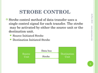
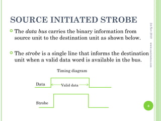
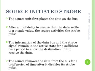
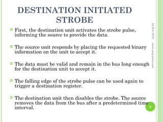
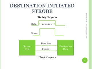
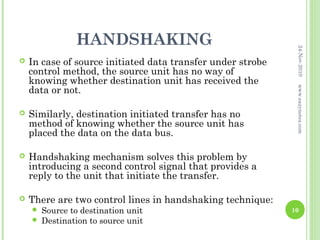

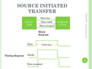
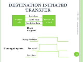
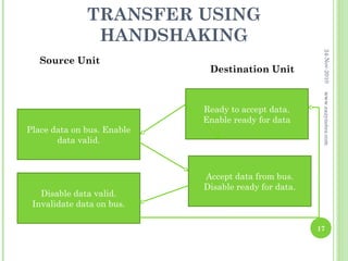


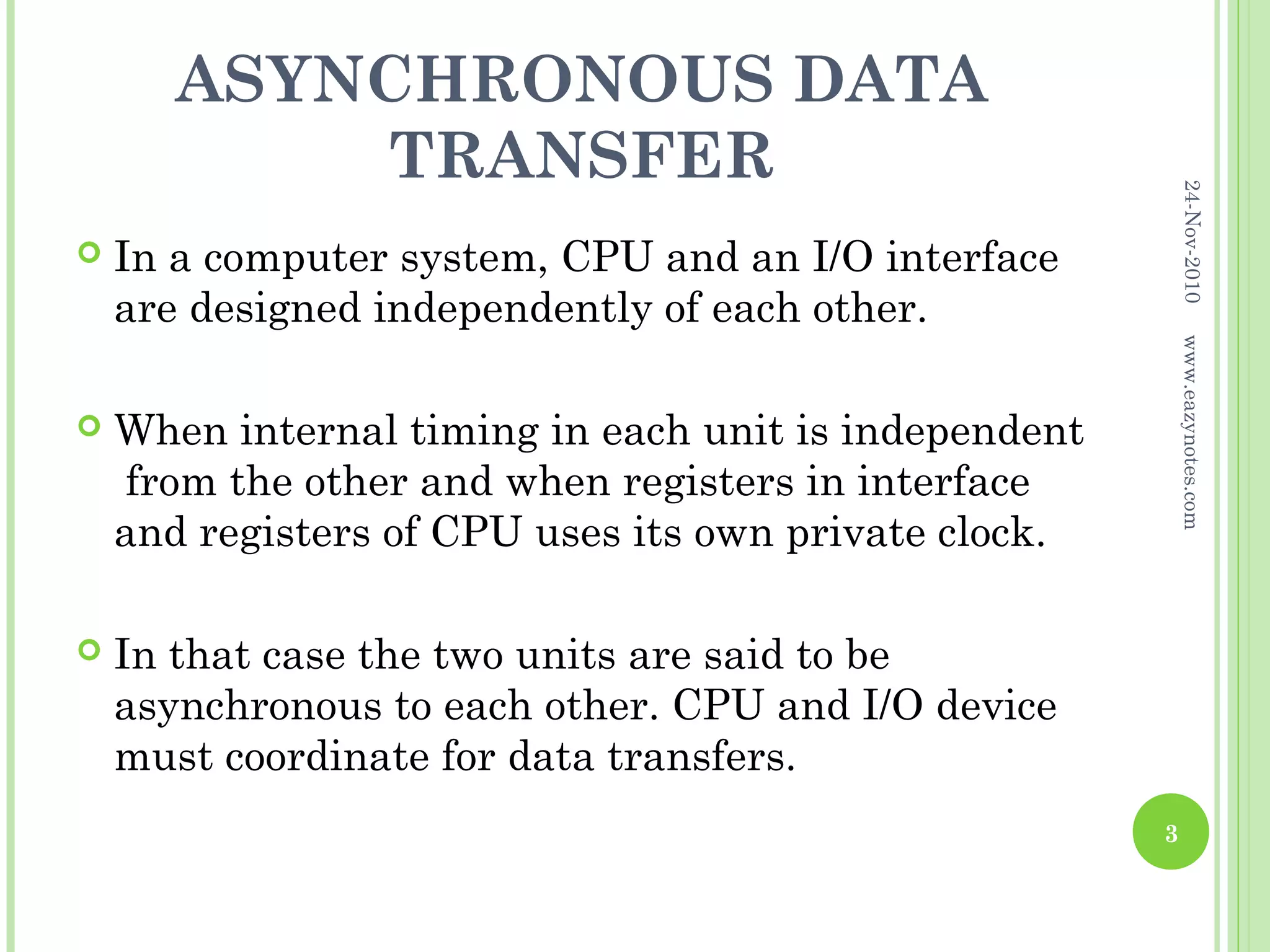
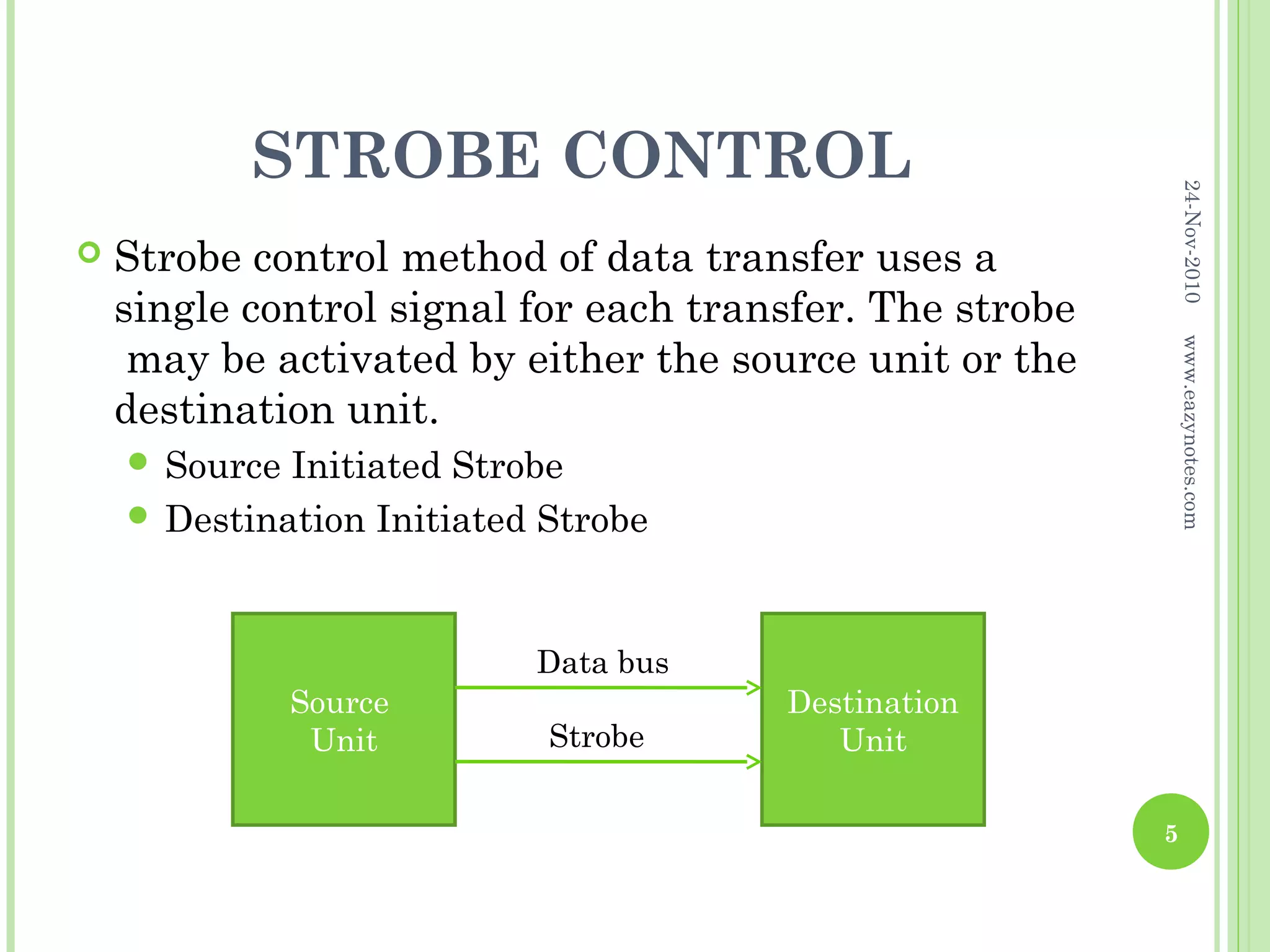
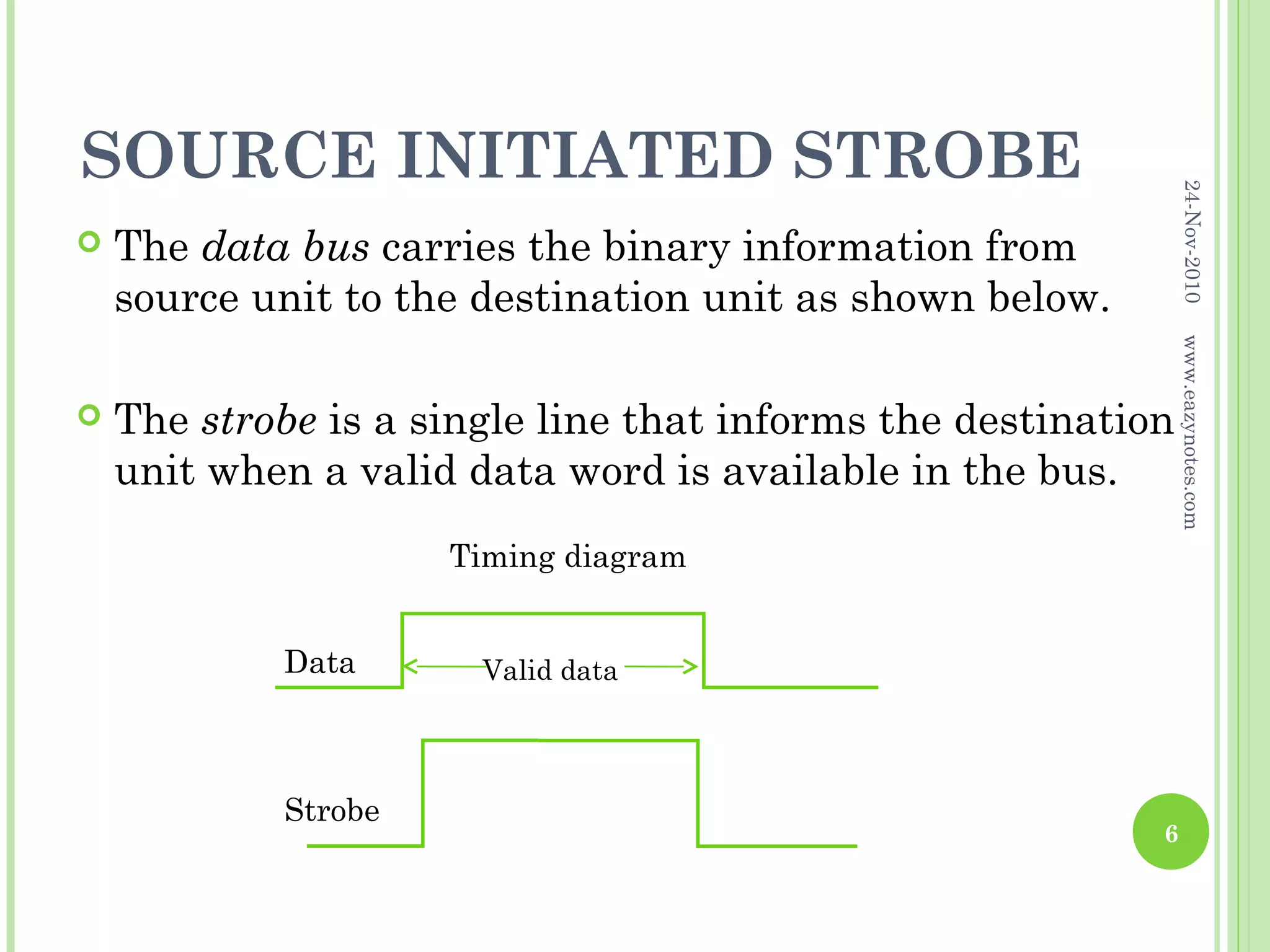
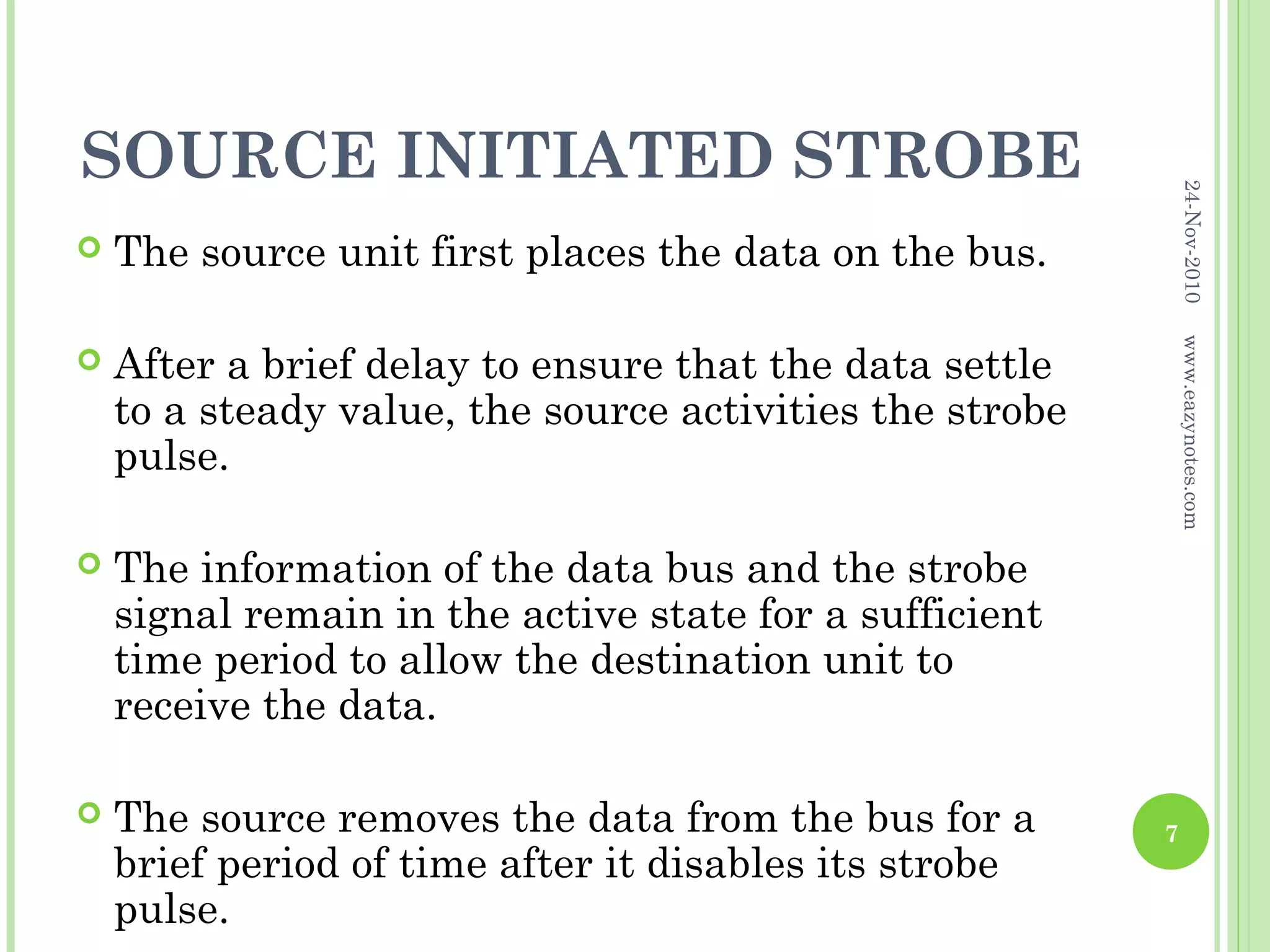

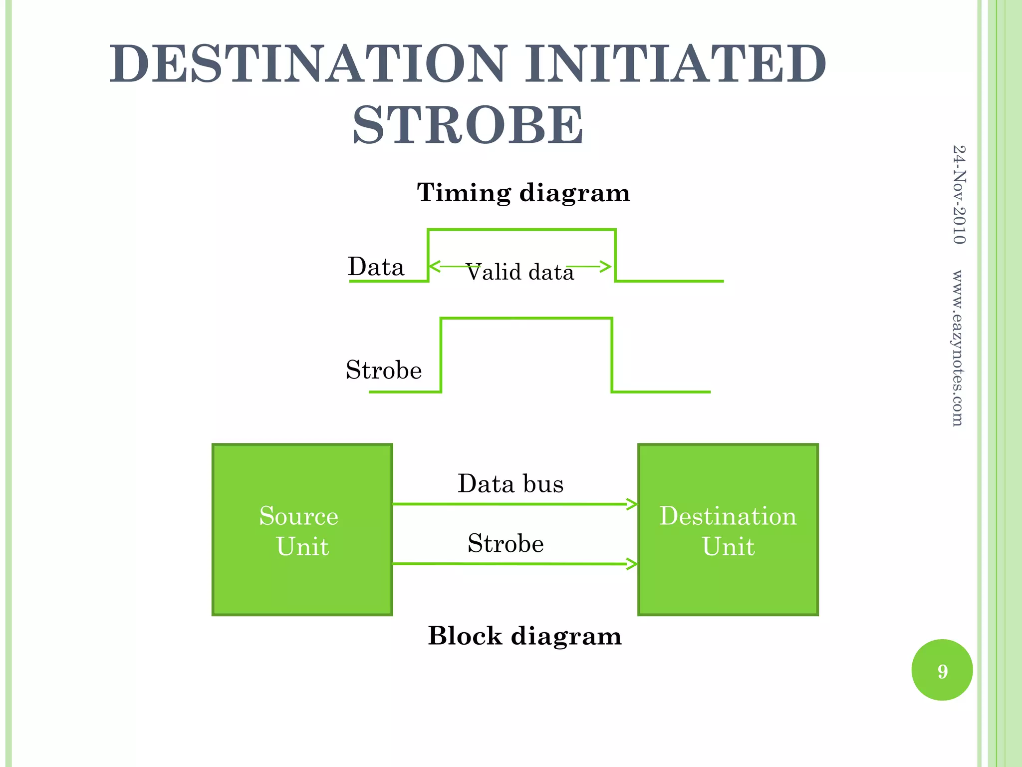
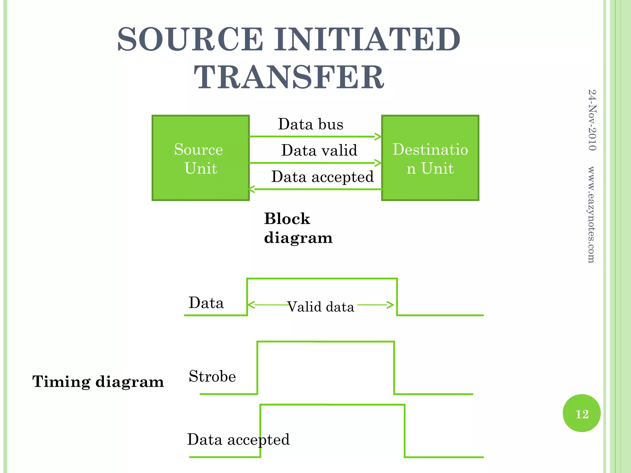

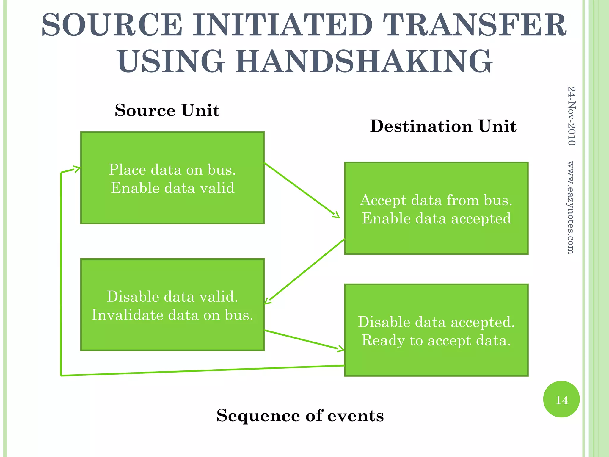
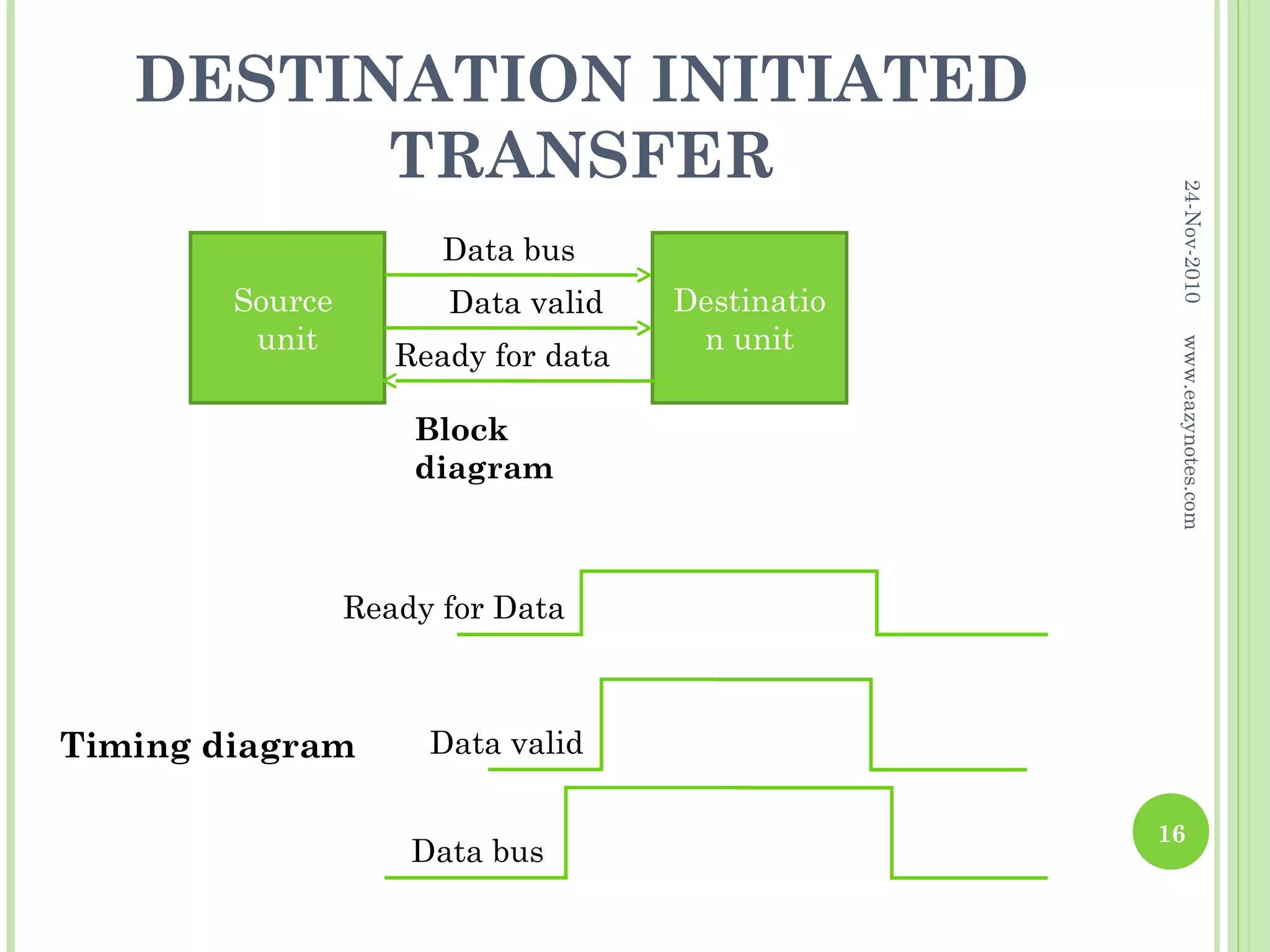
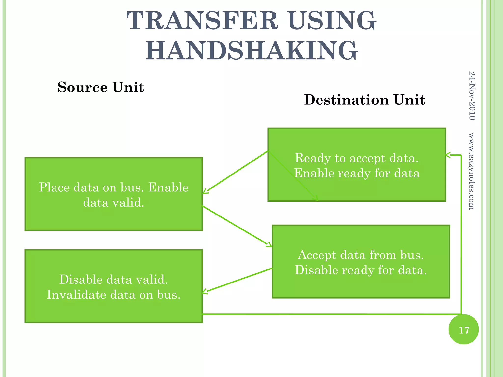


Synchronous data transfer involves sharing a common clock between a CPU and I/O interface so that data transfer is coordinated. Asynchronous transfer has independent clocks, so handshaking methods like strobe control and handshaking are used. Strobe control uses a single strobe pulse to indicate valid data. Handshaking adds a second control signal for acknowledgment between units. This ensures the source knows data was received and the destination knows data is available.


