Download as PPS, PPTX


An instruction format consists of bits that specify an operation to perform on data in computer memory. The processor fetches instructions from memory and decodes the bits to execute them. Instruction formats have operation codes to define operations like addition and an address field to specify where data is located. Computers may have different instruction sets.
Presentation on computer instructions by Maninder Kaur, highlighting the foundational context of computer operations.
Instruction formats define how computers execute operations and they comprise an instruction code which includes opcodes.
Instruction code consists of an operation code and address, detailing how operations like add or subtract are defined.
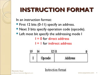
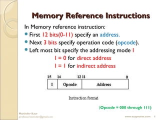
An instruction contains 12 address bits and 3 opcode bits, with addressing modes specified by the leftmost bit.
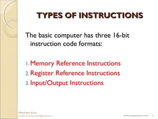
Defines the three basic 16-bit instruction code formats: Memory Reference, Register Reference, and Input/Output Instructions.
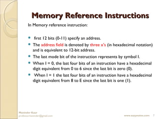
Memory reference instructions have 12 bits for addresses and specify an operation code and addressing mode.
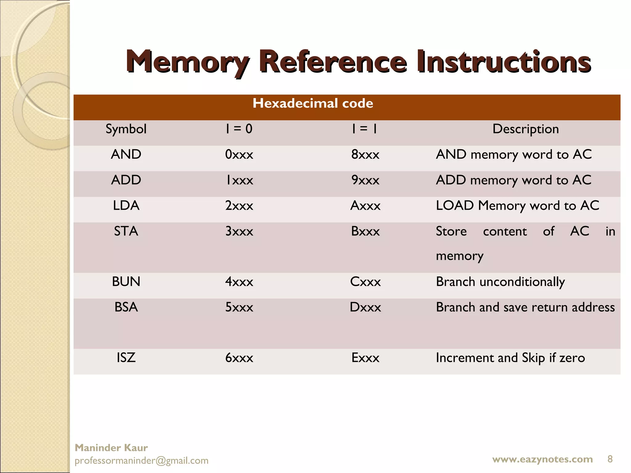
Explains how address fields are represented and defines the hexadecimal codes used in memory reference instructions.
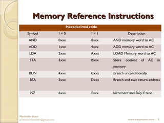
Shows the hexadecimal codes for memory operations like AND, ADD, LOAD, STORE, etc., and their representations.
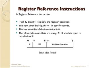
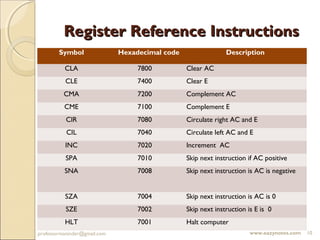
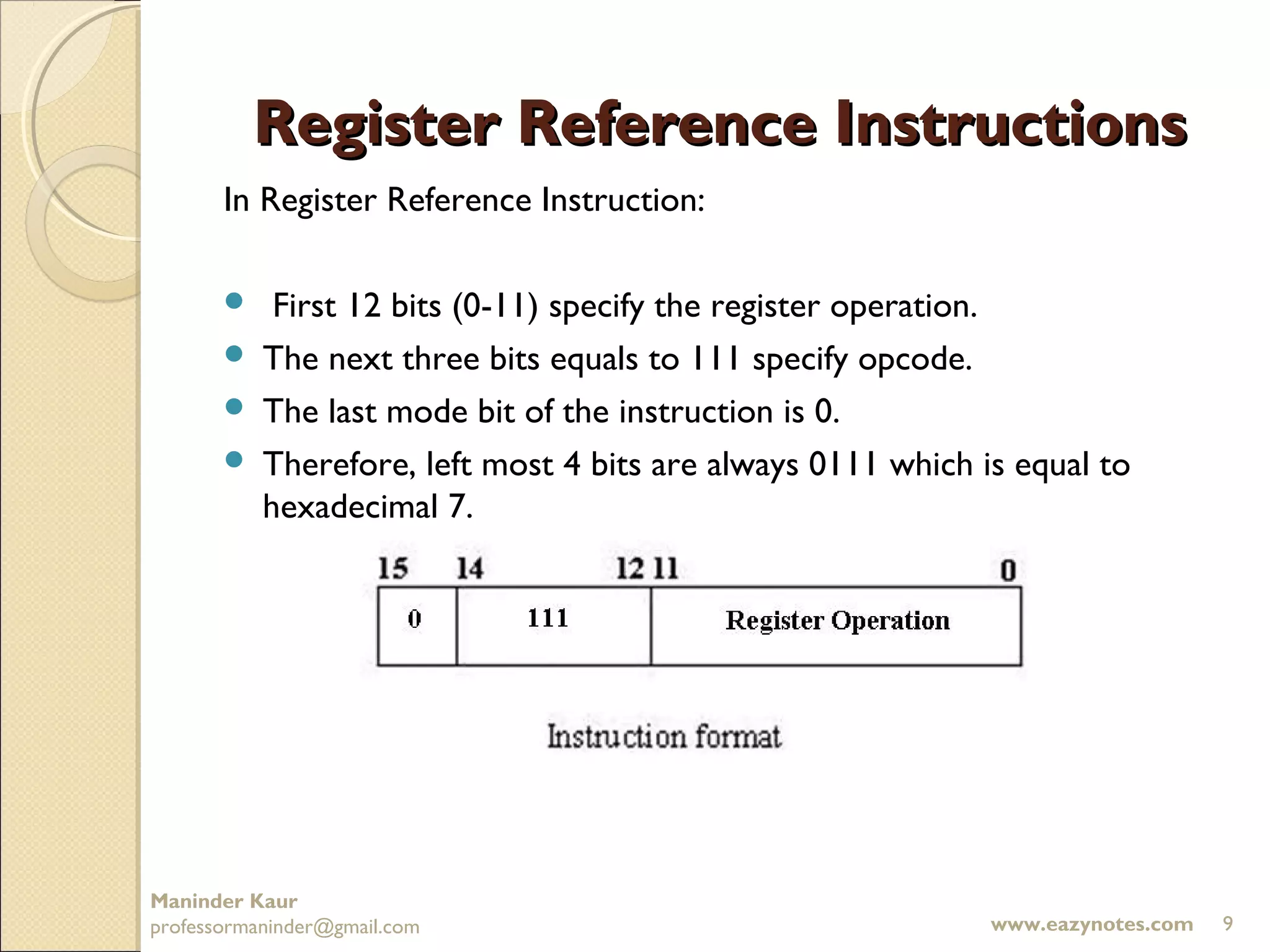
Explains how register reference instructions function with specific bits allocated for operation definitions.
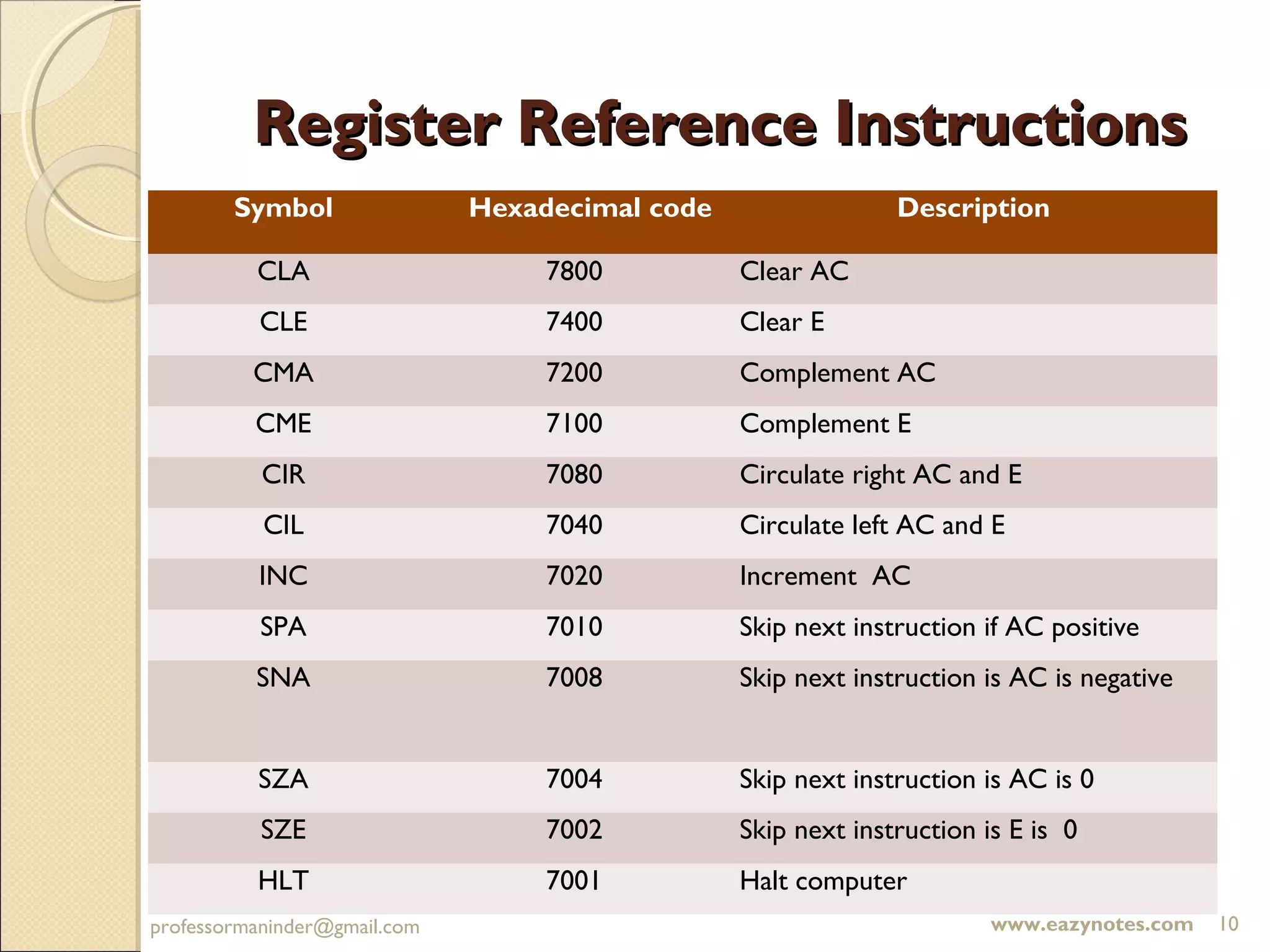
Details the action and hexadecimal codes associated with various register reference operations.
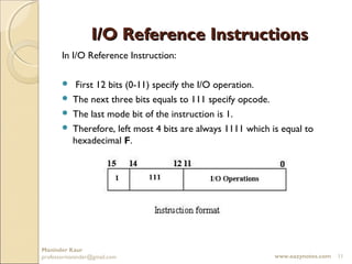
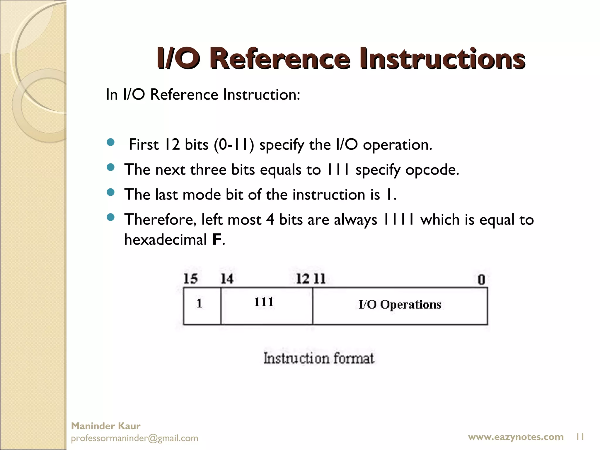
Describes the structure of I/O reference instructions that specify I/O operations and opcodes.
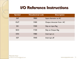
Provides hexadecimal codes for I/O operations such as input to AC, output from AC, and interrupt controls.


