Download to read offline
![2
Notes
Names in brackets, as in [Vaidya99], refer to a
document in the list of references
Many charts included in these slides are based on
similar results presented in graphs in published
literatures. Since, in many cases, exact numbers are
not provided in the papers, the charts in these slides
are based on “guess-timates” obtained from
published graphs. Please refer original sources for
accurate data.
This handout may not be as readable as the original
slides, since the slides contain colored text and
figures.](https://image.slidesharecdn.com/tcp-wireless-tutorial-220913150100-d90cc118/85/tcp-wireless-tutorial-ppt-2-320.jpg)

![4
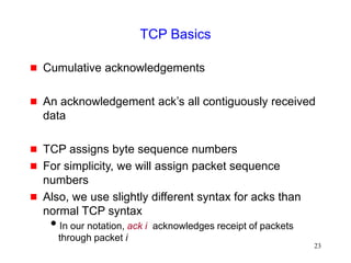
Internet Engineering Task Force (IETF)
Activities
IETF pilc (Performance Implications of Link
Characteristics) working group
http://www.ietf.org/html.charters/pilc-charter.html
http://pilc.grc.nasa.gov
Refer [Dawkins99] and [Montenegro99] for an overview of
related work
IETF tcpsat (TCP Over Satellite) working group
http://www.ietf.org/html.charters/tcpsat-charter.html
http://tcpsat.grc.nasa.gov/tcpsat/
Refer [Allman98] for overview of satellite related work](https://image.slidesharecdn.com/tcp-wireless-tutorial-220913150100-d90cc118/85/tcp-wireless-tutorial-ppt-4-320.jpg)


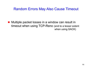
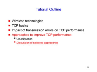
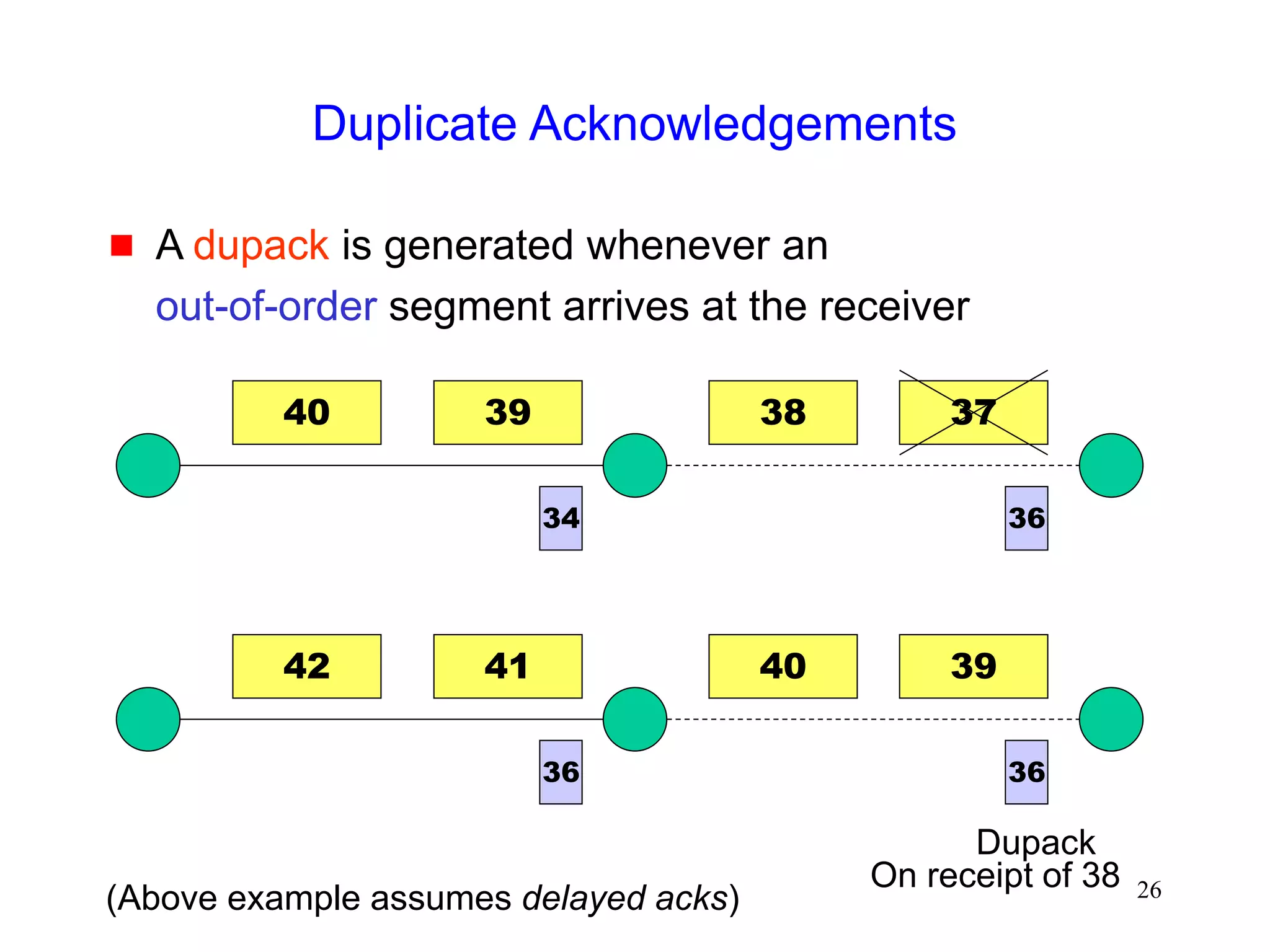
![51
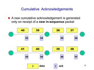
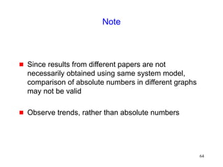
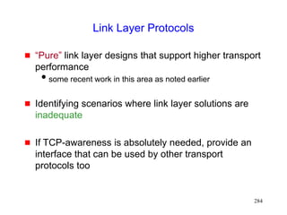
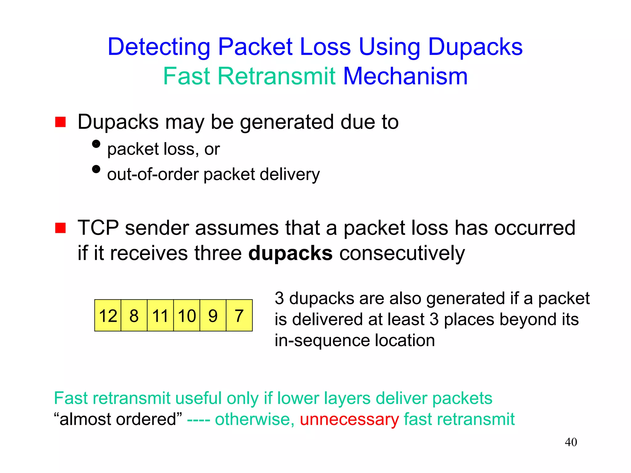
Fast Recovery
Fast recovery can result in a timeout with multiple
losses per RTT
.
TCP New-Reno [Hoe96]
stay in fast recovery until all packet losses in window are
recovered
can recover 1 packet loss per RTT without
causing a timeout
Selective Acknowledgements (SACK)
[mathis96rfc2018]
provides information about out-of-order packets received by
receiver
can recover multiple packet losses per RTT](https://image.slidesharecdn.com/tcp-wireless-tutorial-220913150100-d90cc118/85/tcp-wireless-tutorial-ppt-51-320.jpg)
![61
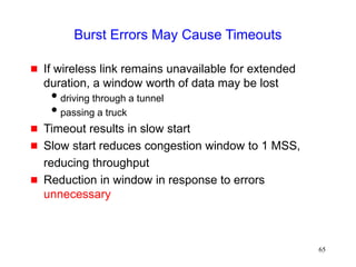
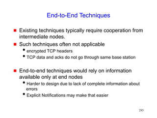
Sometimes Congestion Response May be
Appropriate in Response to Errors
On a CDMA channel, errors occur due to interference
from other user, and due to noise [Karn99pilc]
Interference due to other users is an indication of
congestion. If such interference causes transmission errors,
it is appropriate to reduce congestion window
If noise causes errors, it is not appropriate to reduce window
When a channel is in a bad state for a long duration,
it might be better to let TCP backoff, so that it does
not unnecessarily attempt retransmissions while the
channel remains in the bad state
[Padmanabhan99pilc]](https://image.slidesharecdn.com/tcp-wireless-tutorial-220913150100-d90cc118/85/tcp-wireless-tutorial-ppt-61-320.jpg)
![63
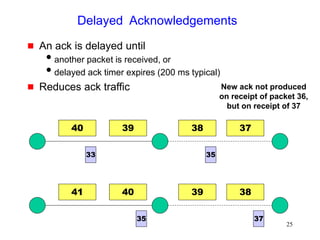
Impact of Random Errors [Vaidya99]
0
400000
800000
1200000
1600000
16384 32768 65536 131072
1/error rate (in bytes)
bits/sec
Exponential error model
2 Mbps wireless full duplex link
No congestion losses](https://image.slidesharecdn.com/tcp-wireless-tutorial-220913150100-d90cc118/85/tcp-wireless-tutorial-ppt-63-320.jpg)

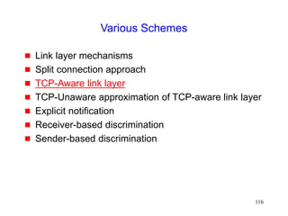
![76
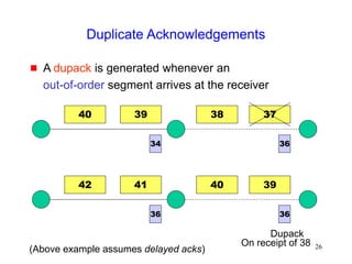
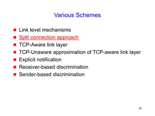
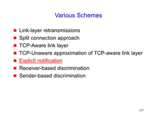
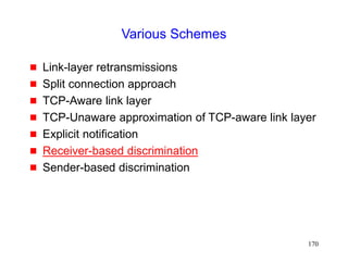
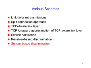
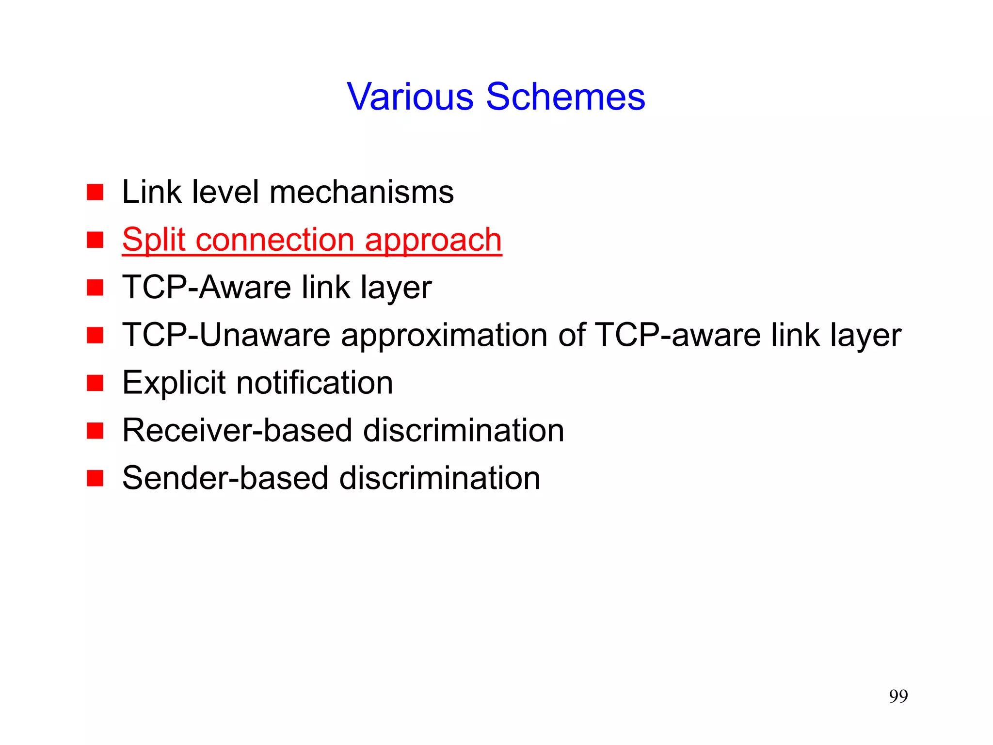
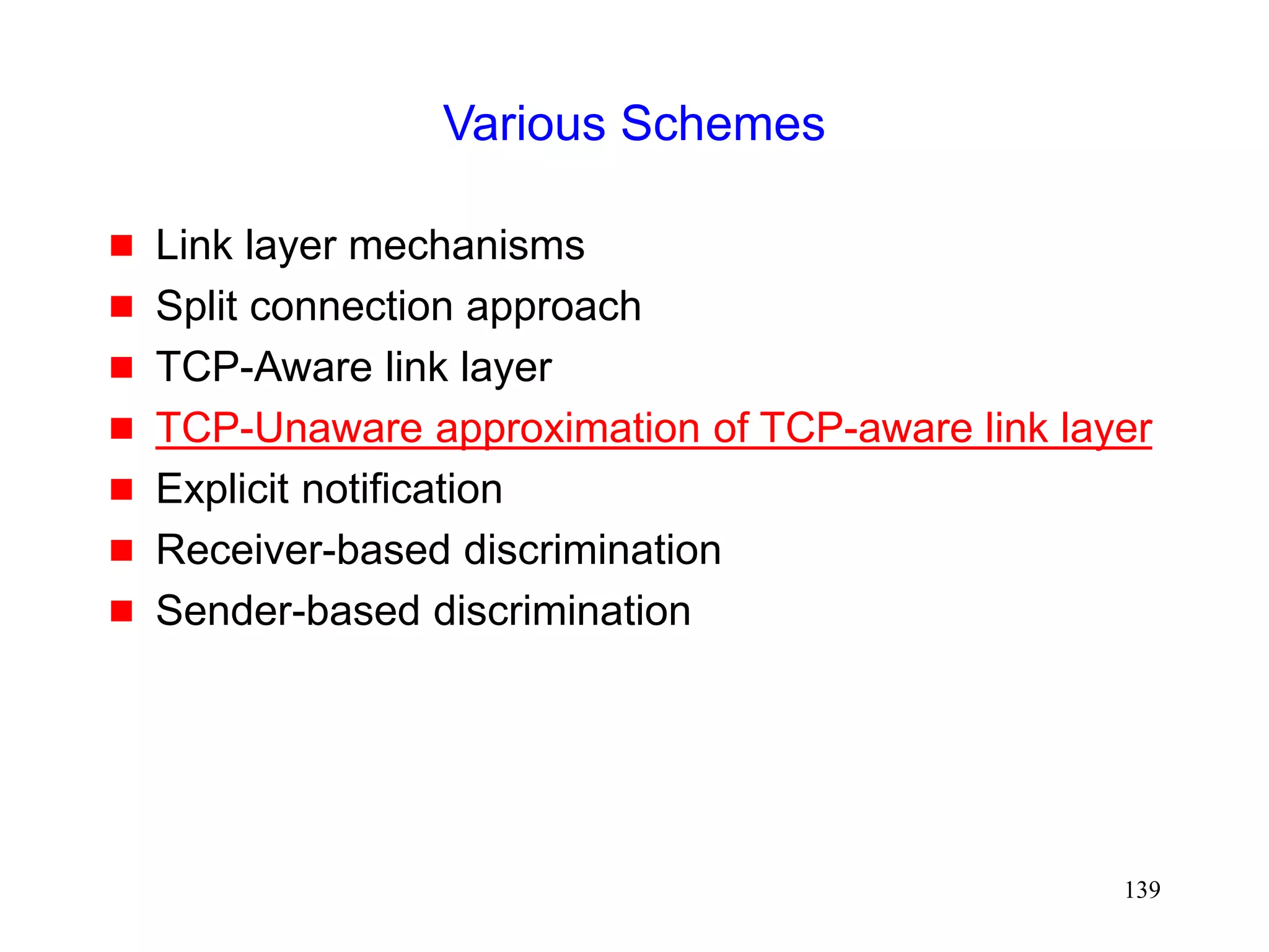
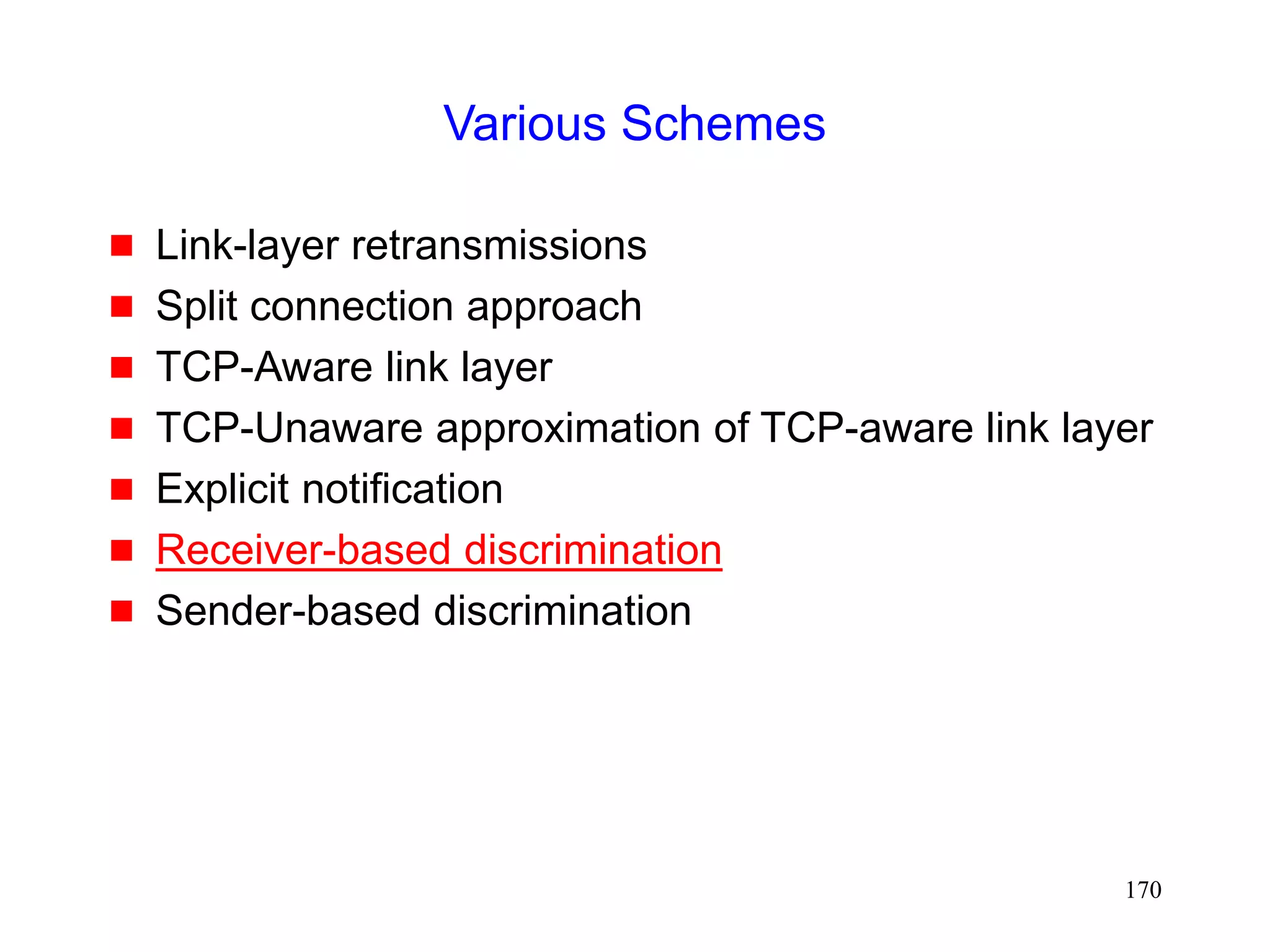
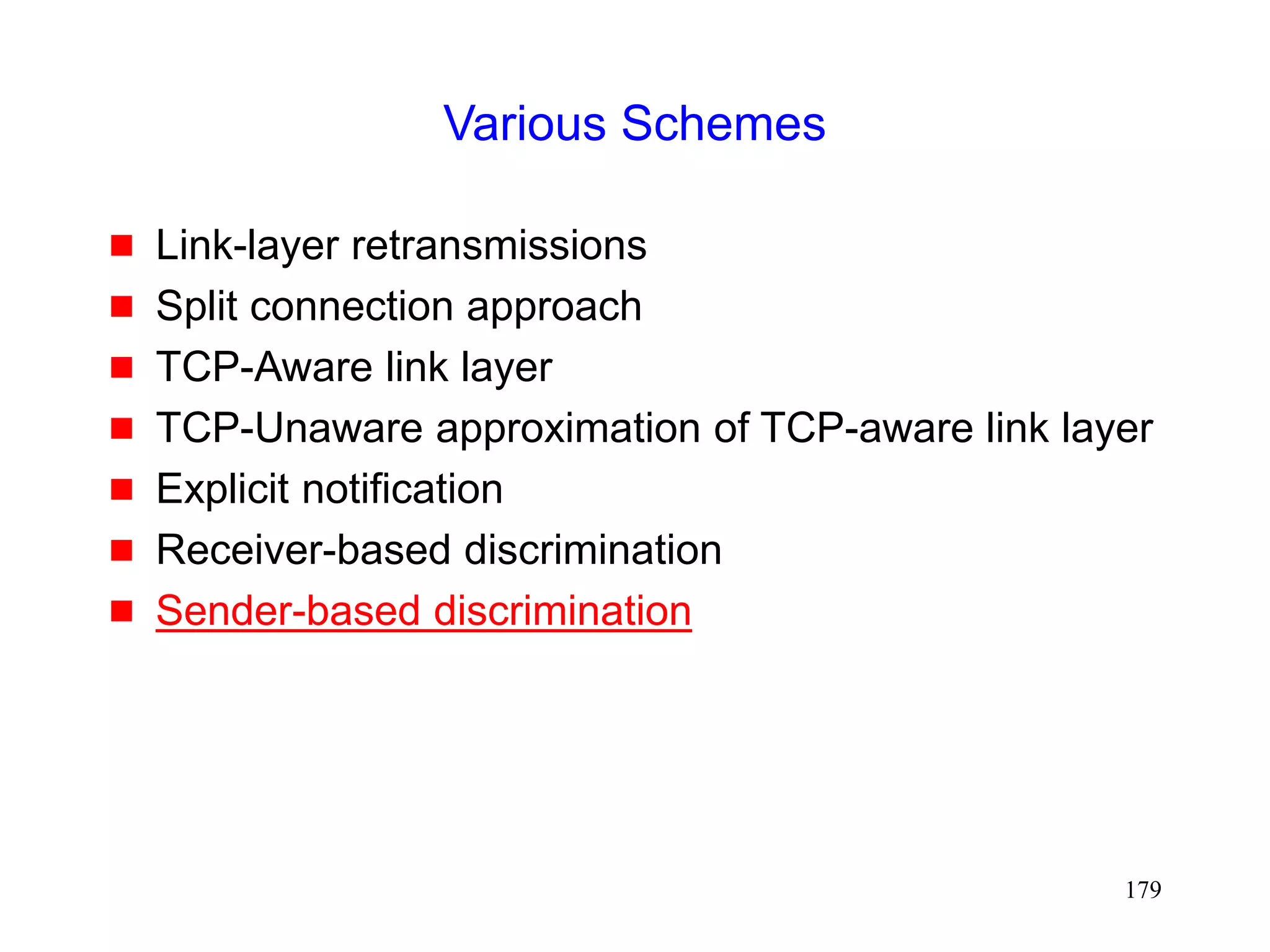
Various Schemes
Link level mechanisms
Split connection approach
TCP-Aware link layer
TCP-Unaware approximation of TCP-aware link layer
Explicit notification
Receiver-based discrimination
Sender-based discrimination
For a brief overview, see [Dawkins99,Montenegro99]](https://image.slidesharecdn.com/tcp-wireless-tutorial-220913150100-d90cc118/85/tcp-wireless-tutorial-ppt-76-320.jpg)
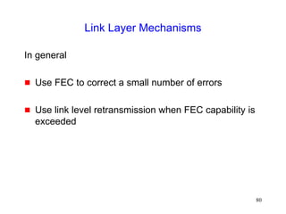
![78
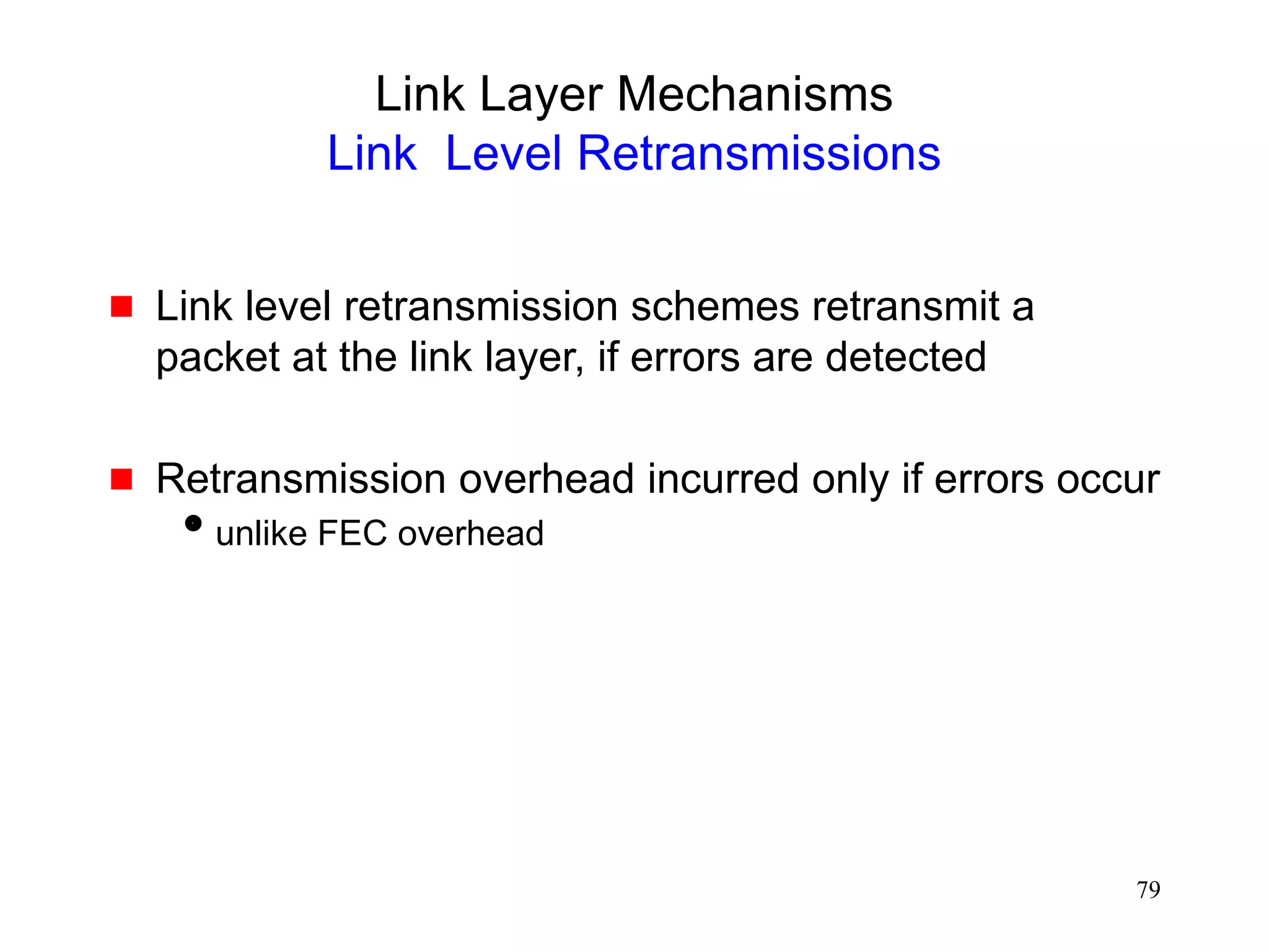
Link Layer Mechanisms
Forward Error Correction
Forward Error Correction (FEC) [Lin83] can be use
to correct small number of errors
Correctable errors hidden from the TCP sender
FEC incurs overhead even when errors do not occur
Adaptive FEC schemes [Eckhardt98] can reduce the
overhead by choosing appropriate FEC dynamically](https://image.slidesharecdn.com/tcp-wireless-tutorial-220913150100-d90cc118/85/tcp-wireless-tutorial-ppt-78-320.jpg)
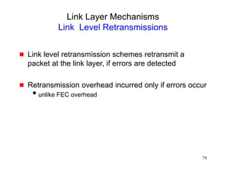
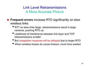
![86
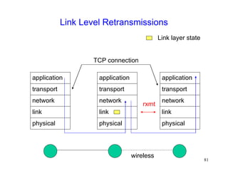
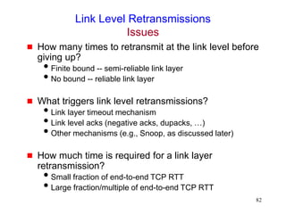
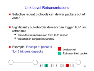
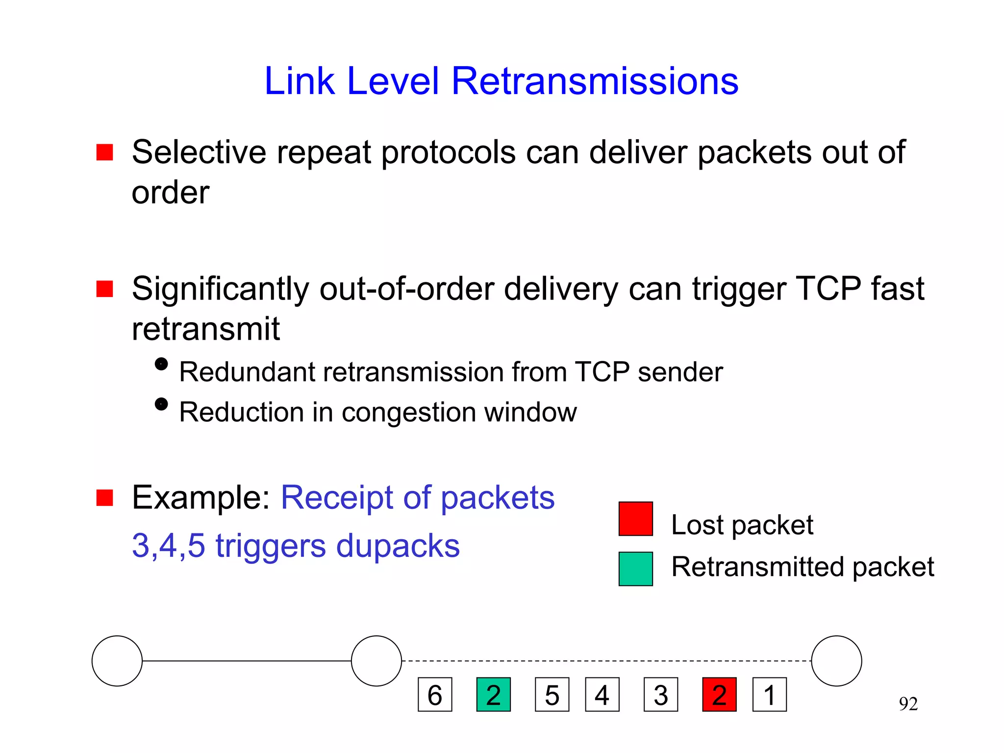
Link Level Retransmissions
An Early Study [DeSimone93]
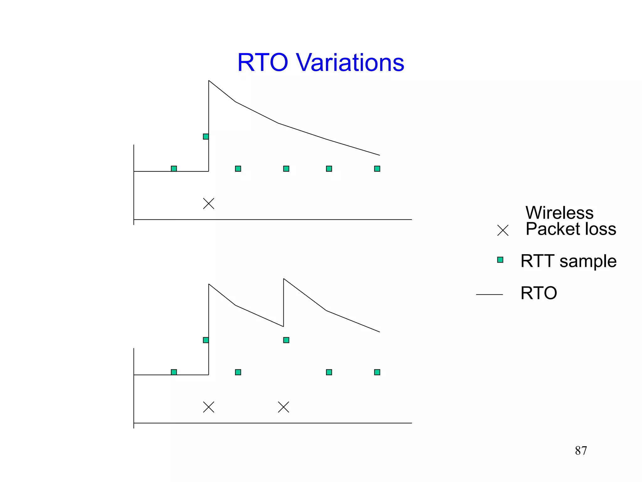
The sender’s Retransmission Timeout (RTO) is a
function of measured RTT (round-trip times)
Link level retransmits increase RTT, therefore, RTO
If errors not frequent, RTO will not account for RTT
variations due to link level retransmissions
When errors occur, the sender may timeout & retransmit
before link level retransmission is successful
Sender and link layer both retransmit
Duplicate retransmissions (interference) waste wireless
bandwidth
Timeouts also result in reduced congestion window](https://image.slidesharecdn.com/tcp-wireless-tutorial-220913150100-d90cc118/85/tcp-wireless-tutorial-ppt-86-320.jpg)
![88
A More Accurate Picture
Analysis in [DeSimone93] does not accurately model
real TCP stacks
With large RTO granularity, interference is unlikely, if
time required for link-level retransmission is small
compared to TCP RTO [Balakrishnan96Sigcomm]
Standard TCP RTO granularity is often large
Minimum RTO (2*granularity) is large enough to allow a
small number of link level retransmissions, if link level RTT is
relatively small
Interference due to timeout not a significant issue when
wireless RTT small, and RTO granularity large [Eckhardt98]](https://image.slidesharecdn.com/tcp-wireless-tutorial-220913150100-d90cc118/85/tcp-wireless-tutorial-ppt-88-320.jpg)
![90
Link-Layer Retransmissions
A More Accurate Picture [Ludwig98]
Timeout interval may actually be larger than RTO
Retransmission timer reset on an ack
If the ack’d packet and next packet were transmitted in a
burst, next packet gets an additional RTT before the timer
will go off
1 2
data ack
Timeout = RTO
Effectively, Timeout = RTT of packet 1 + RTO
Reset, Timeout = RTO](https://image.slidesharecdn.com/tcp-wireless-tutorial-220913150100-d90cc118/85/tcp-wireless-tutorial-ppt-90-320.jpg)
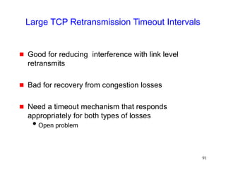
![94
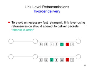
Link Level Retransmissions
In-order delivery
Not all connections benefit from retransmissions or
ordered delivery
audio
Need to be able to specify requirements on a per-
packet basis [Ludwig99]
Should the packet be retransmitted? How many times?
Enforce in-order delivery?
Need a standard mechanism to specify the
requirements
open issue (IETF PILC working group)](https://image.slidesharecdn.com/tcp-wireless-tutorial-220913150100-d90cc118/85/tcp-wireless-tutorial-ppt-94-320.jpg)
![95
Adaptive Link Layer Strategies
[Lettieri98,Eckhardt98,Zorzi97]
Adaptive protocols attempt to dynamically choose:
FEC code
retransmission limit
frame size](https://image.slidesharecdn.com/tcp-wireless-tutorial-220913150100-d90cc118/85/tcp-wireless-tutorial-ppt-95-320.jpg)
![96
Link Layer Retransmissions [Vaidya99]
0
400000
800000
1200000
1600000
2000000
16384
32768
65536
1E+05
1/error rate (in bytes)
base TCP
Link layer
retransmission
2 Mbps wireless duplex link with 1 ms delay
Exponential error model
No congestion losses
20 ms 1 ms
10 Mbps 2 Mbps](https://image.slidesharecdn.com/tcp-wireless-tutorial-220913150100-d90cc118/85/tcp-wireless-tutorial-ppt-96-320.jpg)

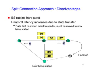
![105
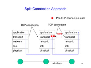
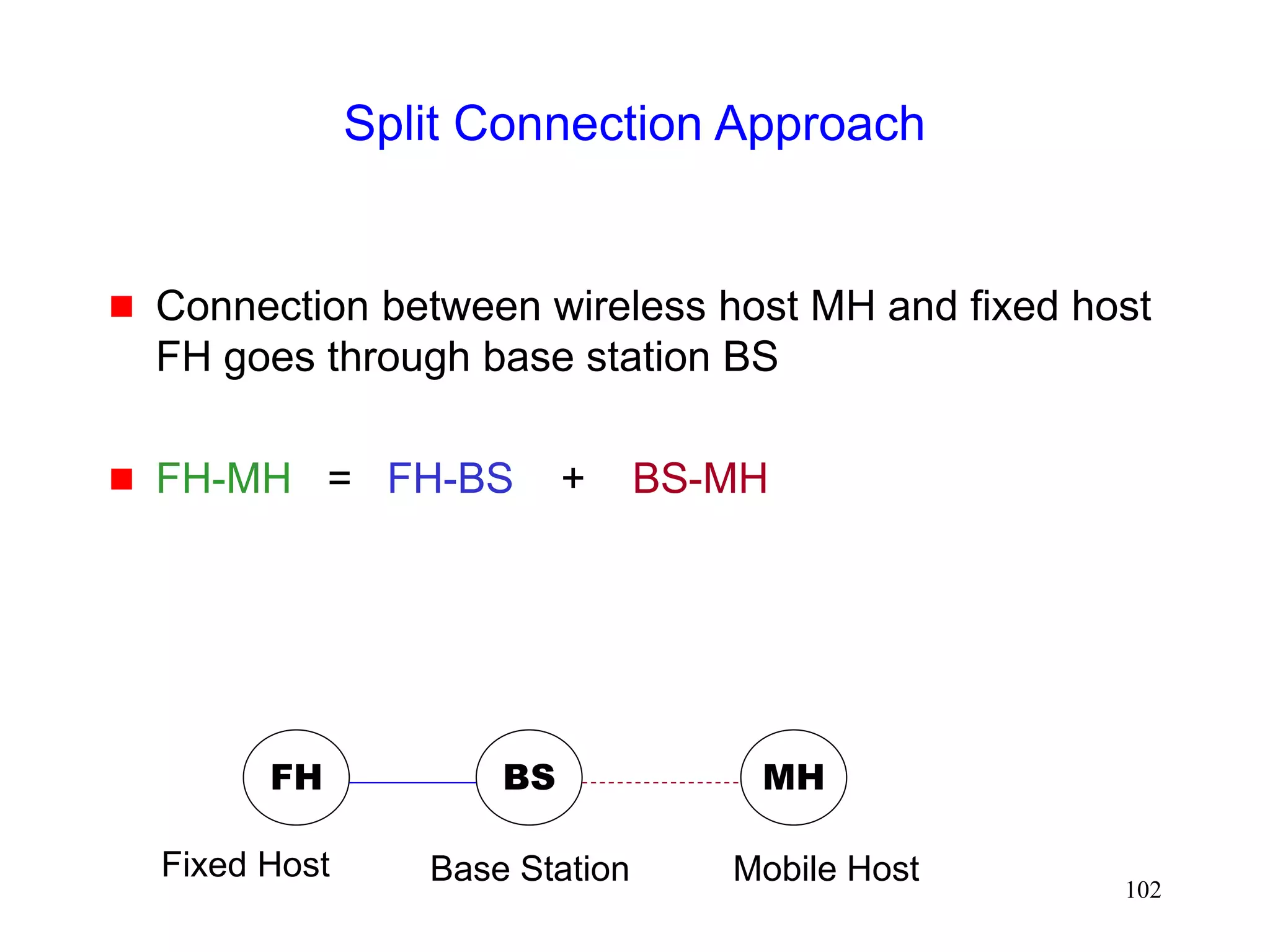
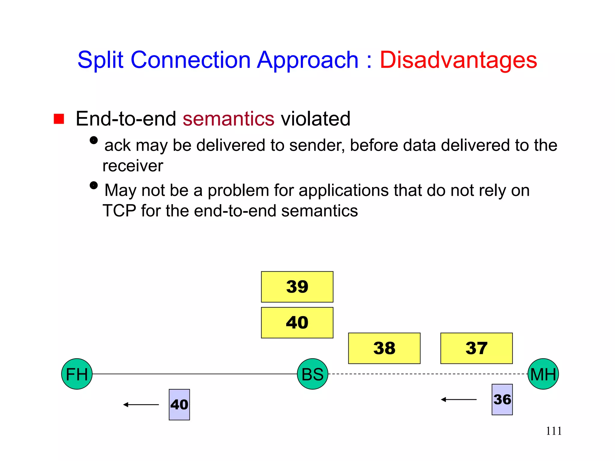
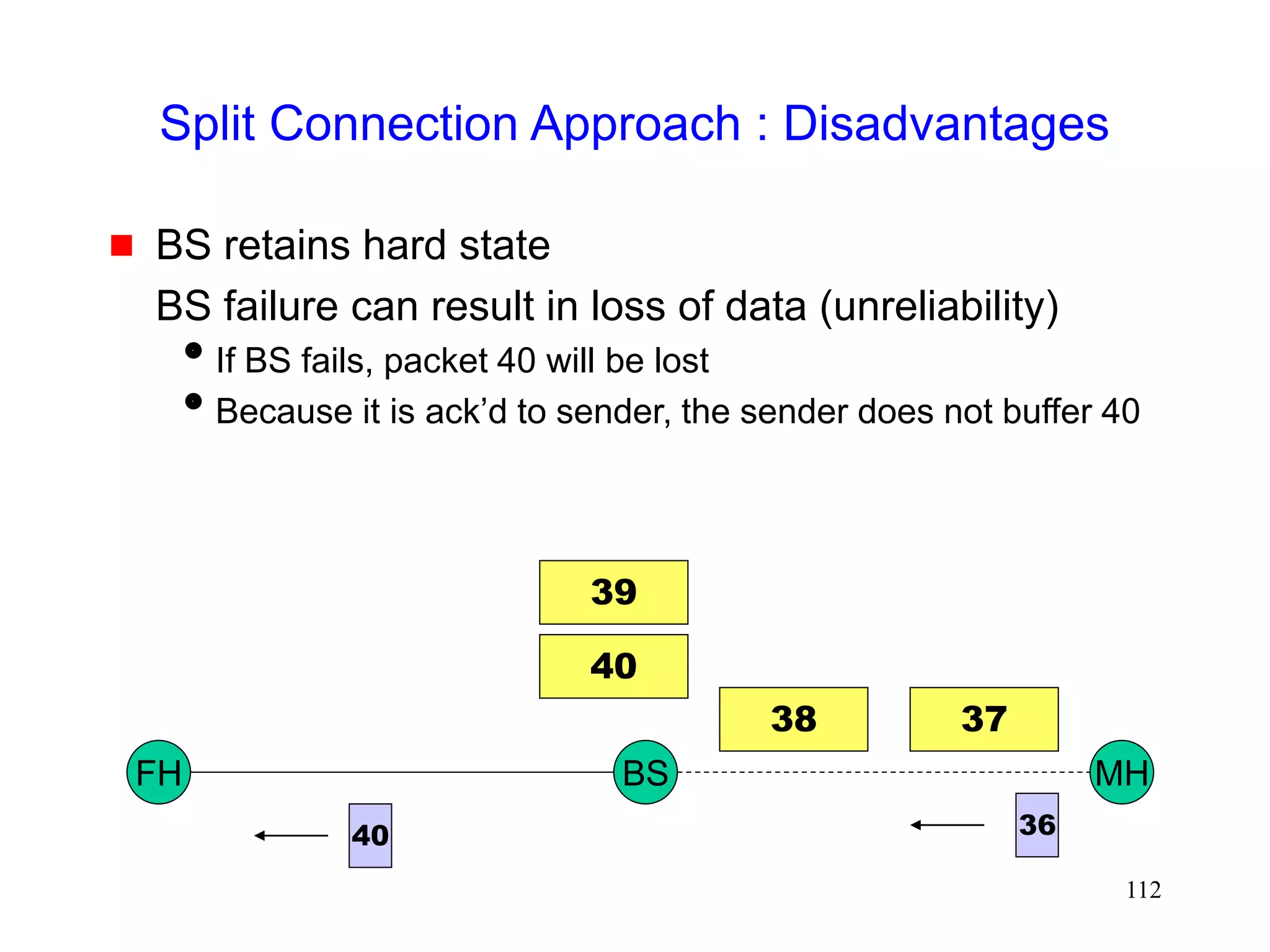
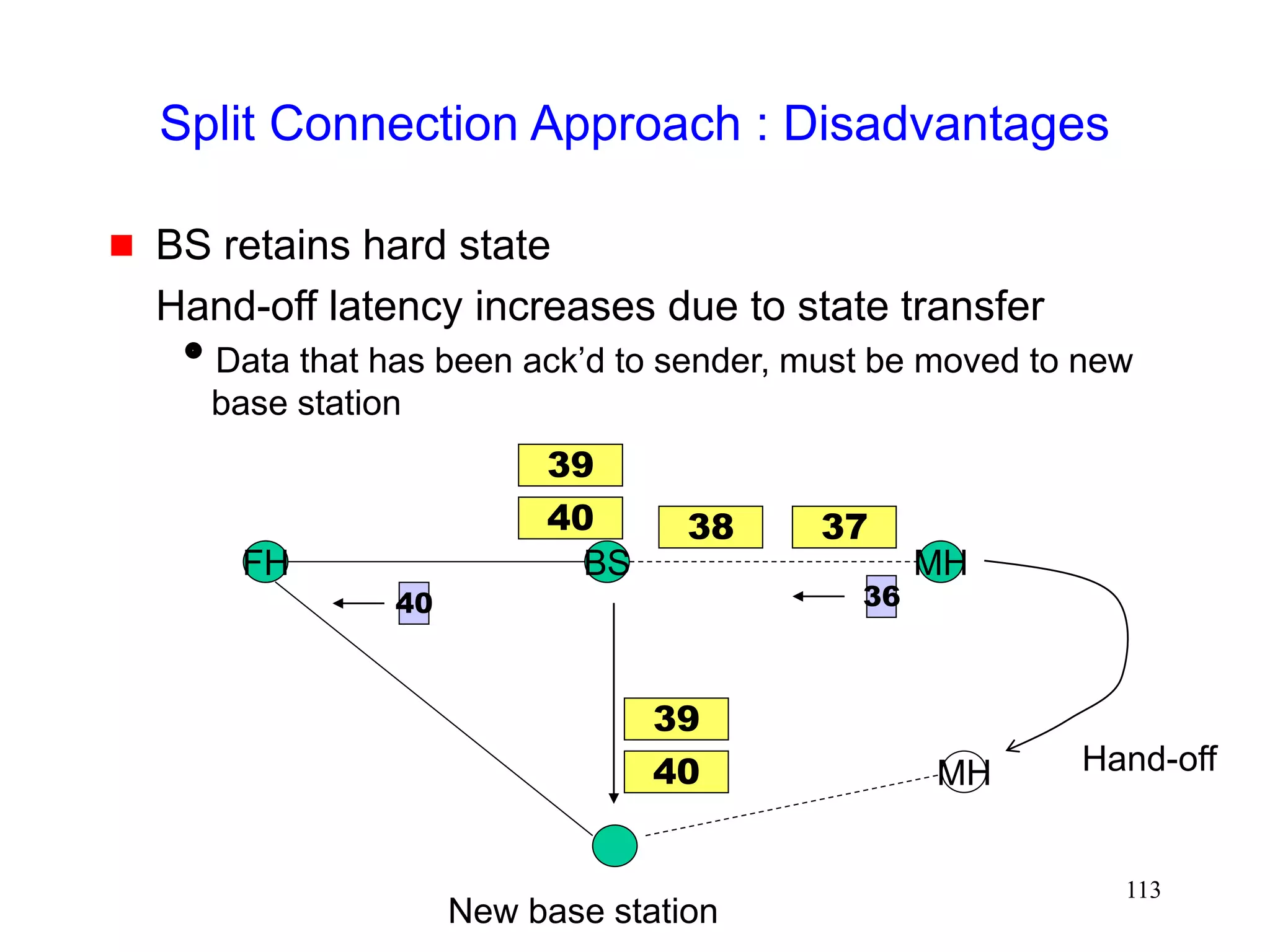
Split Connection Approach
Indirect TCP [Bakre95,Bakre97]
FH - BS connection : Standard TCP
BS - MH connection : Standard TCP](https://image.slidesharecdn.com/tcp-wireless-tutorial-220913150100-d90cc118/85/tcp-wireless-tutorial-ppt-105-320.jpg)
![106
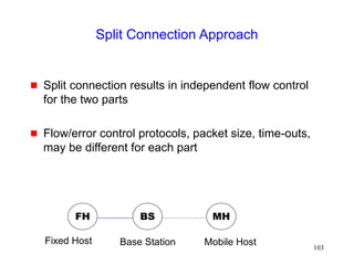
Split Connection Approach
Selective Repeat Protocol (SRP) [Yavatkar94]
FH - BS connection : standard TCP
BS - FH connection : selective repeat protocol on top
of UDP
Performance better than Indirect-TCP (I-TCP),
because wireless portion of the connection can be
tuned to wireless behavior](https://image.slidesharecdn.com/tcp-wireless-tutorial-220913150100-d90cc118/85/tcp-wireless-tutorial-ppt-106-320.jpg)
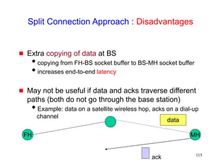
![107
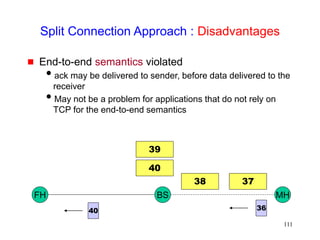
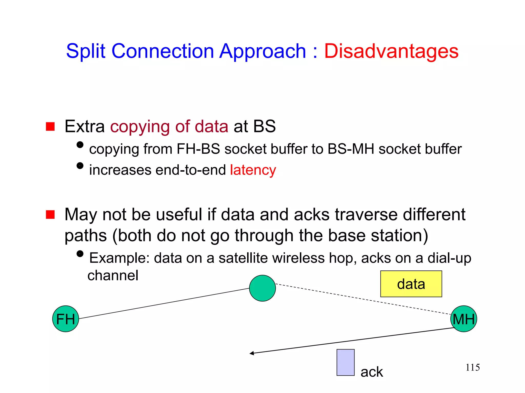
Split Connection Approach : Other Variations
Asymmetric transport protocol (Mobile-TCP)
[Haas97icc]
Low overhead protocol at wireless hosts, and higher
overhead protocol at wired hosts
smaller headers used on wireless hop (header compression)
simpler flow control - on/off for MH to BS transfer
MH only does error detection, BS does error correction too
No congestion control over wireless hop](https://image.slidesharecdn.com/tcp-wireless-tutorial-220913150100-d90cc118/85/tcp-wireless-tutorial-ppt-107-320.jpg)
![108
Split Connection Approach : Other Variations
Mobile-End Transport Protocol [Wang98infocom]
Terminate the TCP connection at BS
TCP connection runs only between BS and FH
BS pretends to be MH (MH’s IP functionality moved
to BS)
BS guarantees reliable ordered delivery of packets to
MH
BS-MH link can use any arbitrary protocol optimized
for wireless link
Idea similar to [Yavatkar94]](https://image.slidesharecdn.com/tcp-wireless-tutorial-220913150100-d90cc118/85/tcp-wireless-tutorial-ppt-108-320.jpg)

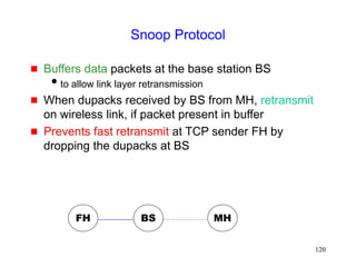
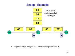
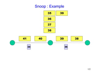
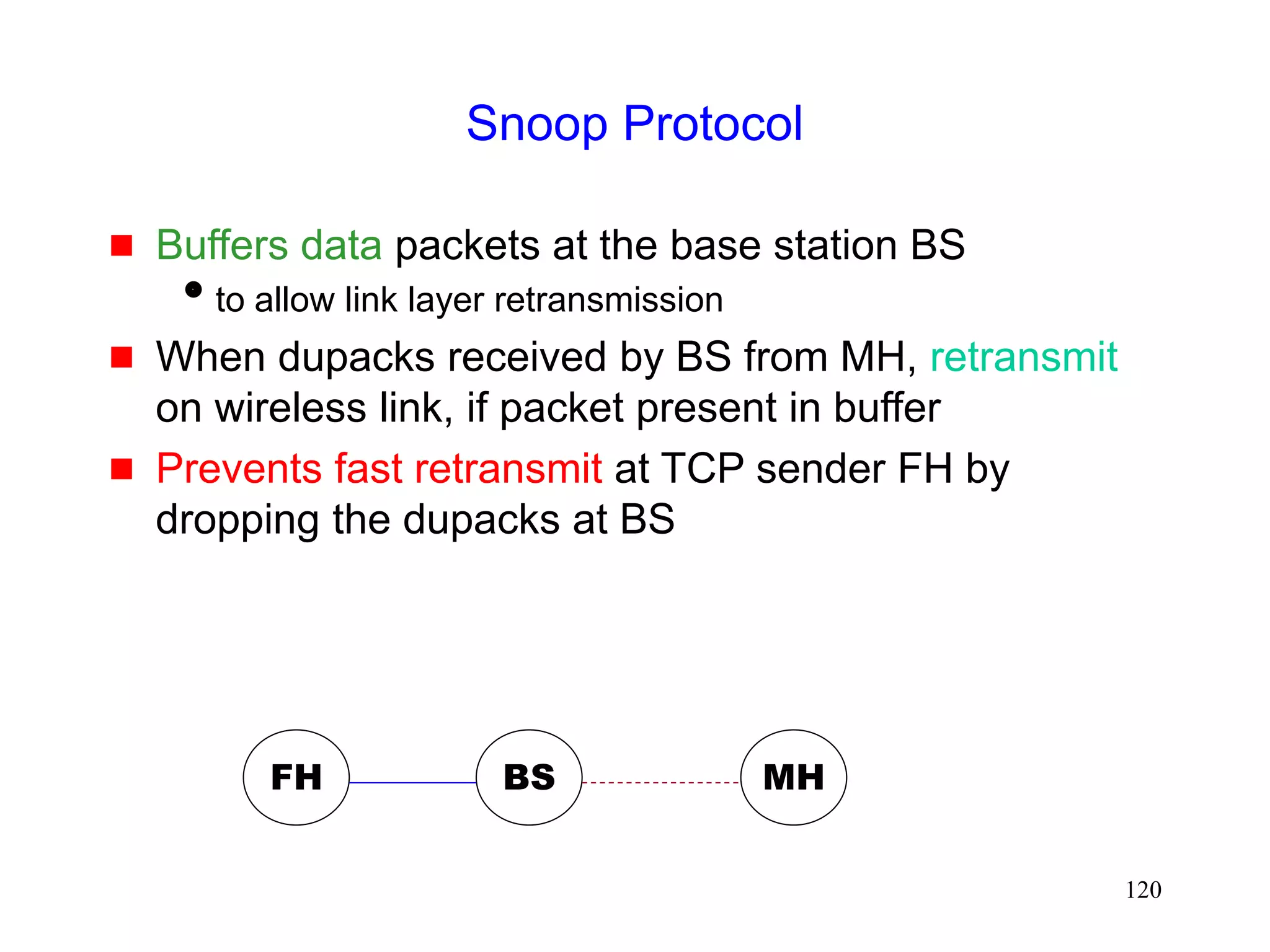
![118
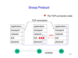
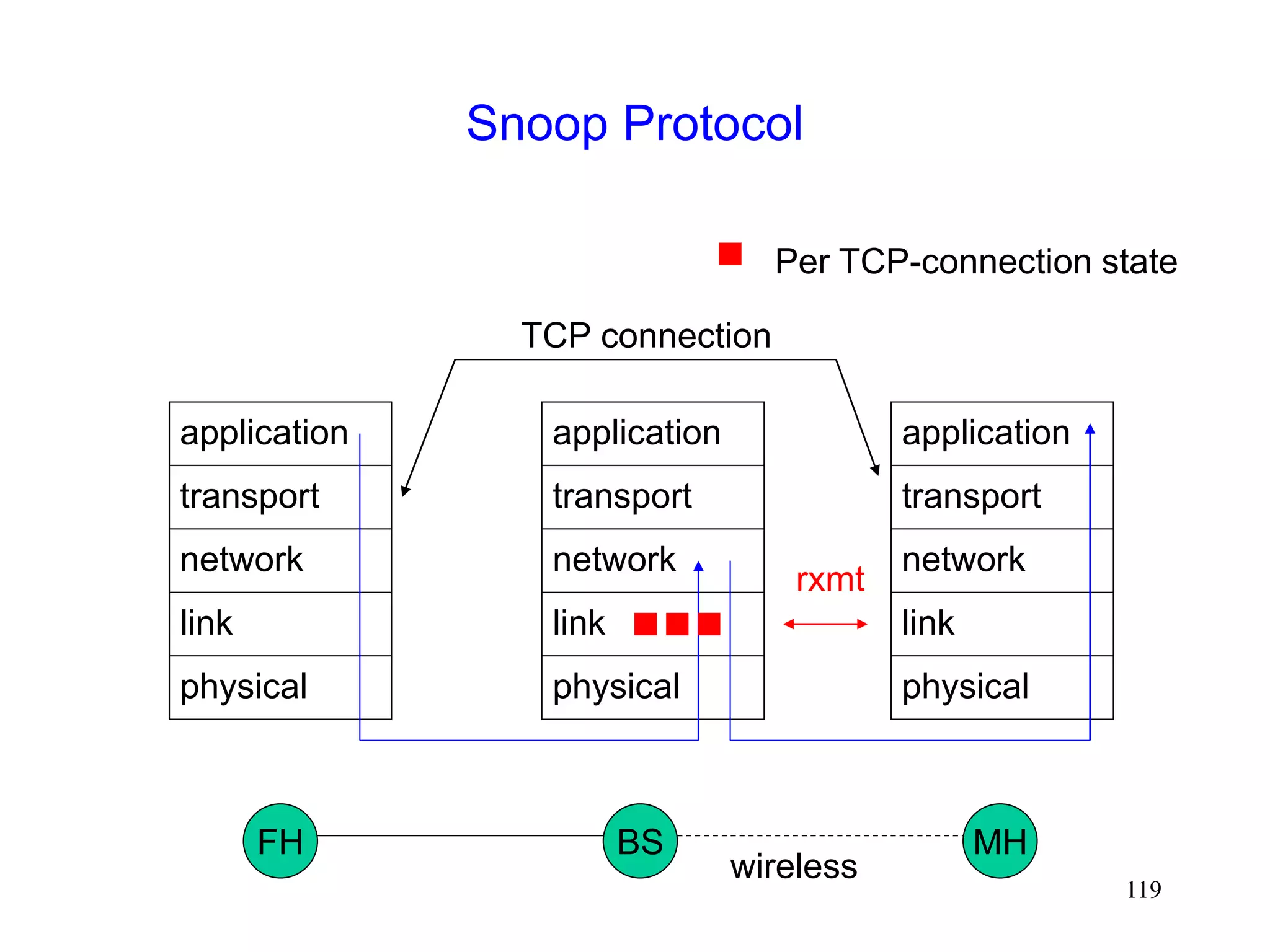
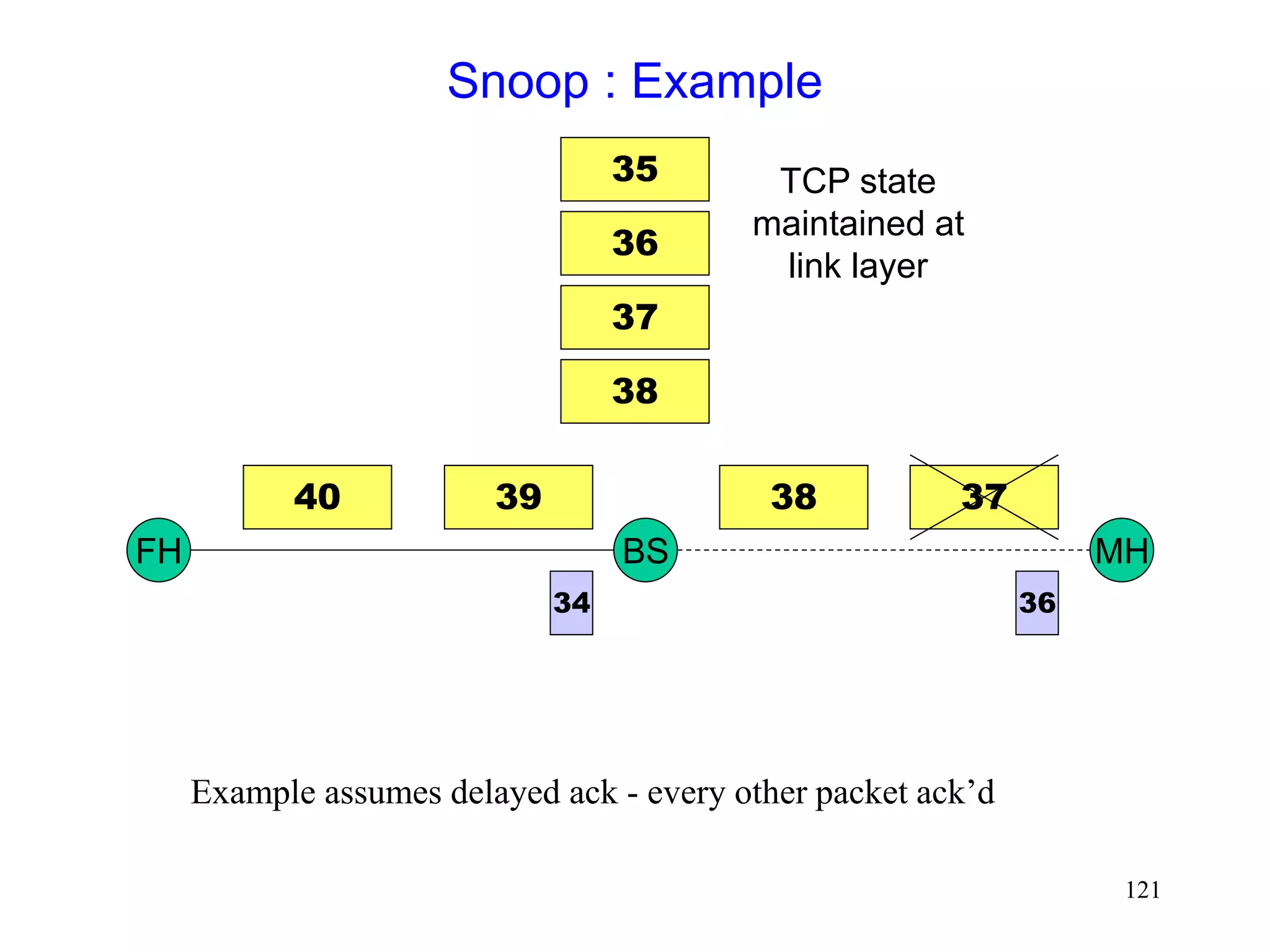
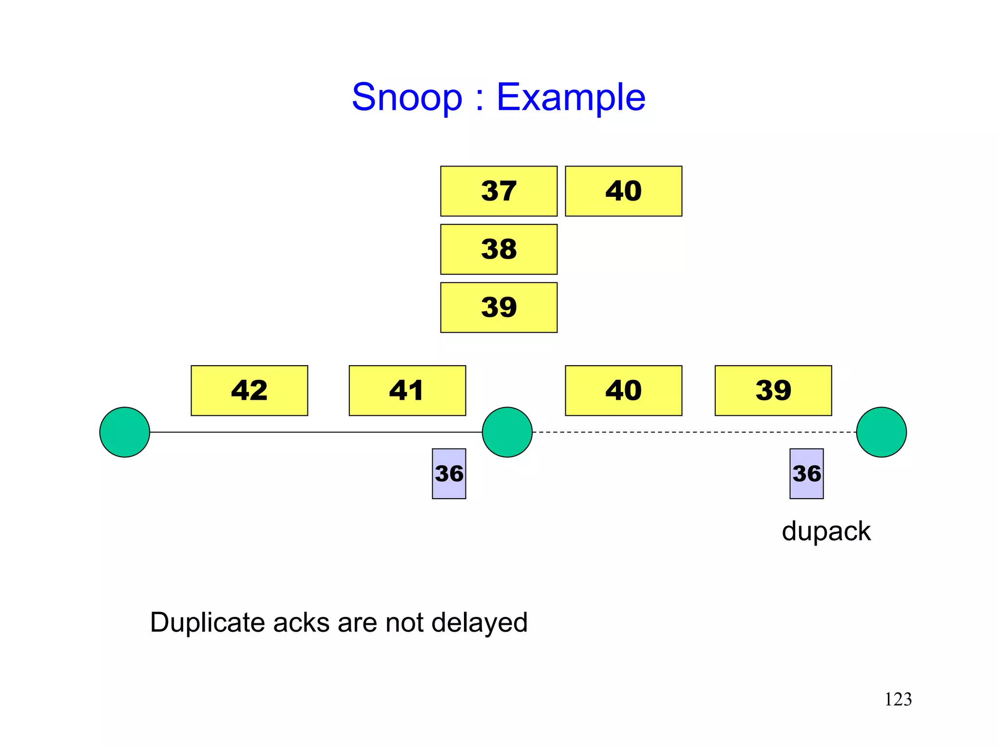
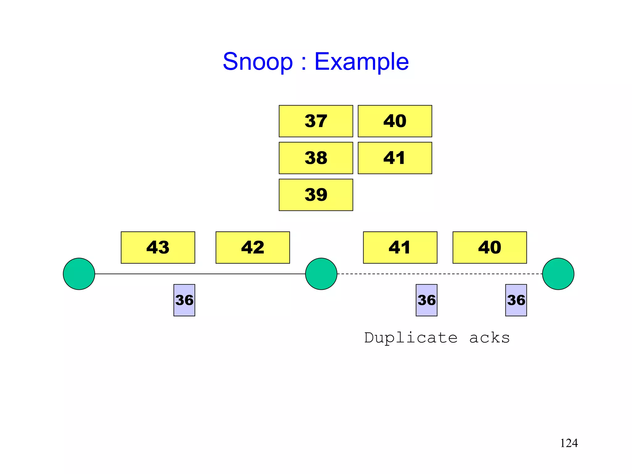
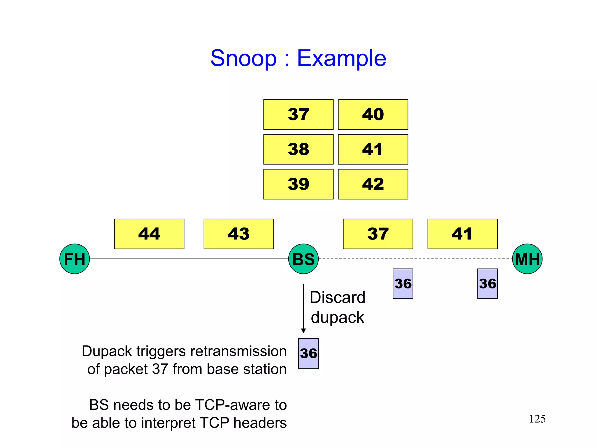
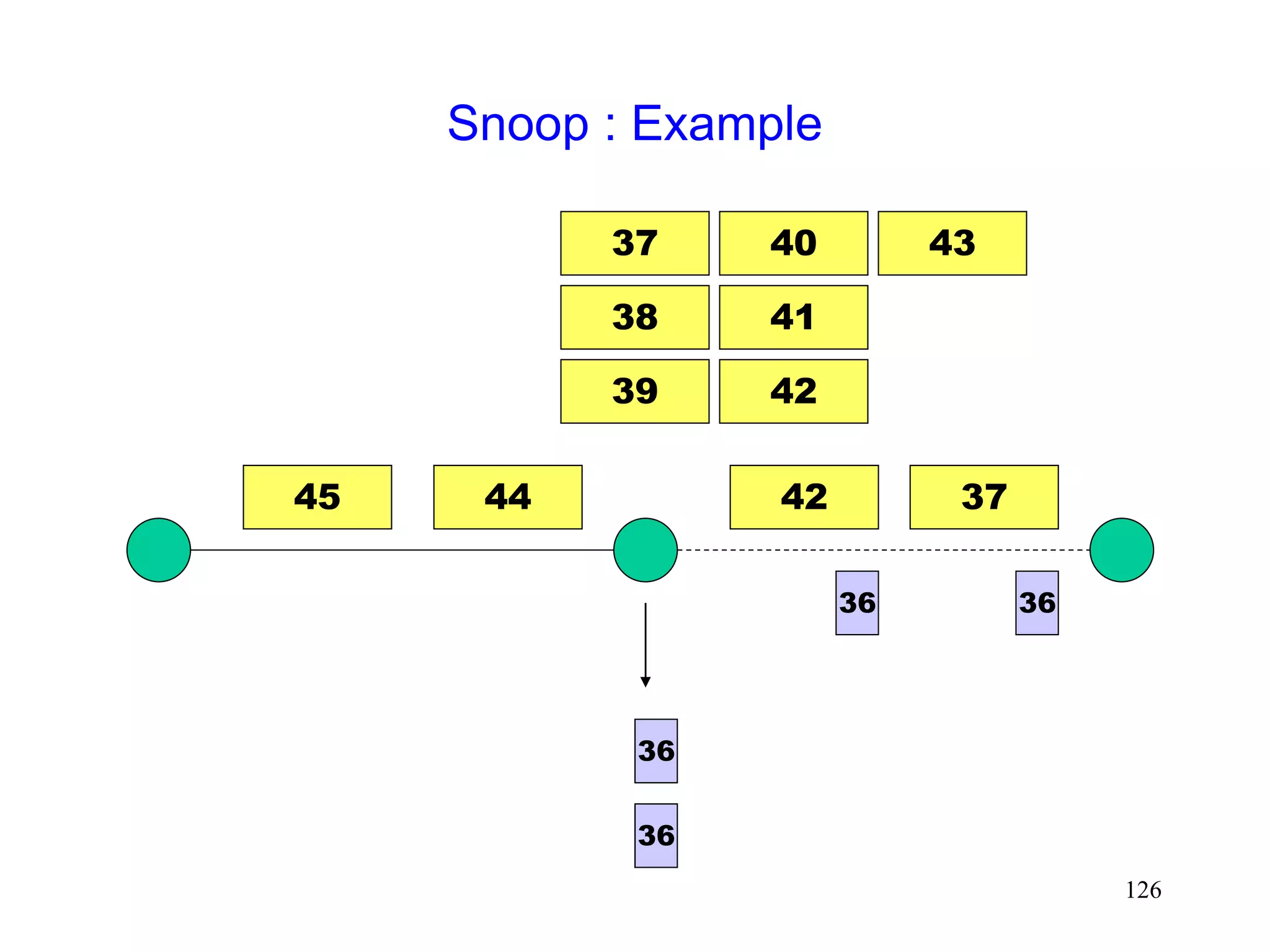
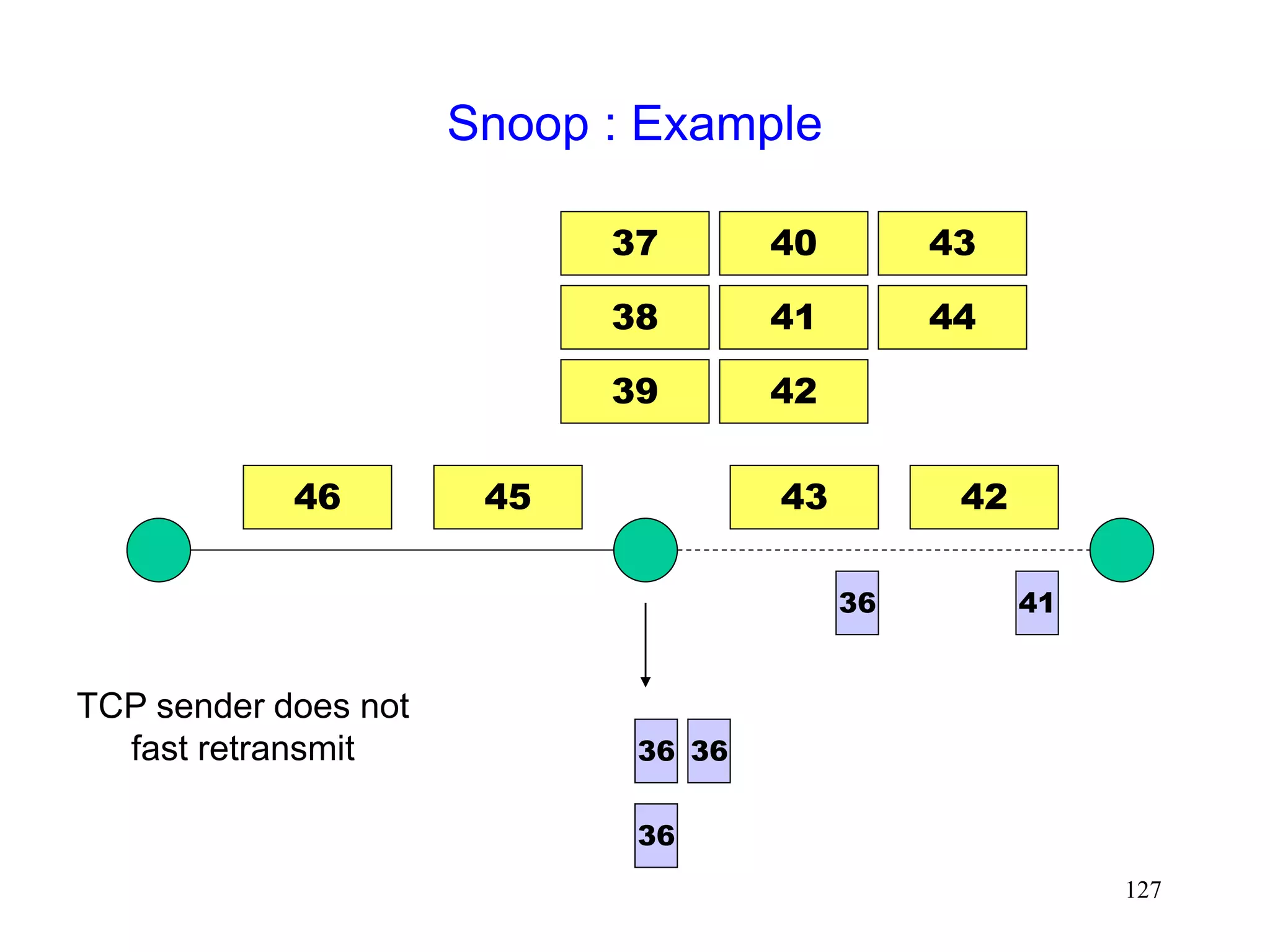
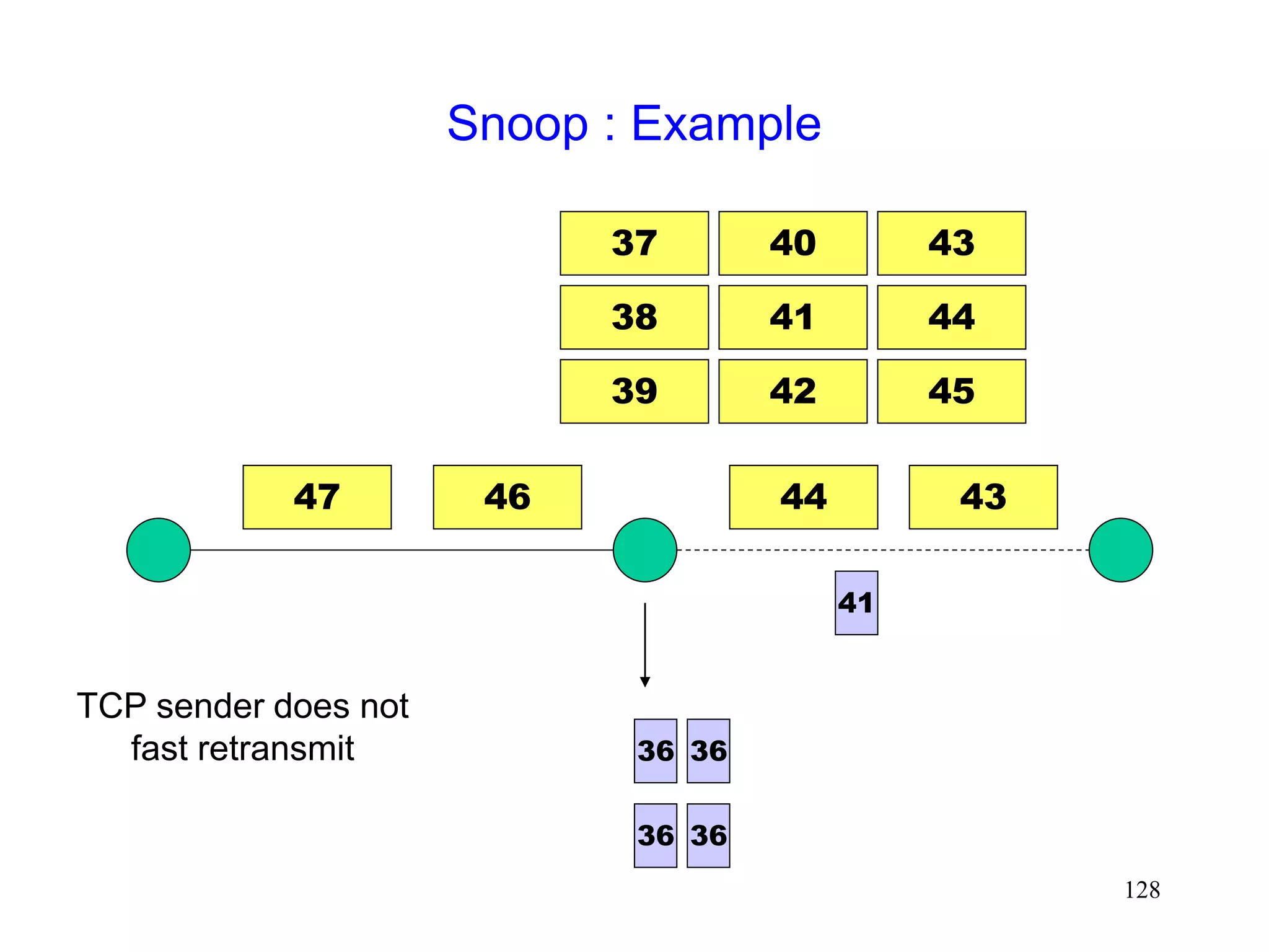
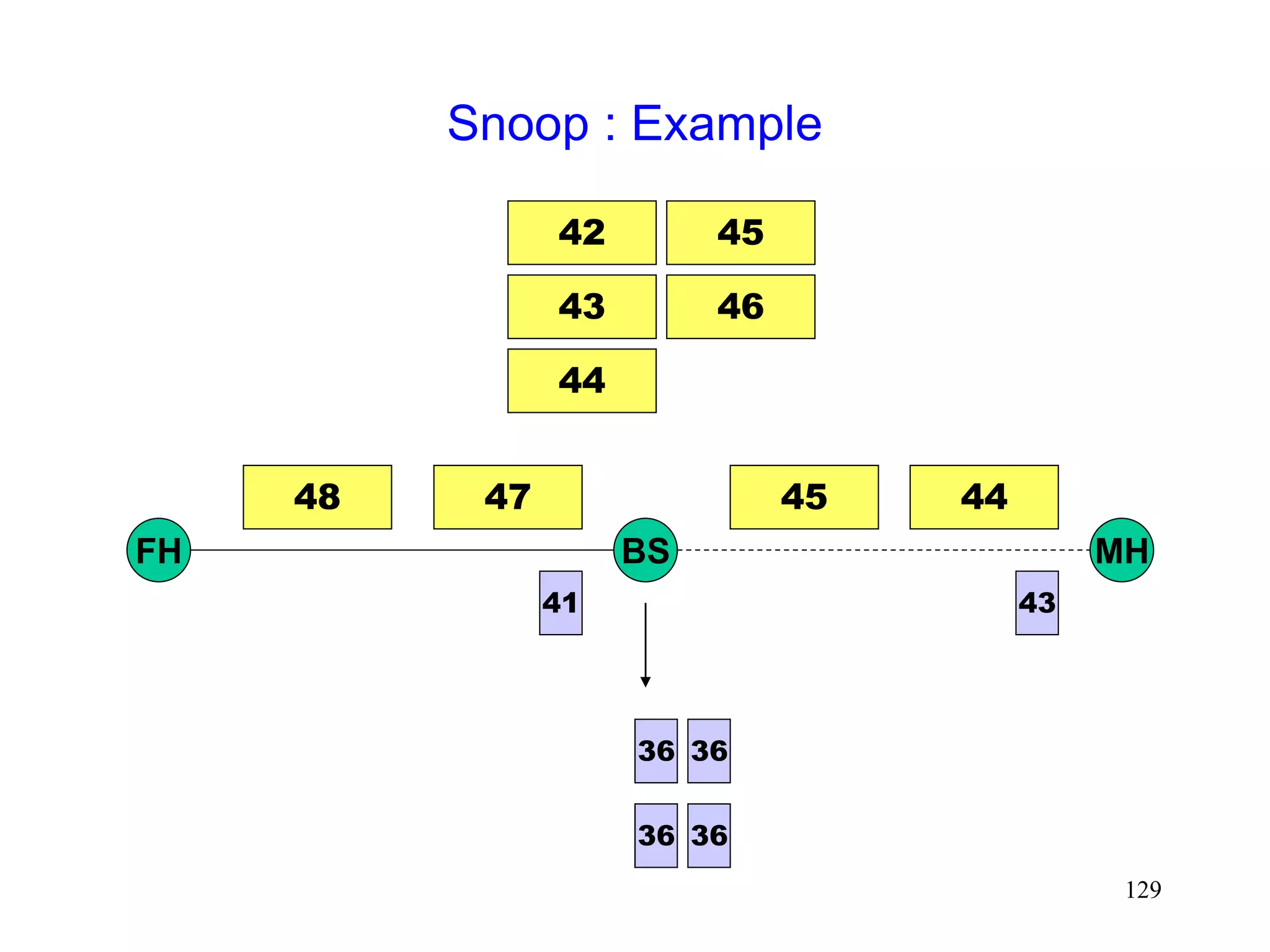
Snoop Protocol [Balakrishnan95acm]
Retains local recovery of Split Connection approach
and link level retransmission schemes
Improves on split connection
end-to-end semantics retained
soft state at base station, instead of hard state](https://image.slidesharecdn.com/tcp-wireless-tutorial-220913150100-d90cc118/85/tcp-wireless-tutorial-ppt-118-320.jpg)


![130
Snoop [Balakrishnan95acm]
0
400000
800000
1200000
1600000
2000000
16K
32K
64K
128K
256K
no
error
1/error rate (in bytes)
bits/sec
base TCP
Snoop
2 Mbps Wireless link](https://image.slidesharecdn.com/tcp-wireless-tutorial-220913150100-d90cc118/85/tcp-wireless-tutorial-ppt-130-320.jpg)


![135
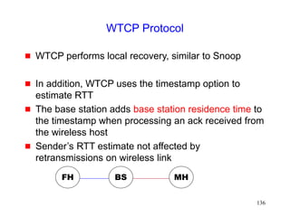
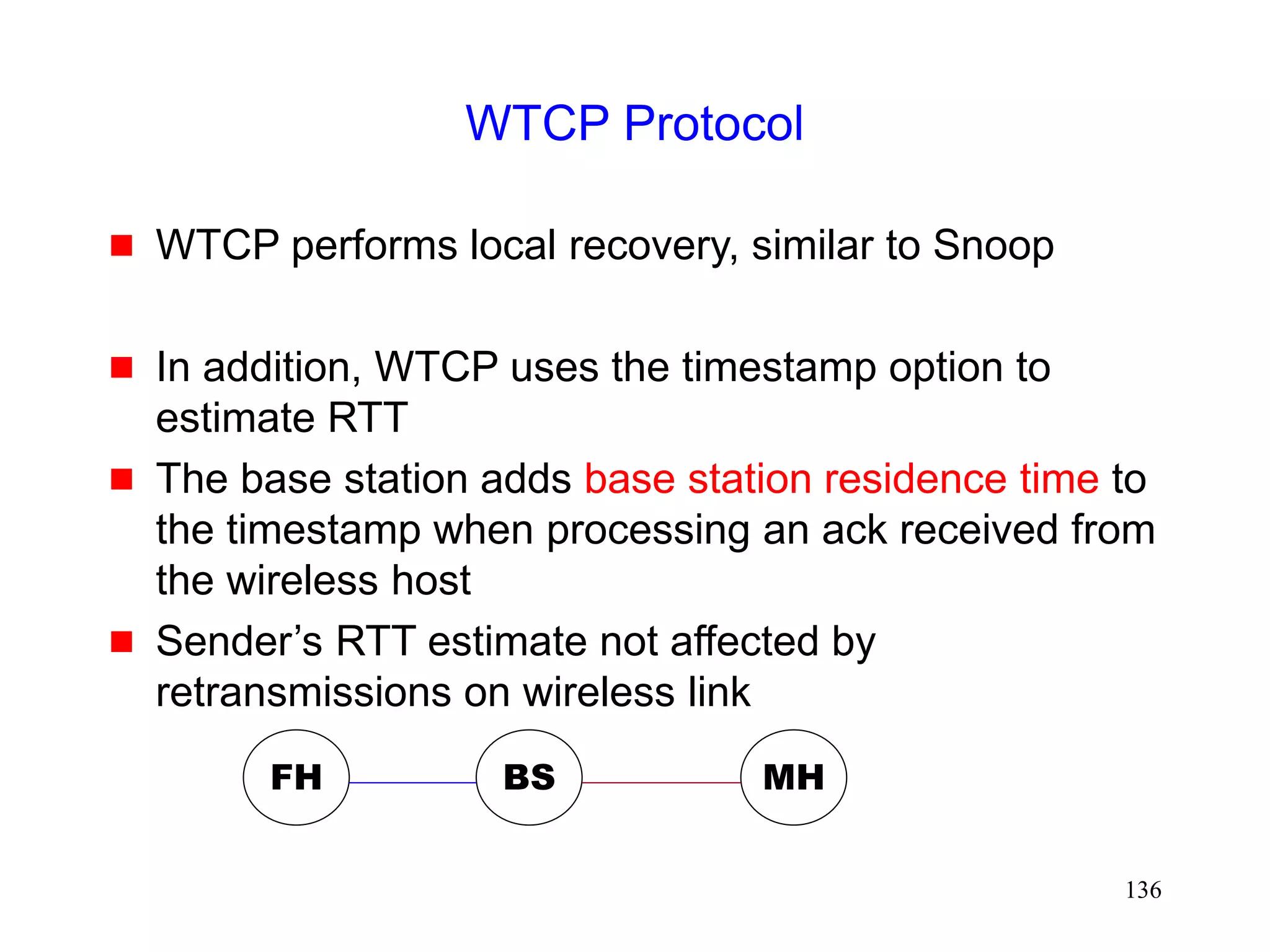
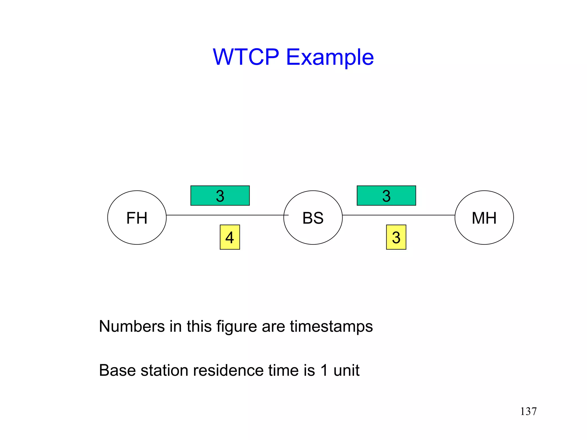
WTCP Protocol [Ratnam98]
Snoop hides wireless losses from the sender
But sender’s RTT estimates may be larger in
presence of errors
Larger RTO results in slower response for congestion
losses
FH MH
BS](https://image.slidesharecdn.com/tcp-wireless-tutorial-220913150100-d90cc118/85/tcp-wireless-tutorial-ppt-135-320.jpg)

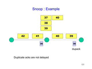
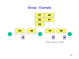
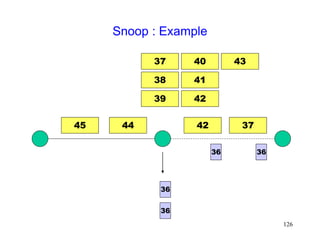
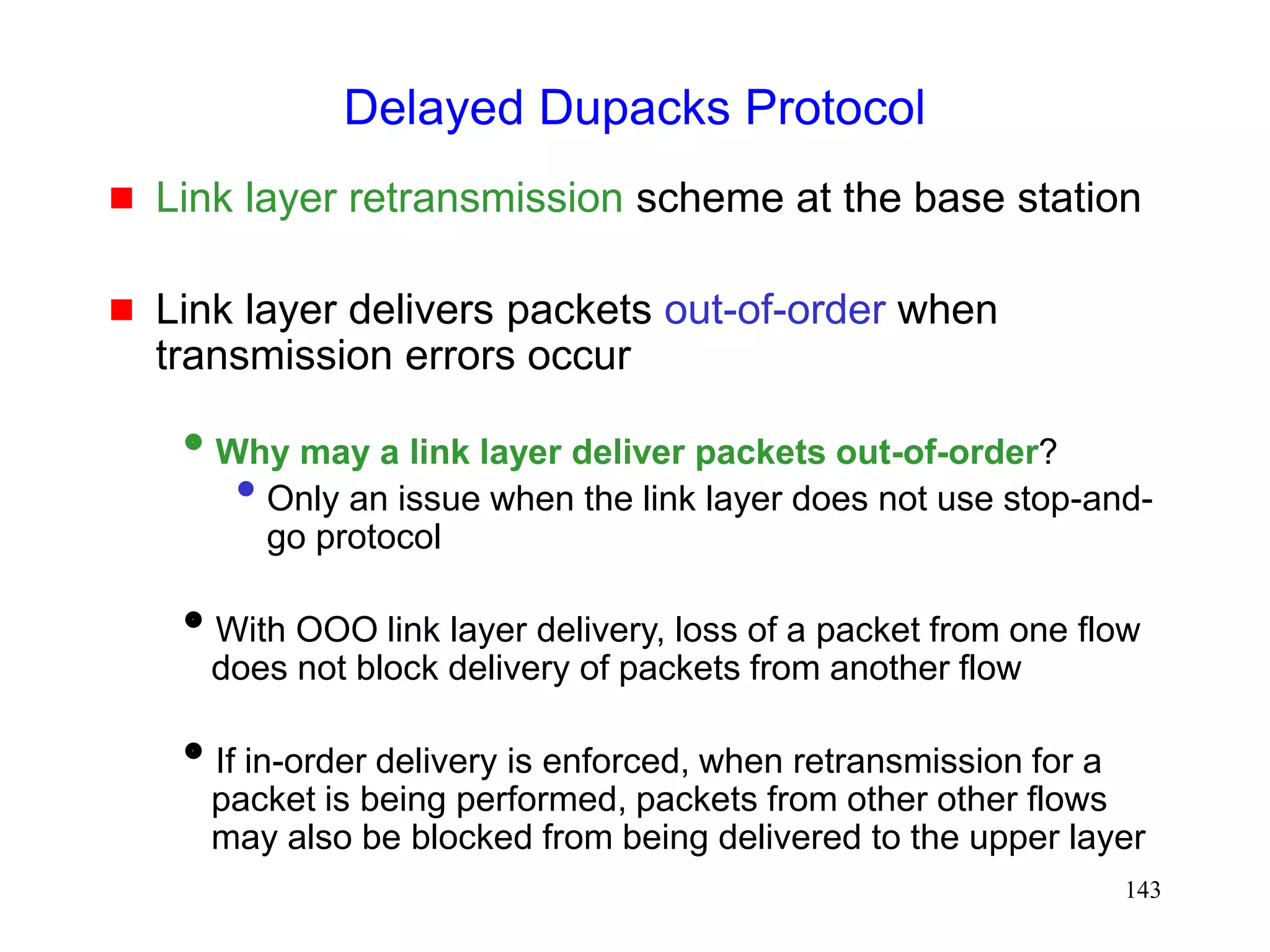
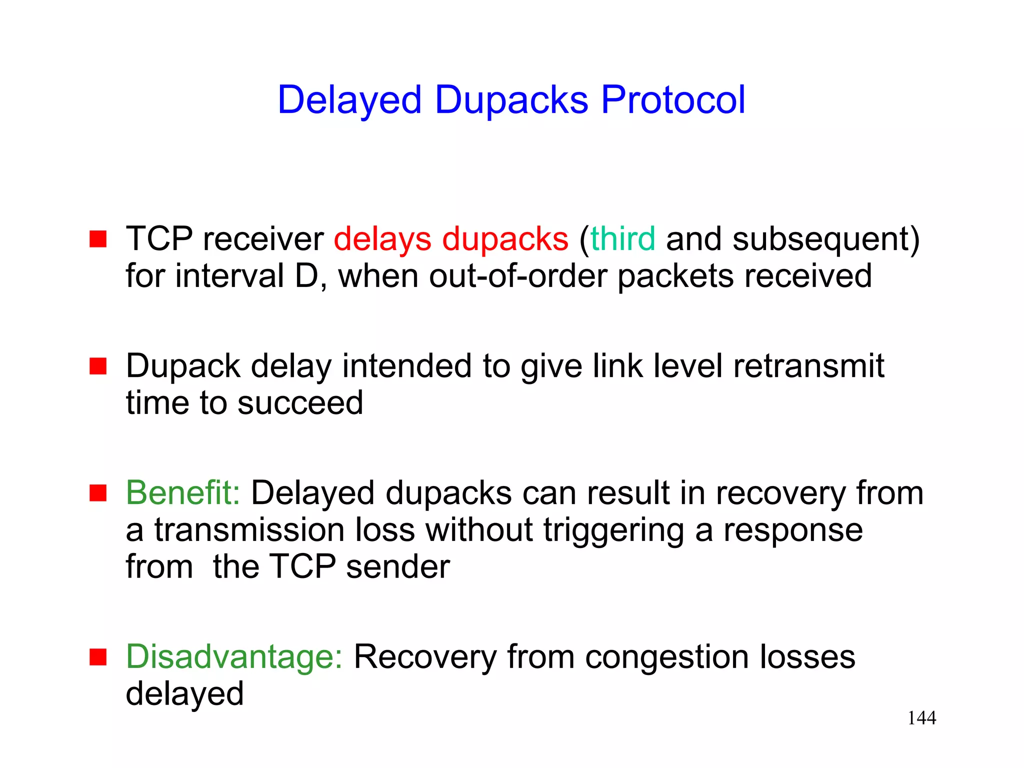
![141
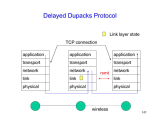
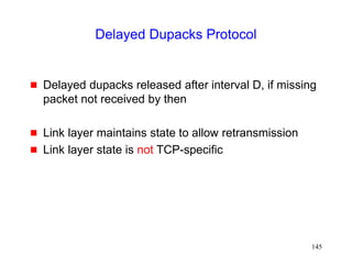
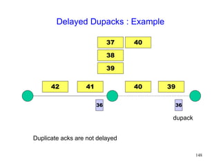
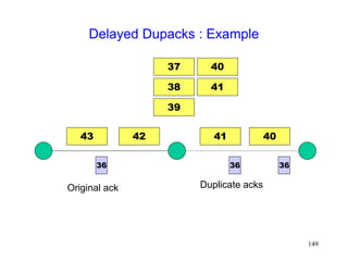
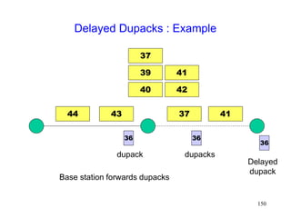
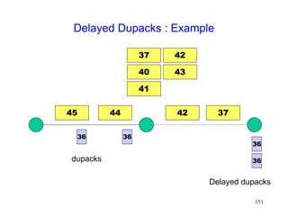
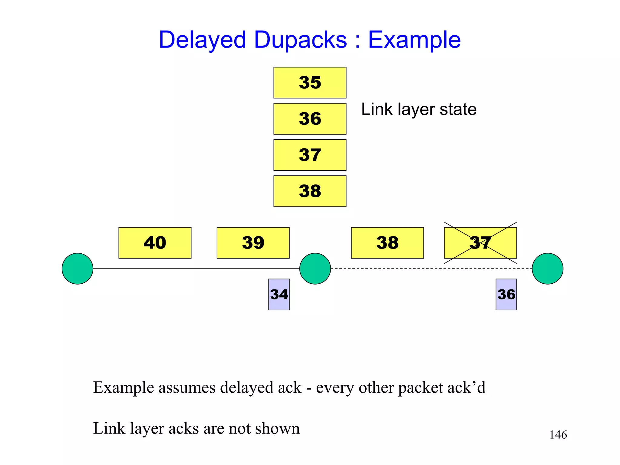
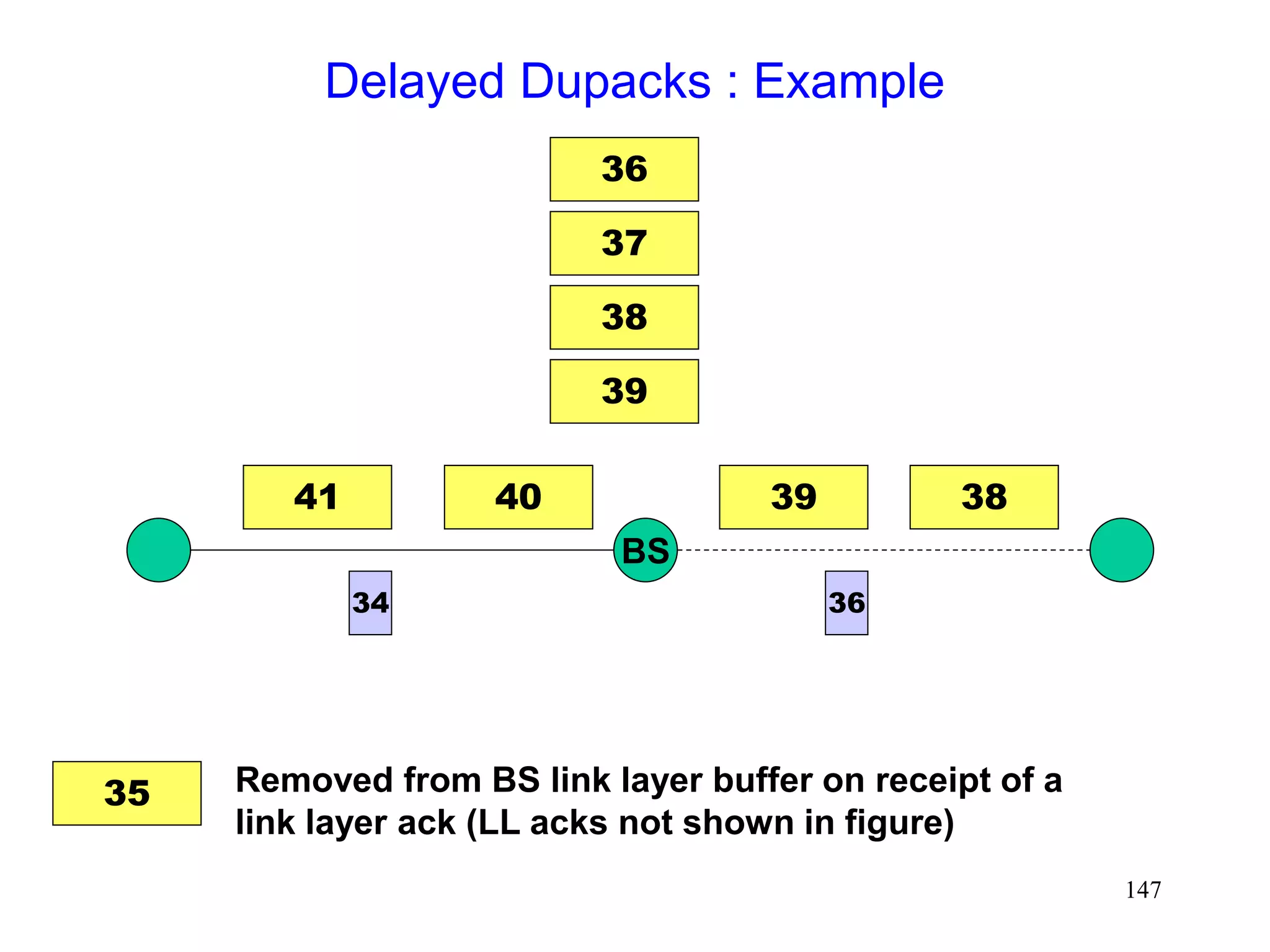
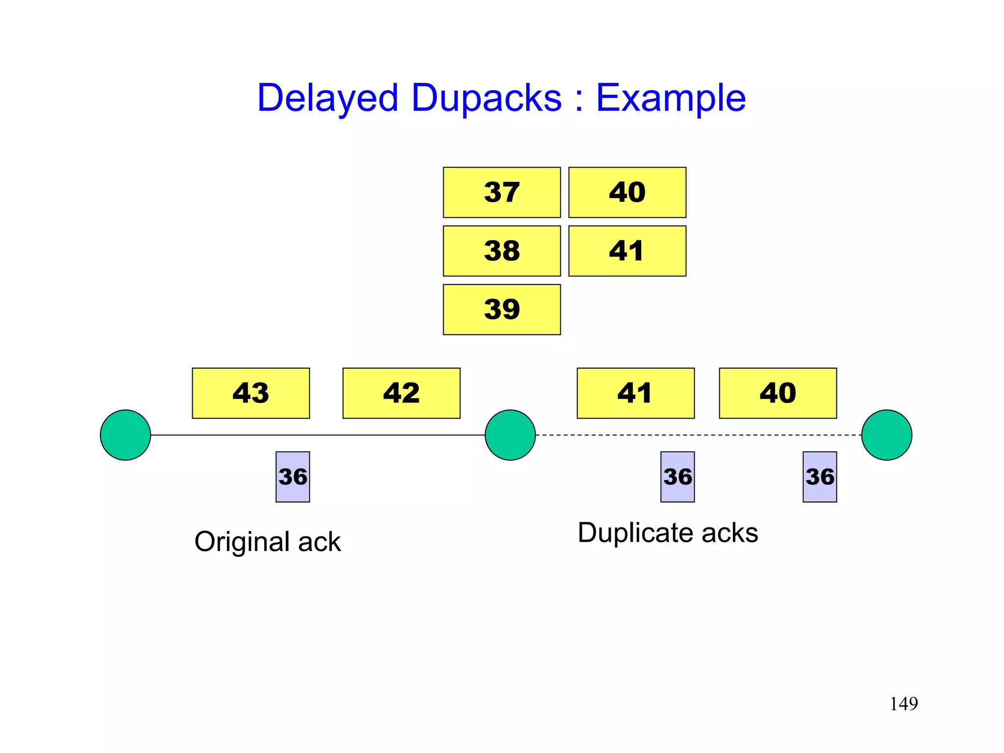
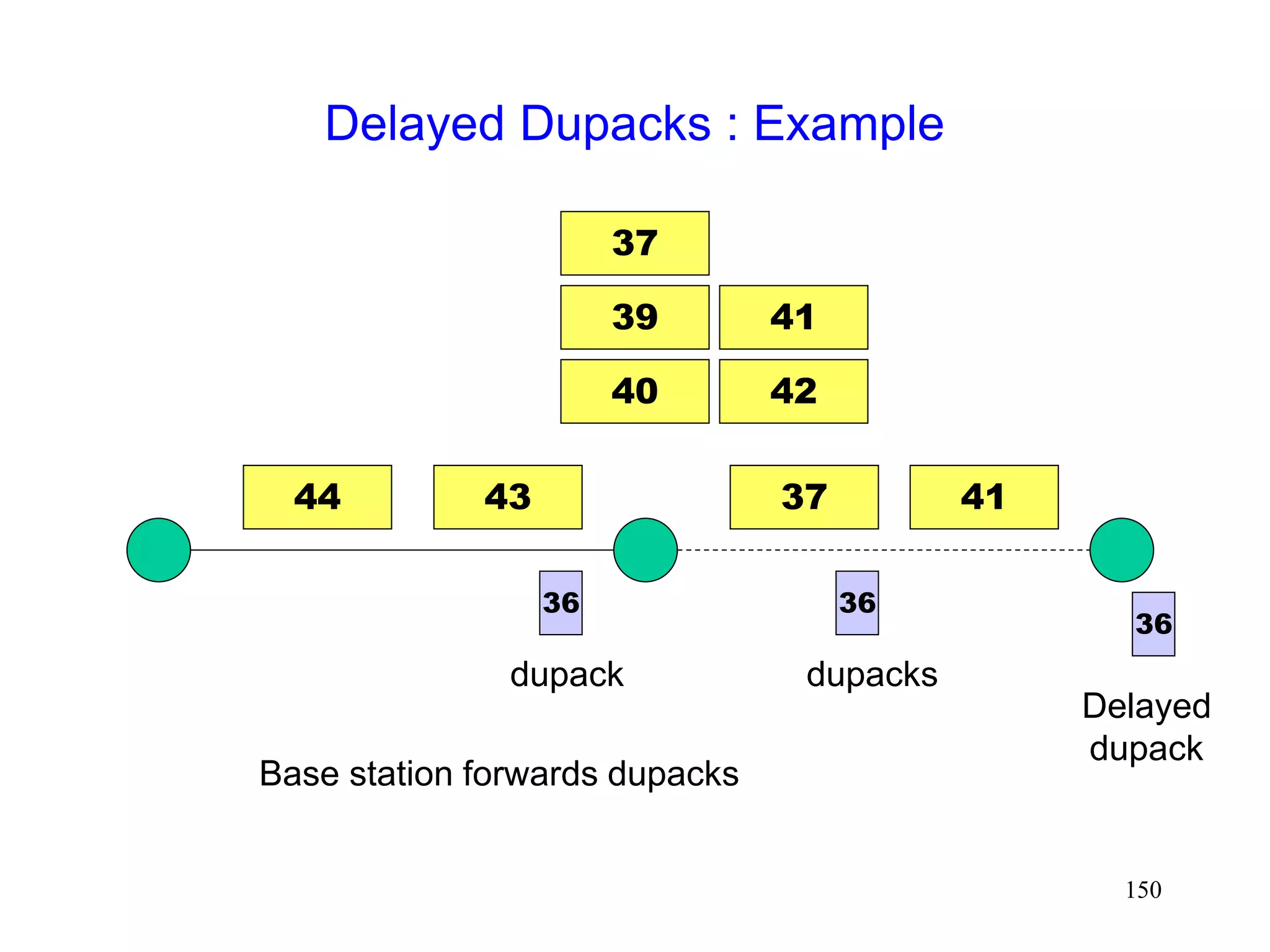
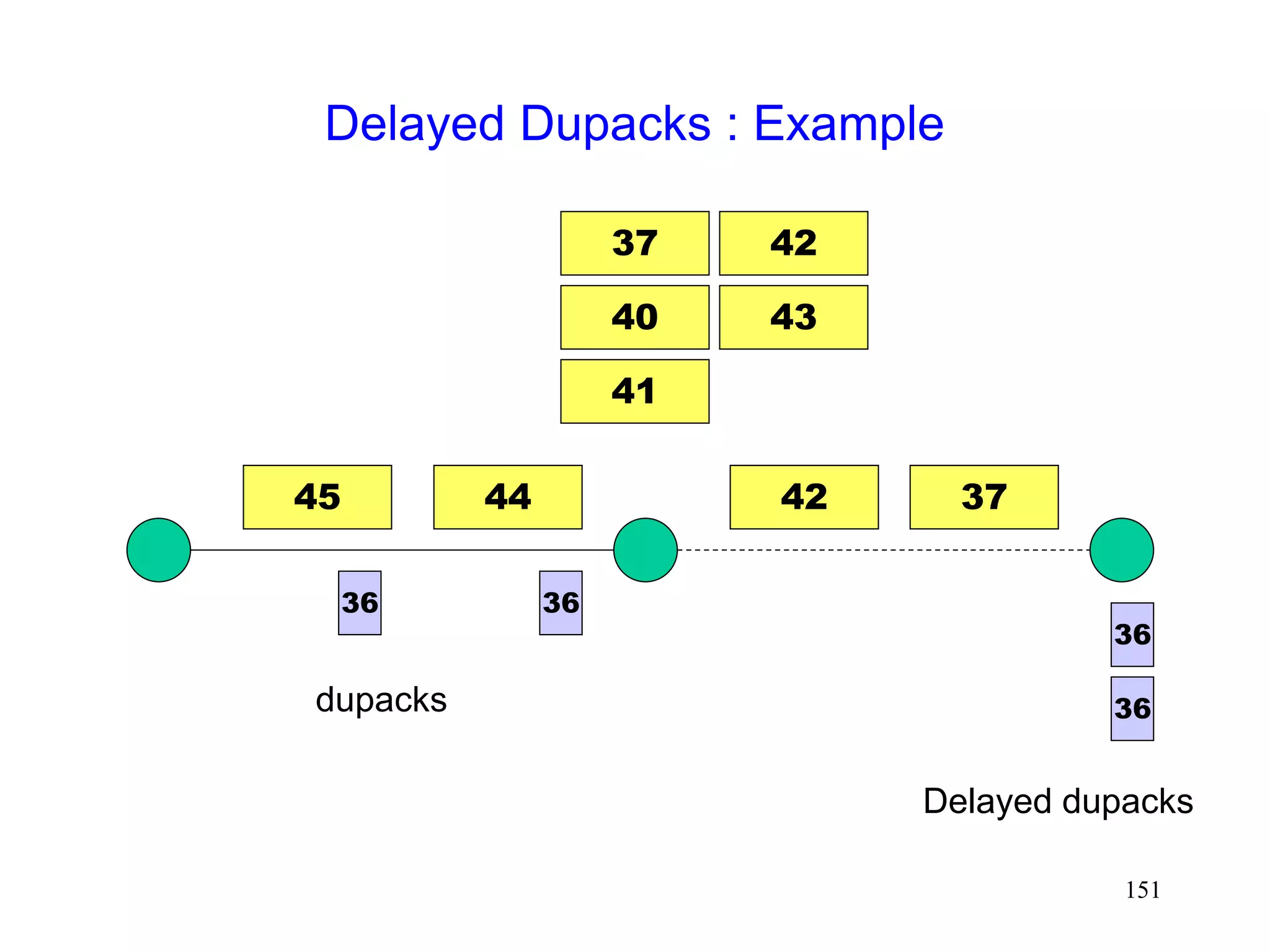
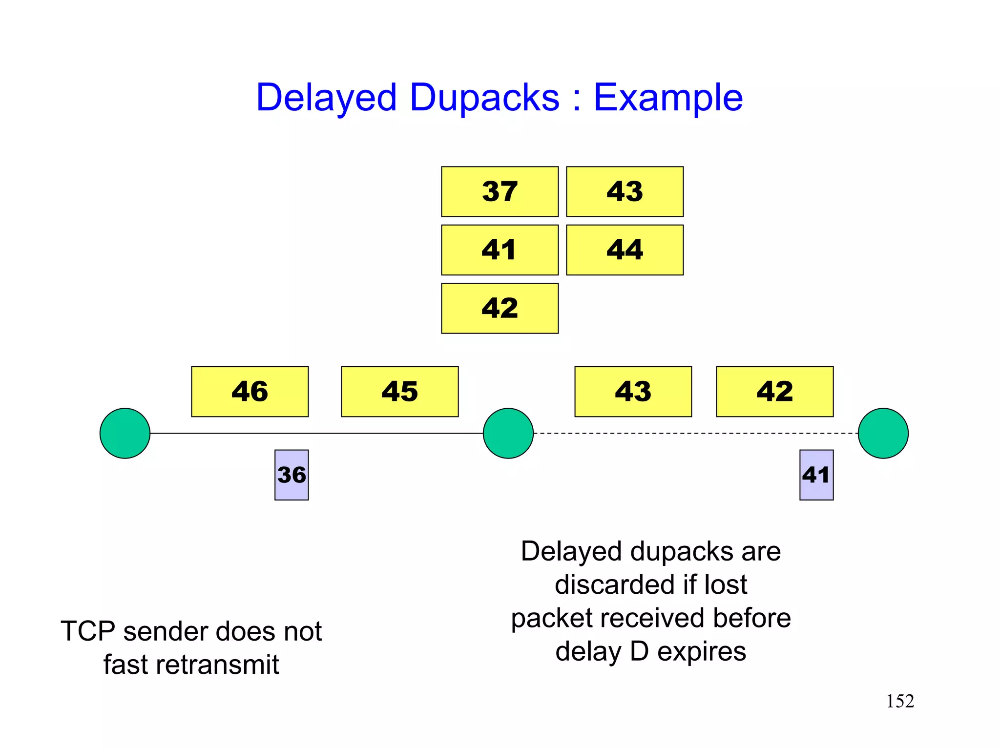
Delayed Dupacks Protocol [Mehta98,Vaidya99]
Attempts to imitate Snoop, without making the base
station TCP-aware
Snoop implements two features at the base station
link layer retransmission
reducing interference between TCP and link layer
retransmissions (by dropping dupacks)
Delayed Dupacks implements the same two features
at BS : link layer retransmission
at MH : reducing interference between TCP and link layer
retransmissions (by delaying dupacks)](https://image.slidesharecdn.com/tcp-wireless-tutorial-220913150100-d90cc118/85/tcp-wireless-tutorial-ppt-141-320.jpg)


![153
Delayed Dupacks [Vaidya99]
0
400000
800000
1200000
1600000
2000000
16384
32768
65536
1E+05
1/error rate (in bytes)
base TCP
dupack delay
80ms + LL
Retransmit
Only LL
retransmit
2 Mbps wireless duplex link with 20 ms delay
No congestion losses
20 ms 20 ms
10 Mbps 2 Mbps](https://image.slidesharecdn.com/tcp-wireless-tutorial-220913150100-d90cc118/85/tcp-wireless-tutorial-ppt-153-320.jpg)
![154
Delayed Dupacks [Vaidya99]
0
20000
40000
60000
80000
100000
120000
140000
160000
16384
32768
65536
1E+05
1/error rate (in bytes)
base TCP
dupack delay
80ms + LL
Retransmit
Only LL
retransmit
5% packet loss due to congestion
20 ms 20 ms
10 Mbps 2 Mbps](https://image.slidesharecdn.com/tcp-wireless-tutorial-220913150100-d90cc118/85/tcp-wireless-tutorial-ppt-154-320.jpg)


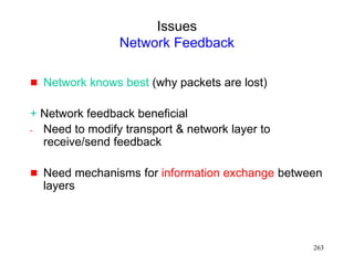
![160
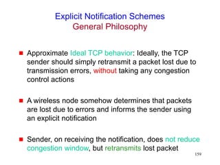
Explicit Notification Schemes
Motivated by the Explicit Congestion Notification
(ECN) proposals [Floyd94]
Variations proposed in literature differ in
who sends explicit notification
how they know to send the explicit notification
what the sender does on receiving the notification](https://image.slidesharecdn.com/tcp-wireless-tutorial-220913150100-d90cc118/85/tcp-wireless-tutorial-ppt-160-320.jpg)
![163
Explicit Loss Notification [Balakrishnan98]
when MH is the TCP sender
Wireless link first on the path from sender to receiver
The base station keeps track of holes in the packet
sequence received from the sender
When a dupack is received from the receiver, the
base station compares the dupack sequence number
with the recorded holes
if there is a match, an ELN bit is set in the dupack
When sender receives dupack with ELN set, it
retransmits packet, but does not reduce congestion
window
MH FH
BS
4 3 2 1 1
3
4
wireless
Record
hole at 2
1
1
1 1
Dupack with ELN set](https://image.slidesharecdn.com/tcp-wireless-tutorial-220913150100-d90cc118/85/tcp-wireless-tutorial-ppt-163-320.jpg)
![164
Explicit Bad State Notification [Bakshi97]
when MH is TCP receiver
Base station attempts to deliver packets to the MH
using a link layer retransmission scheme
If packet cannot be delivered using a small number of
retransmissions, BS sends a Explicit Bad State
Notification (EBSN) message to TCP sender
When TCP sender receives EBSN, it resets its timer
timeout delayed, when wireless channel in bad state](https://image.slidesharecdn.com/tcp-wireless-tutorial-220913150100-d90cc118/85/tcp-wireless-tutorial-ppt-164-320.jpg)
![165
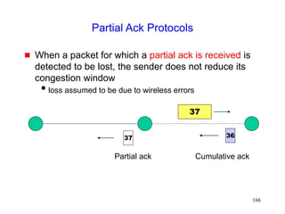
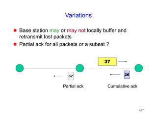
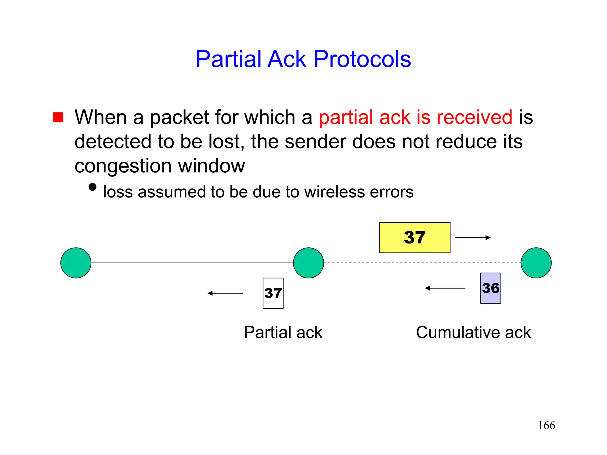
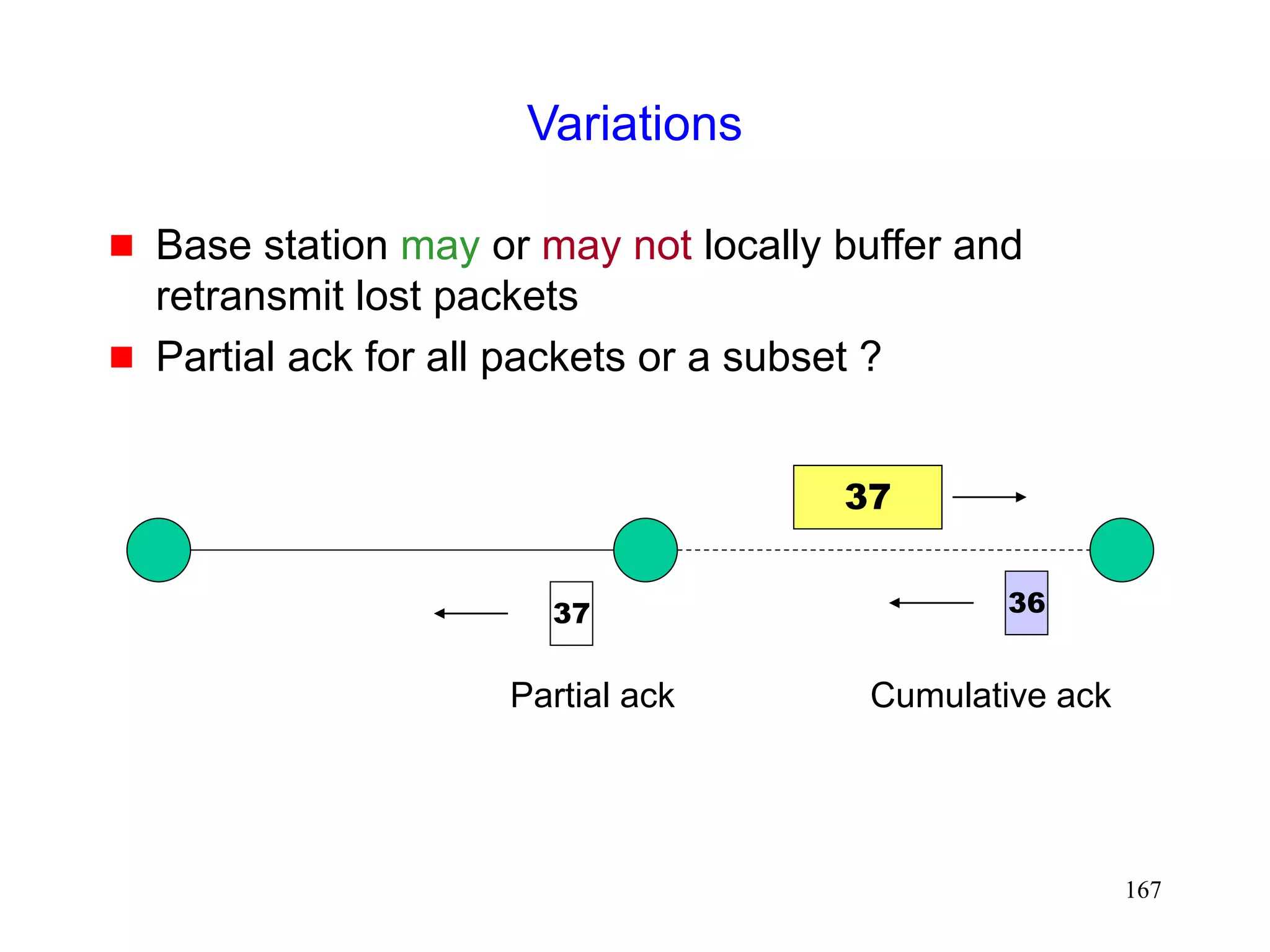
Partial Ack Protocols
[Cobb95][Biaz97]
Send two types of acknowledgements
A partial acknowledgement informs the sender that a
packet was received by an intermediate host
(typically, base station)
Normal TCP cumulative ack needed by the sender for
reliability purposes](https://image.slidesharecdn.com/tcp-wireless-tutorial-220913150100-d90cc118/85/tcp-wireless-tutorial-ppt-165-320.jpg)
![168
Explicit Loss Notification [Biaz99thesis]
when MH is TCP receiver
Attempts to approximate hypothetical ELN proposed
in [Balakrishnan96] for the case when MH is receiver
Caches TCP sequence numbers at base station,
similar to Snoop. But does not cache data packets,
unlike Snoop.
Duplicate acks are tagged with ELN bit before being
forwarded to sender if sequence number for the lost
packet is cached at the base station
Sender takes appropriate action on receiving ELN](https://image.slidesharecdn.com/tcp-wireless-tutorial-220913150100-d90cc118/85/tcp-wireless-tutorial-ppt-168-320.jpg)
![169
Explicit Loss Notification [Biaz99thesis]
when MH is TCP receiver
37
36
37
38
39
39
38
Sequence numbers
cached at base station
37 37
Dupack with ELN](https://image.slidesharecdn.com/tcp-wireless-tutorial-220913150100-d90cc118/85/tcp-wireless-tutorial-ppt-169-320.jpg)
![172
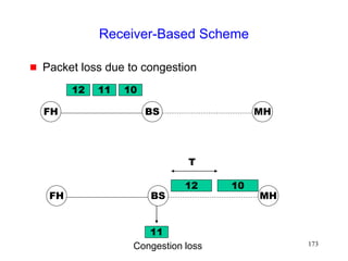
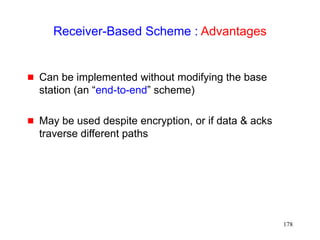
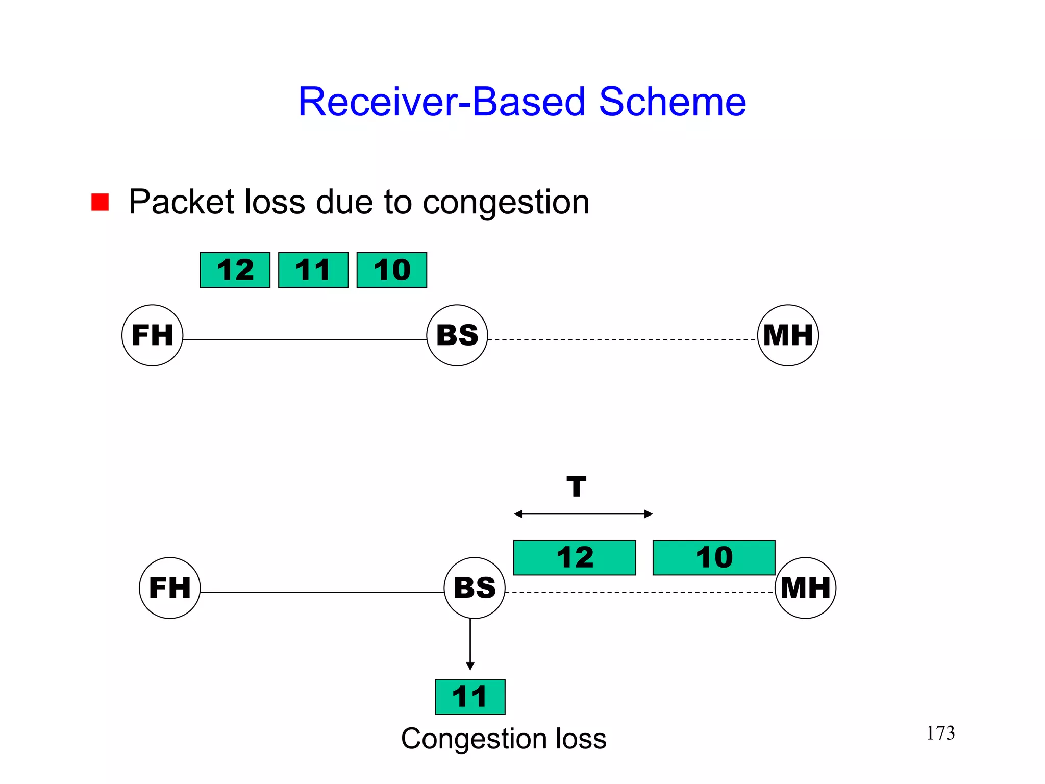
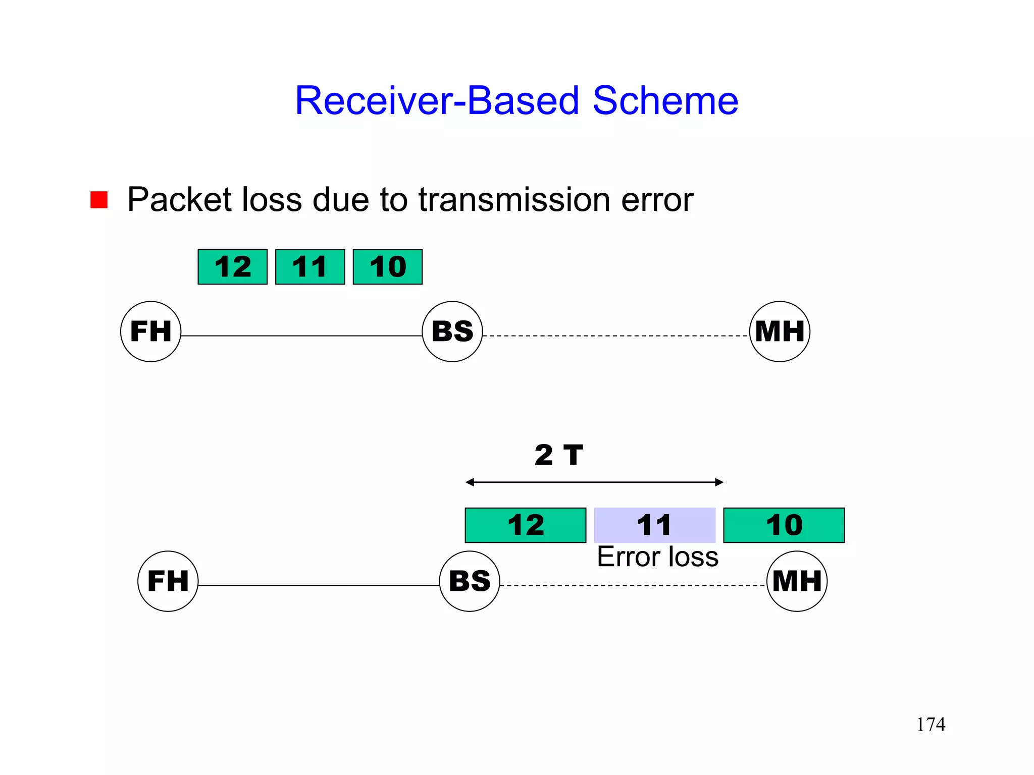
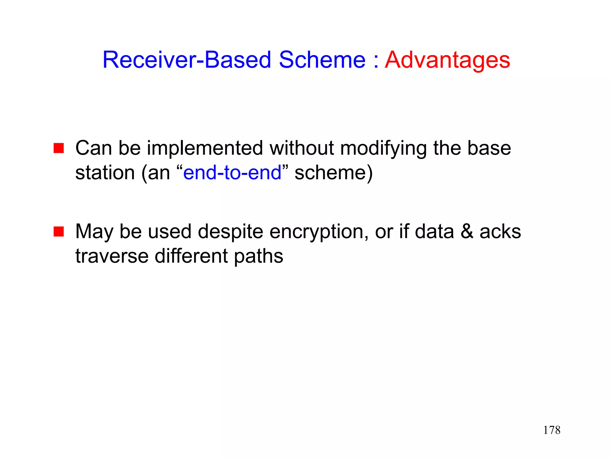
Receiver-Based Scheme [Biaz98Asset]
MH is TCP receiver
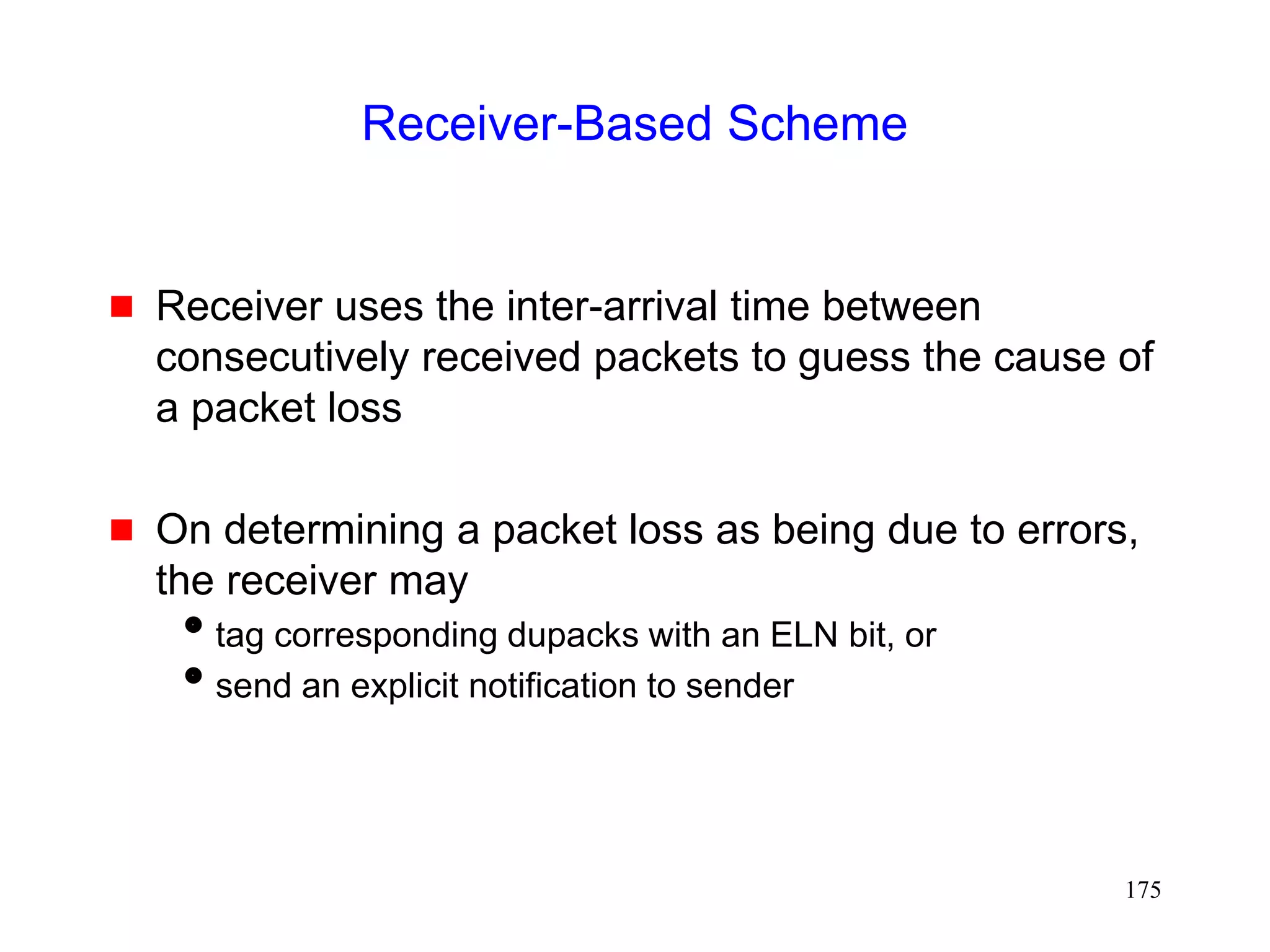
Receiver uses a heuristic to guess cause of packet
loss
When receiver believes that packet loss is due to
errors, it sends a notification to the TCP sender
TCP sender, on receiving the notification, retransmits
the lost packet, but does not reduce congestion
window](https://image.slidesharecdn.com/tcp-wireless-tutorial-220913150100-d90cc118/85/tcp-wireless-tutorial-ppt-172-320.jpg)

![176
Receiver-Based Scheme
Diagnostic Accuracy [Biaz99Asset]
Congestion losses Error losses](https://image.slidesharecdn.com/tcp-wireless-tutorial-220913150100-d90cc118/85/tcp-wireless-tutorial-ppt-176-320.jpg)
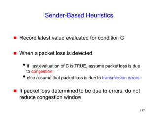
![181
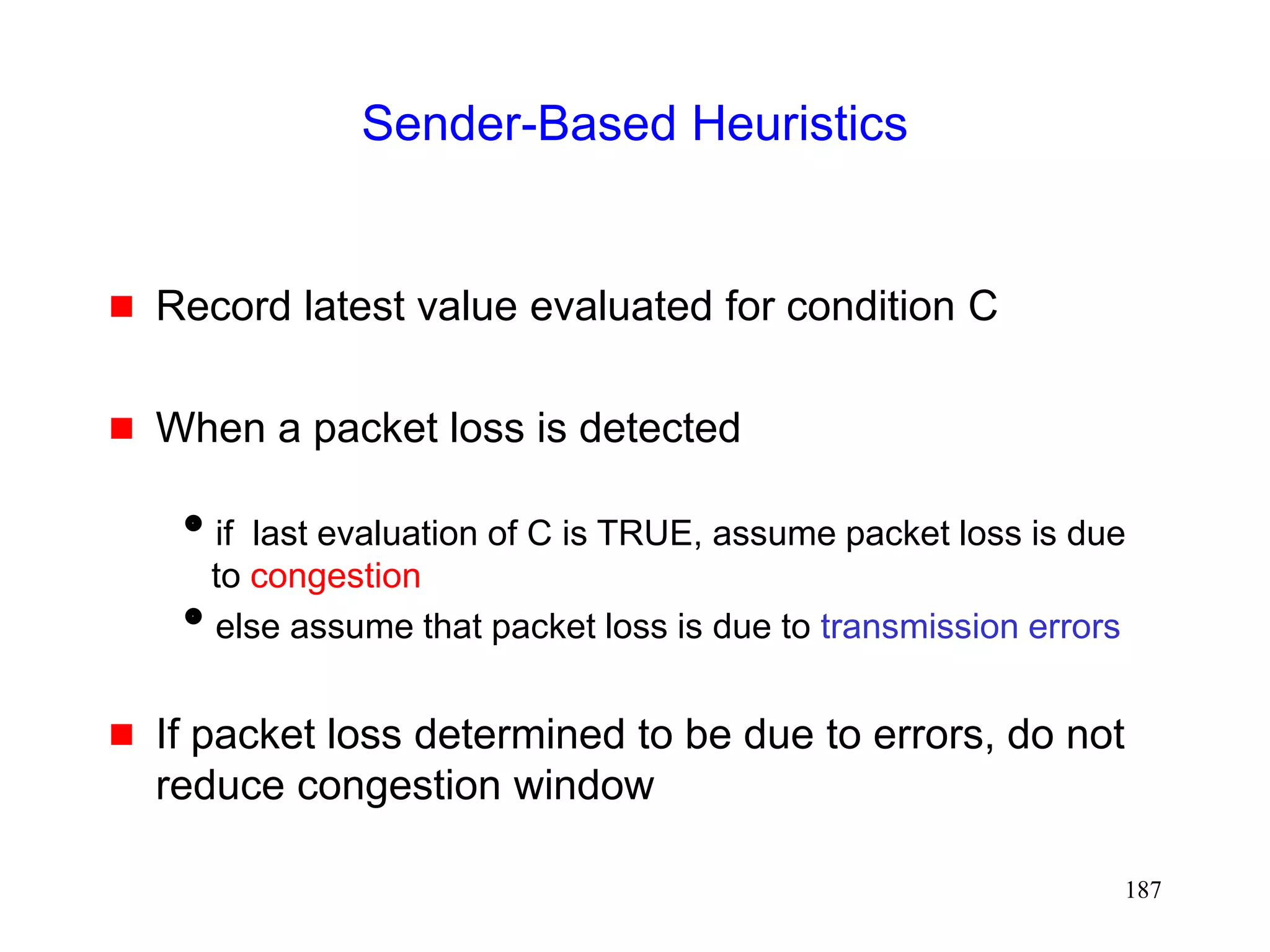
Sender-Based Discrimination Scheme
[Biaz98ic3n,Biaz99techrep]
Sender can attempt to determine cause of a packet
loss
If packet loss determined to be due to errors, do not
reduce congestion window
Sender can only use statistics based on round-trip
times, window sizes, and loss pattern
unless network provides more information (example: explicit
loss notification)](https://image.slidesharecdn.com/tcp-wireless-tutorial-220913150100-d90cc118/85/tcp-wireless-tutorial-ppt-181-320.jpg)
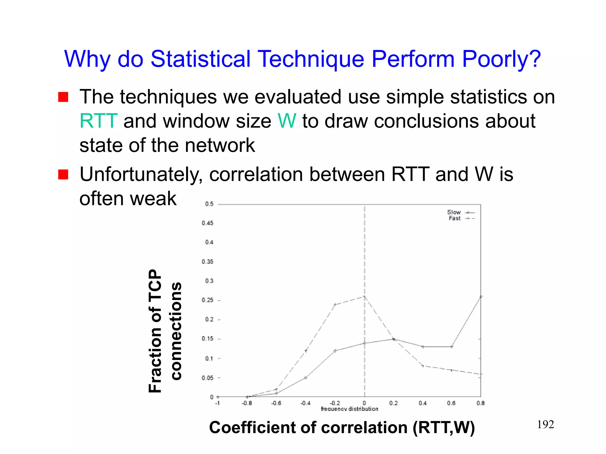
![184
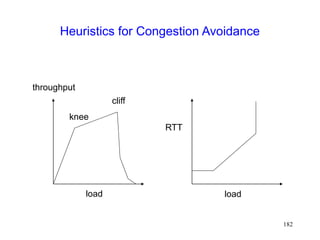
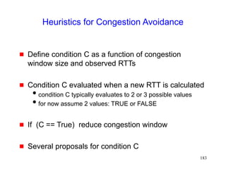
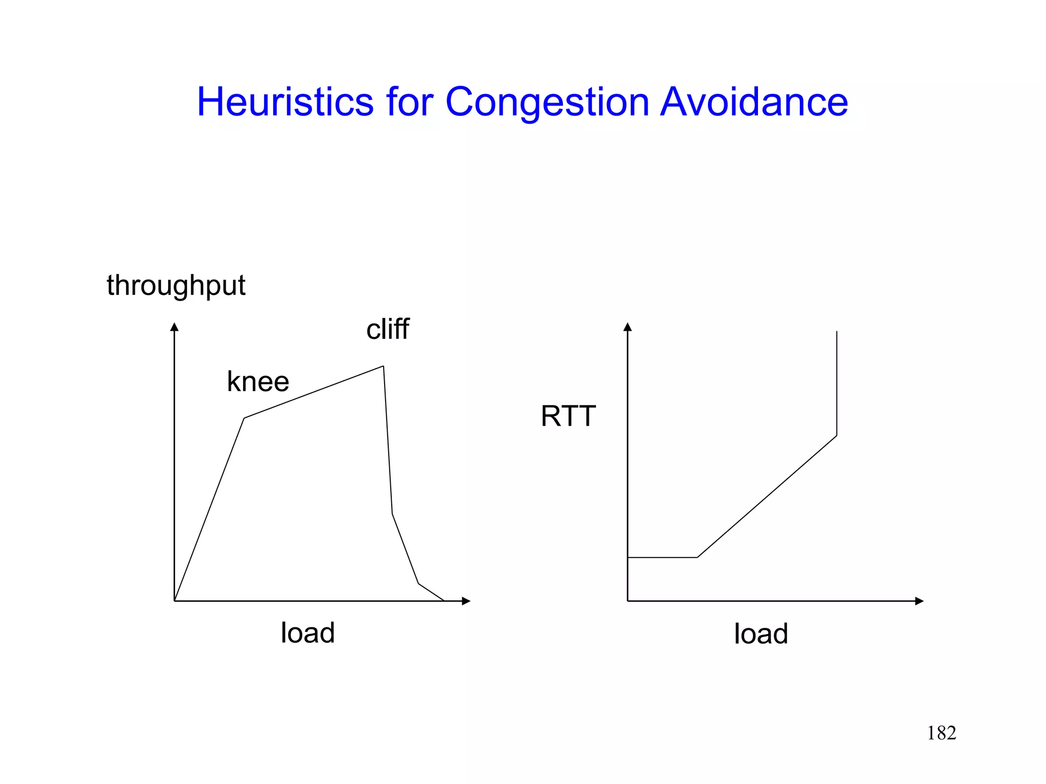
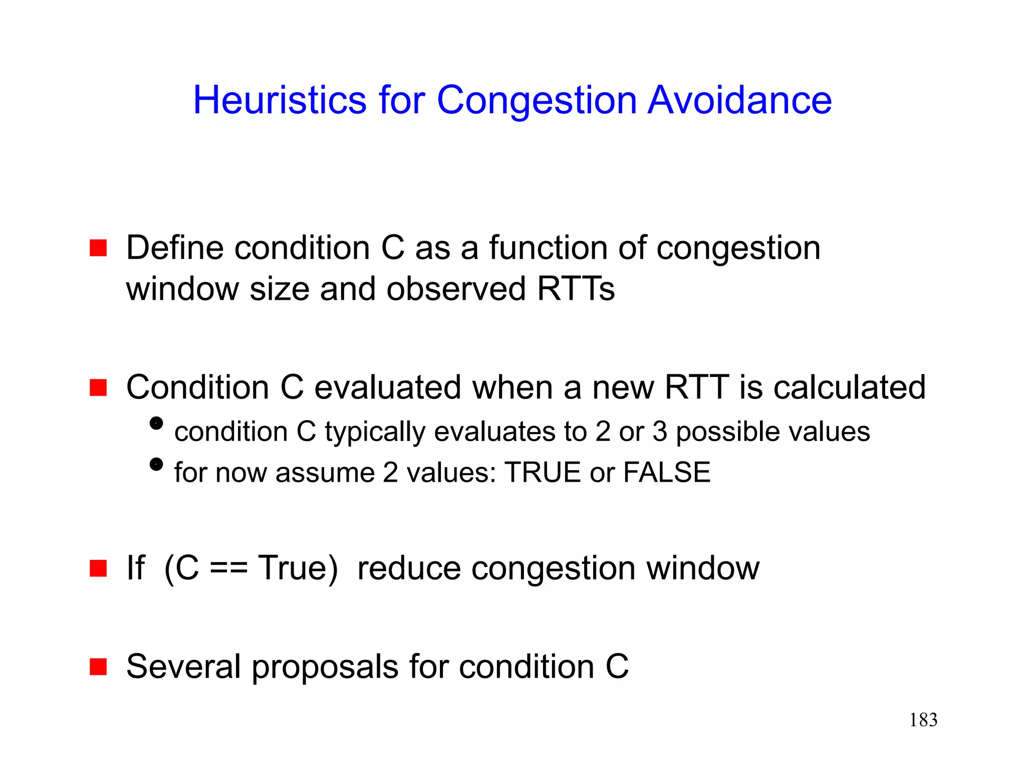
Heuristics for Congestion Avoidance
Some proposals
Normalized Delay Gradient [jain89]
r = [RTT(i)-RTT(i-1)] / [RTT(i)+RTT(i-1)]
w = [W(i)-W(i-1)] / [W(i)+W(i-1)]
Condition C = (r/w > 0)](https://image.slidesharecdn.com/tcp-wireless-tutorial-220913150100-d90cc118/85/tcp-wireless-tutorial-ppt-184-320.jpg)
![185
Heuristics for Congestion Avoidance
Some proposals
Normalized Throughput Gradient [Wang91]
Throughput gradient
TG(i) = [T(i) - T(i-1) ] / [ W(i)-W(i-1)]
Normalized Throughout Gradient
NTG = TG(i) / TG(1)
Condition C = (NTG < 0.5)](https://image.slidesharecdn.com/tcp-wireless-tutorial-220913150100-d90cc118/85/tcp-wireless-tutorial-ppt-185-320.jpg)
![186
Heuristics for Congestion Avoidance
Some proposals
TCP Vegas [Brakmo94]
expected throughput ET = W(i) / RTTmin
actual throughput AT = W(i) / RTT(i)
Condition C = ( ET-AT > beta)](https://image.slidesharecdn.com/tcp-wireless-tutorial-220913150100-d90cc118/85/tcp-wireless-tutorial-ppt-186-320.jpg)
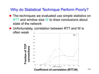
![188
Sender-Based Schemes
Diagnostic Accuracy [Biaz99ic3n]](https://image.slidesharecdn.com/tcp-wireless-tutorial-220913150100-d90cc118/85/tcp-wireless-tutorial-ppt-188-320.jpg)
![189
Sender-Based Schemes
Diagnostic Accuracy [Biaz99ic3n]](https://image.slidesharecdn.com/tcp-wireless-tutorial-220913150100-d90cc118/85/tcp-wireless-tutorial-ppt-189-320.jpg)


![199
Improving TCP-over-Satellite
[Allman98sept][IETF-TCPSAT]
Larger congestion window (window scale option)
maximum window size up to 2^30
Acknowledge every packet (do not delay acks)
Selective acks
fast recovery can only recover one packet loss per RTT
SACKS allow multiple packet recovery per RTT](https://image.slidesharecdn.com/tcp-wireless-tutorial-220913150100-d90cc118/85/tcp-wireless-tutorial-ppt-199-320.jpg)
![200
Larger Initial Window
[Allman98september] [Allman98august]
Allows initial window size of cwnd to be up to
approximately 4 Kbyte
Larger initial window results in faster window growth
during slow start
avoids wait for delayed ack timers (which will occur with
cwnd = 1 MSS)
larger initial window requires fewer RTTs to reach ssthresh](https://image.slidesharecdn.com/tcp-wireless-tutorial-220913150100-d90cc118/85/tcp-wireless-tutorial-ppt-200-320.jpg)
![201
Byte Counting [Allman98august]
Increase window by number of new bytes ack’d in an
acknowledgement, instead of 1 MSS per ack
Speeds up window growth despite delayed or lost
acks
Need to reduce bursts from sender
limiting size of window growth per ack
rate control](https://image.slidesharecdn.com/tcp-wireless-tutorial-220913150100-d90cc118/85/tcp-wireless-tutorial-ppt-201-320.jpg)
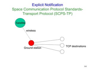
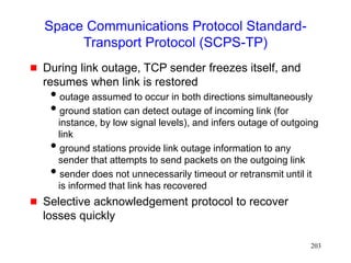
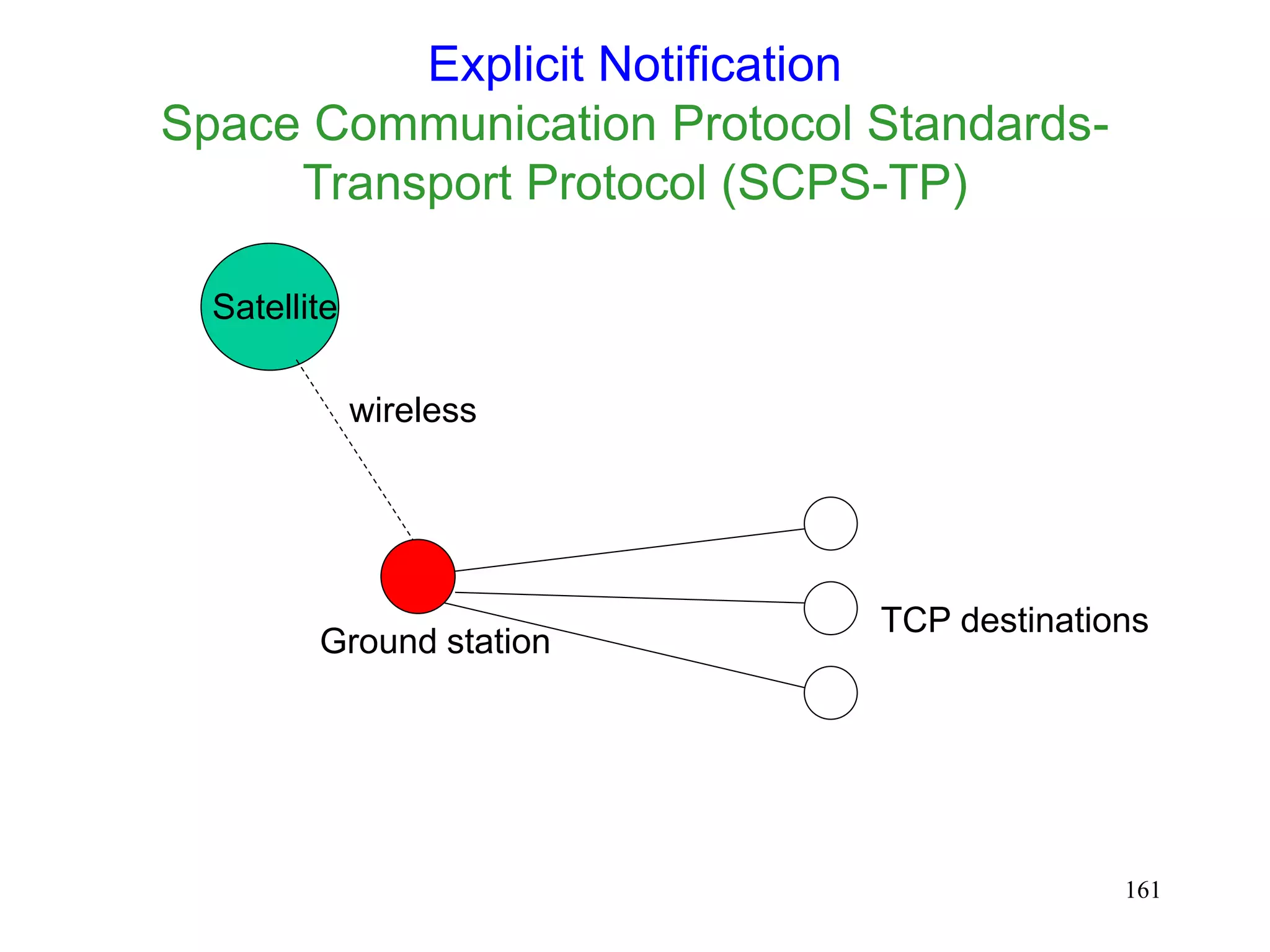
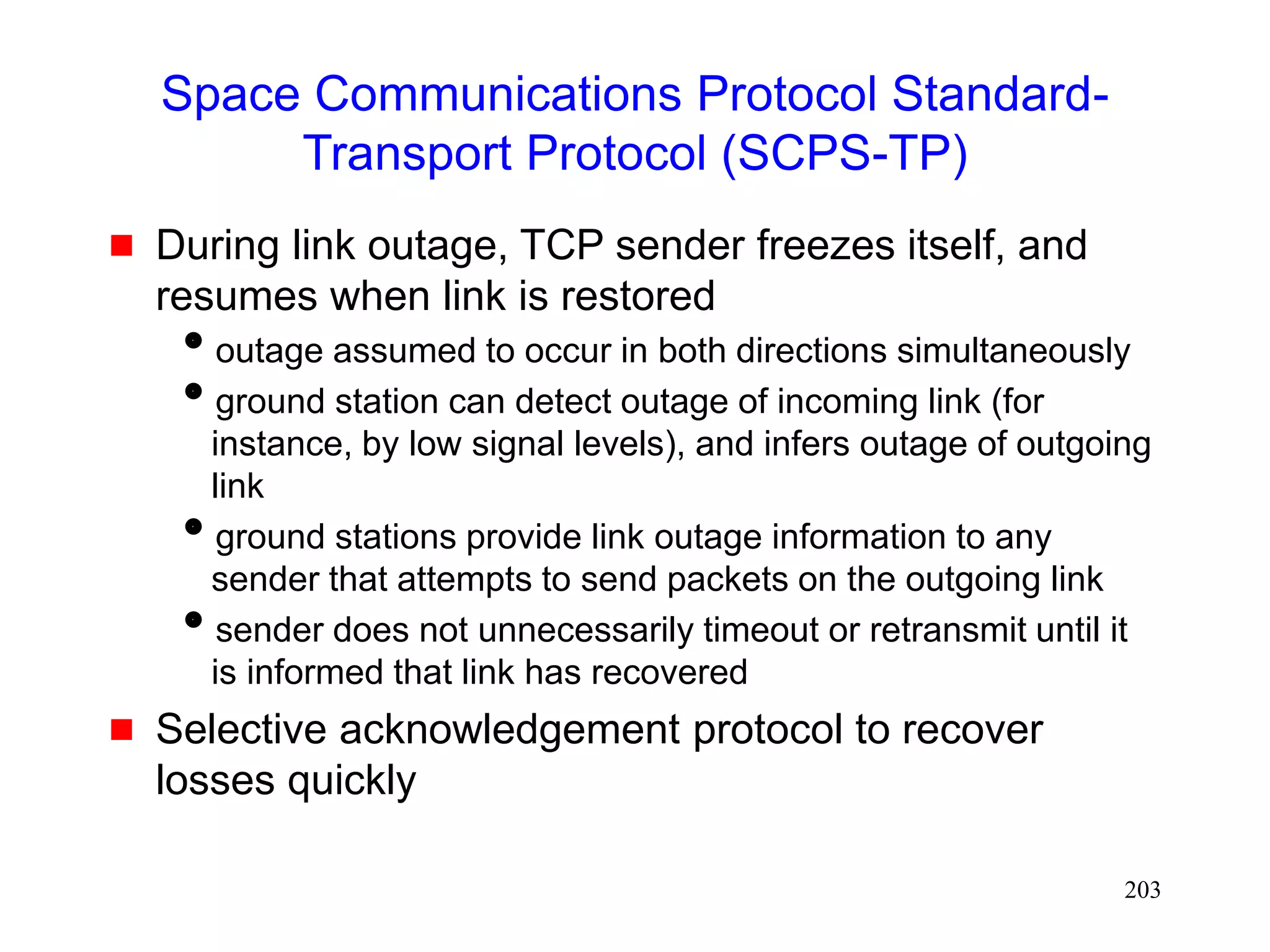
![202
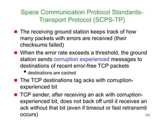
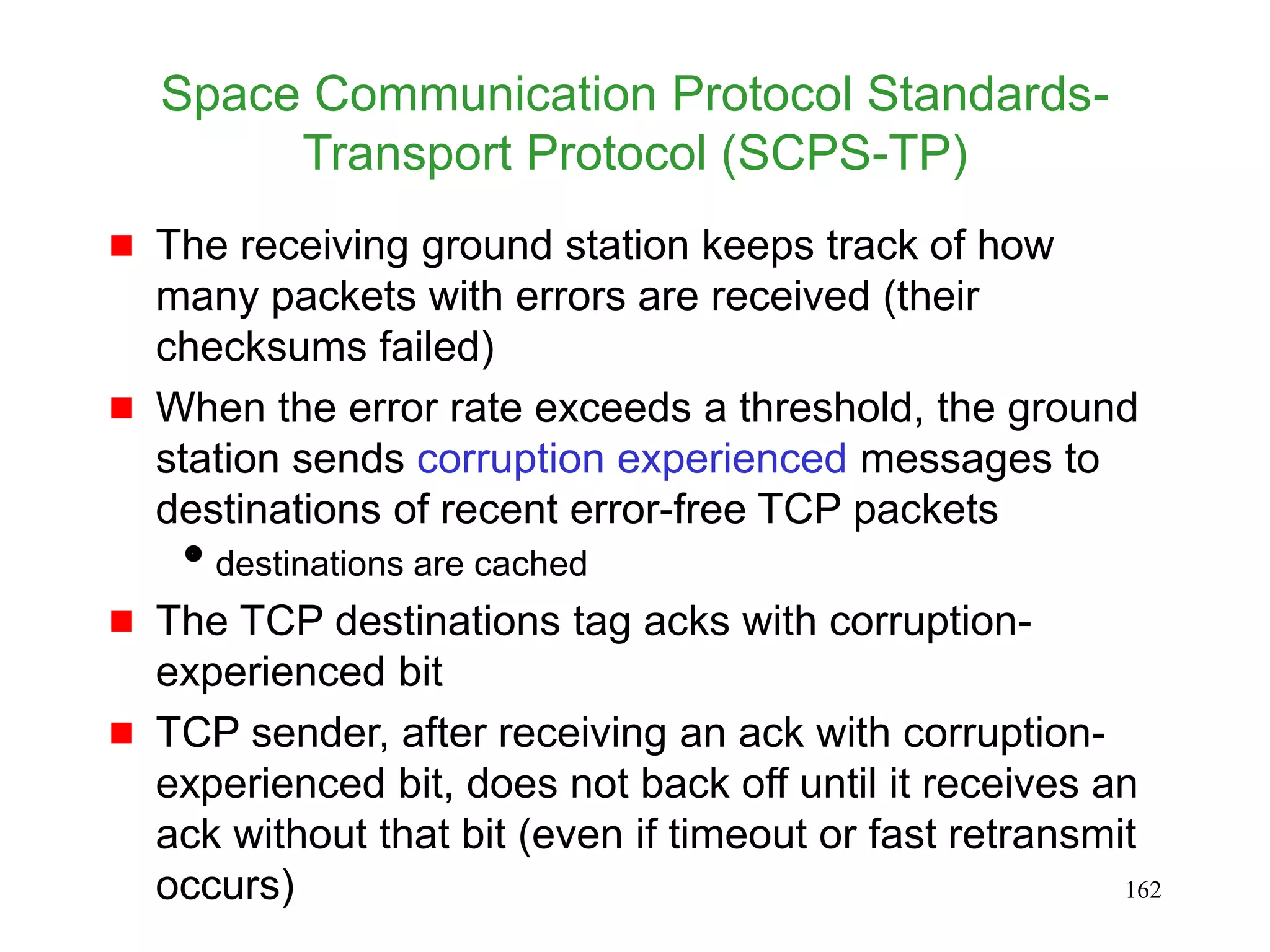
Space Communications Protocol Standard-
Transport Protocol (SCPS-TP) [Durst96]
Sender makes default assumption about source of
packet loss
default assumption can be set by network manager on a
per-route basis
default assumption can be changed due to explicit feedback
from the network
Congestion control algorithm derived from TCP-
Vegas, to bound window growth, to reduce
congestion-induced losses](https://image.slidesharecdn.com/tcp-wireless-tutorial-220913150100-d90cc118/85/tcp-wireless-tutorial-ppt-202-320.jpg)
![204
Satellite Transport Protocol (STP)
[Henderson98]
Uses split connection approach
Protocol on satellite channel different from TCP
selective negative acks when receiver detects losses
no retransmission timer
transmitter periodically requests receiver to ack received
data
reduces reverse channel bandwidth usage when losses are
rare](https://image.slidesharecdn.com/tcp-wireless-tutorial-220913150100-d90cc118/85/tcp-wireless-tutorial-ppt-204-320.jpg)
![205
Early Acks
Spoofing
Ground station acks packets
Should take responsibility for delivering packets
Early acks from ground station result in faster congestion
window growth
ACKprime approach [Scott98]
Acks from ground station only used to grow congestion
window
Reliable delivery assumed only on reception of an ack from
the receiver
• this is similar to the partial ack approach [Biaz97]](https://image.slidesharecdn.com/tcp-wireless-tutorial-220913150100-d90cc118/85/tcp-wireless-tutorial-ppt-205-320.jpg)

![210
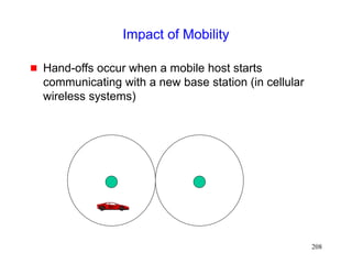
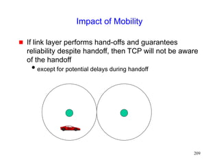
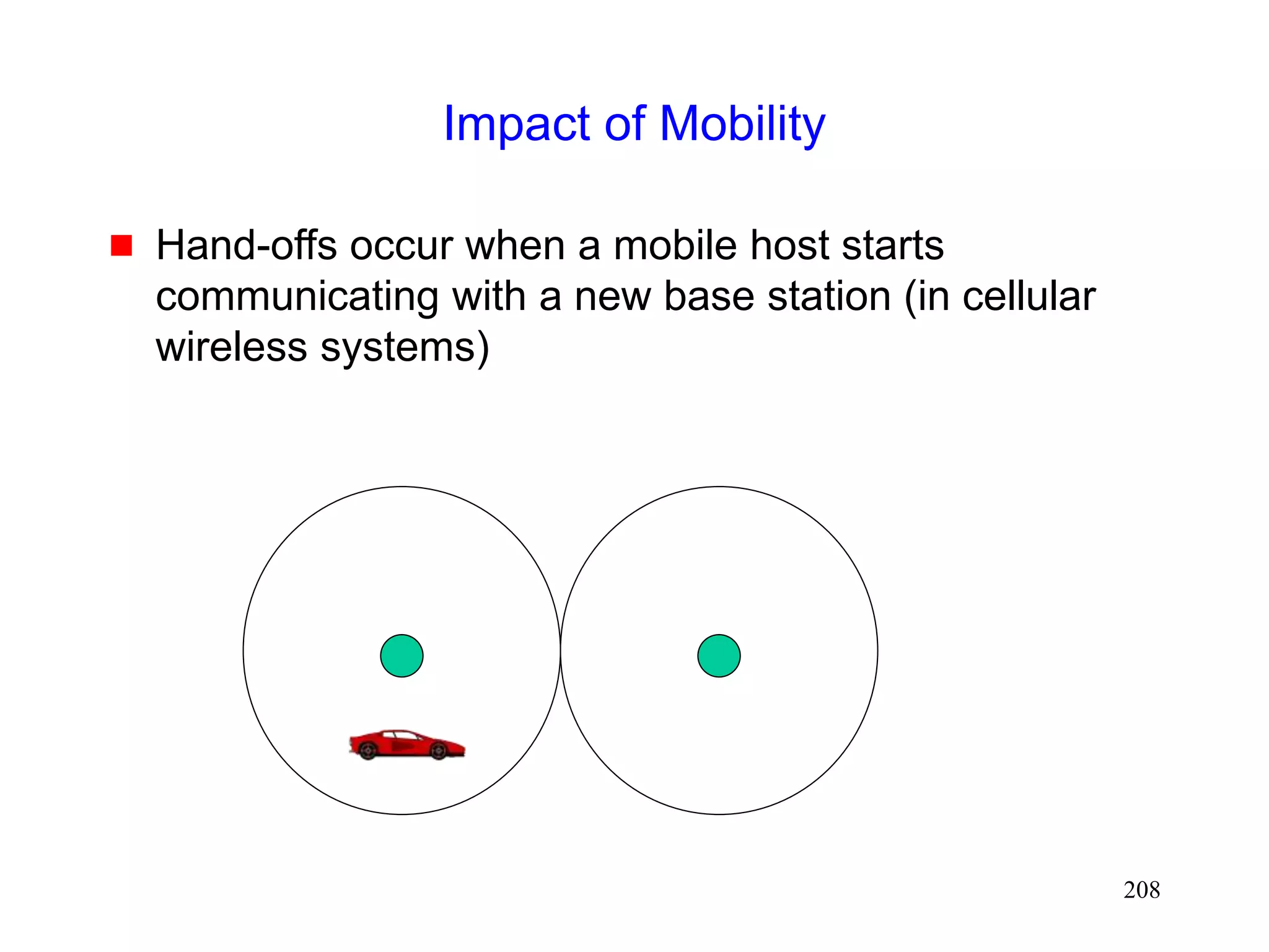
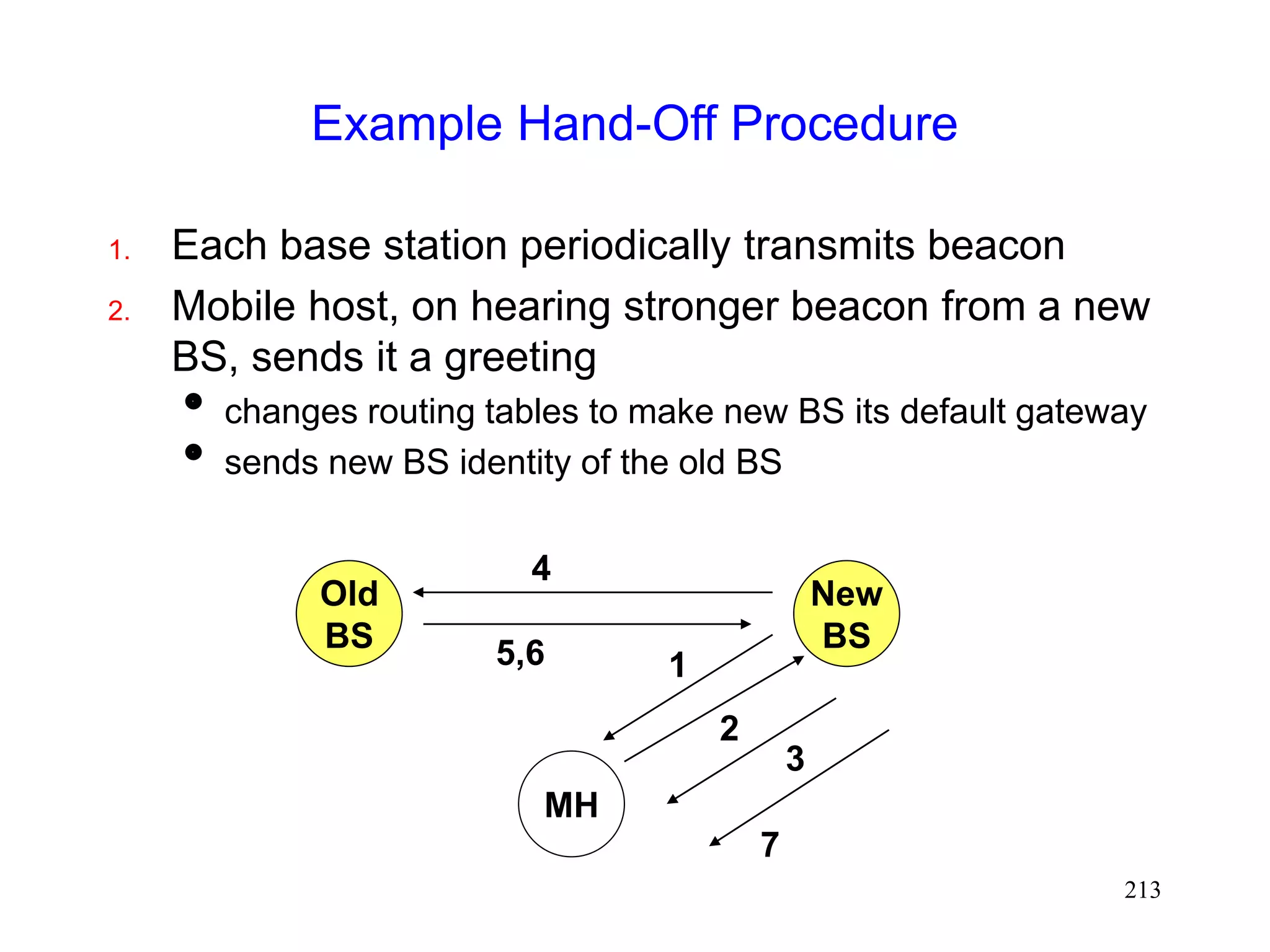
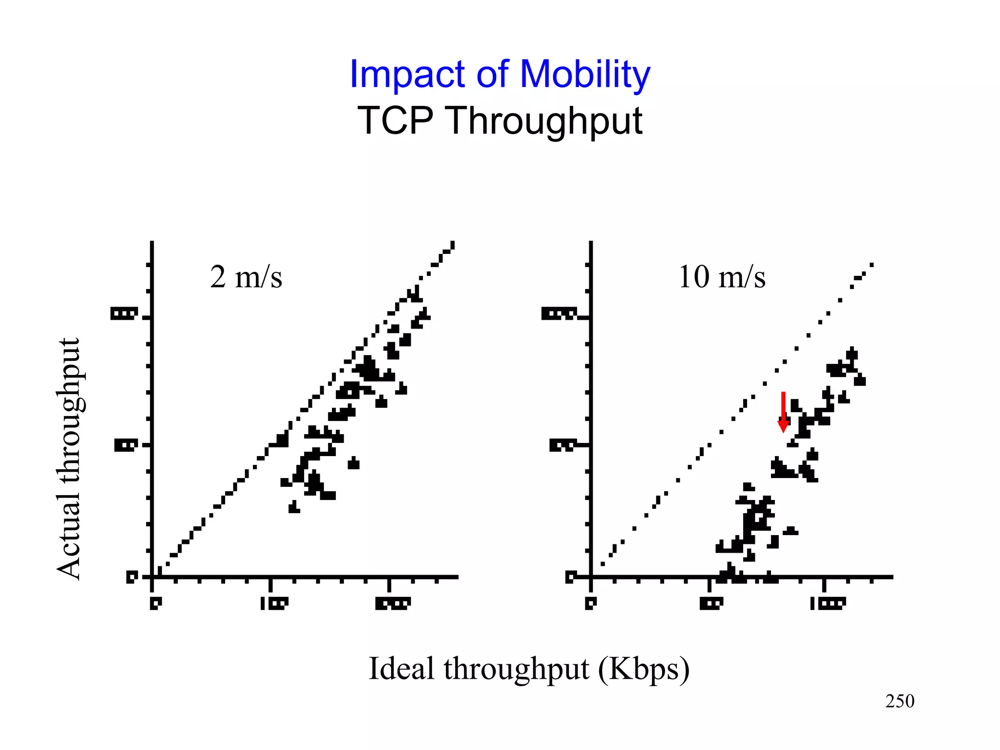
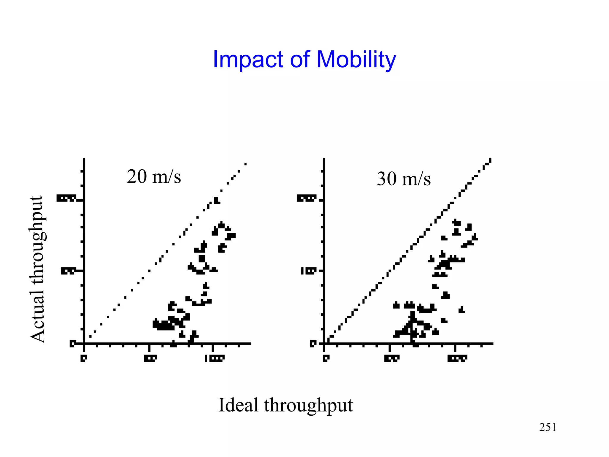
Impact of Mobility
If hand-off visible to IP
Need Mobile IP [Johnson96]
packets may be lost while a new route is being established
reliability despite handoff
We consider this case](https://image.slidesharecdn.com/tcp-wireless-tutorial-220913150100-d90cc118/85/tcp-wireless-tutorial-ppt-210-320.jpg)
![211
Mobile IP [Johnson96]
Router
1
Router
3
Router
2
S MH
Home
agent](https://image.slidesharecdn.com/tcp-wireless-tutorial-220913150100-d90cc118/85/tcp-wireless-tutorial-ppt-211-320.jpg)
![212
Mobile IP [Johnson96]
Router
1
Router
3
Router
2
S MH
Home agent
Foreign agent
move
Packets are tunneled
using IP in IP](https://image.slidesharecdn.com/tcp-wireless-tutorial-220913150100-d90cc118/85/tcp-wireless-tutorial-ppt-212-320.jpg)
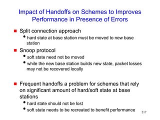
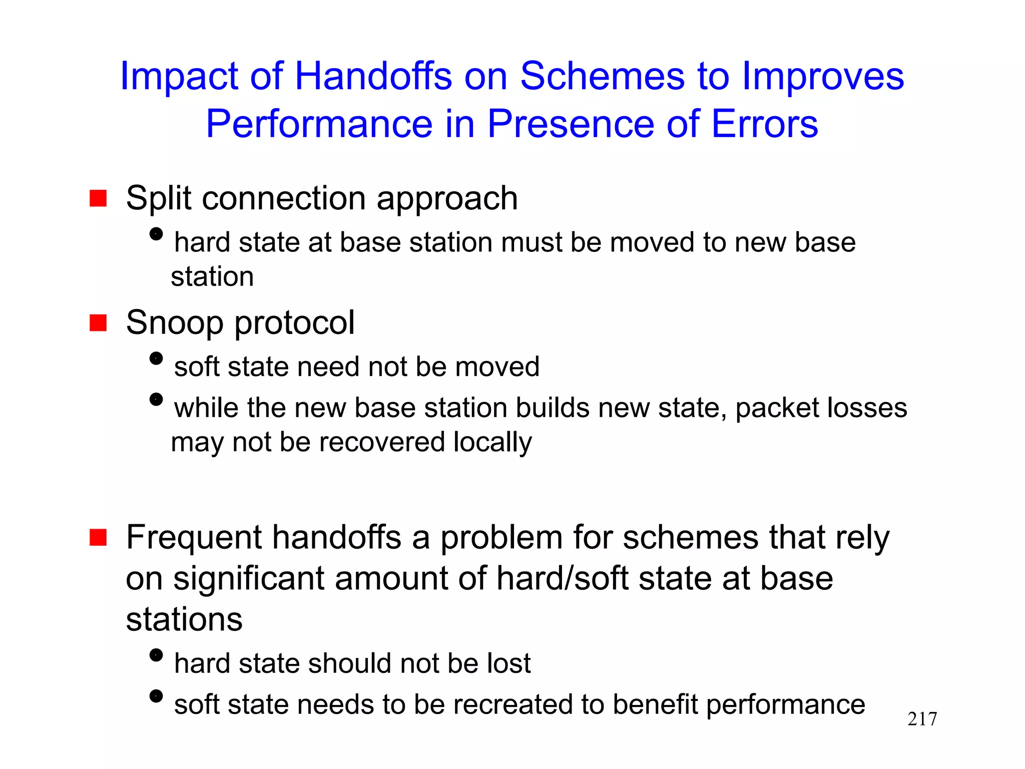
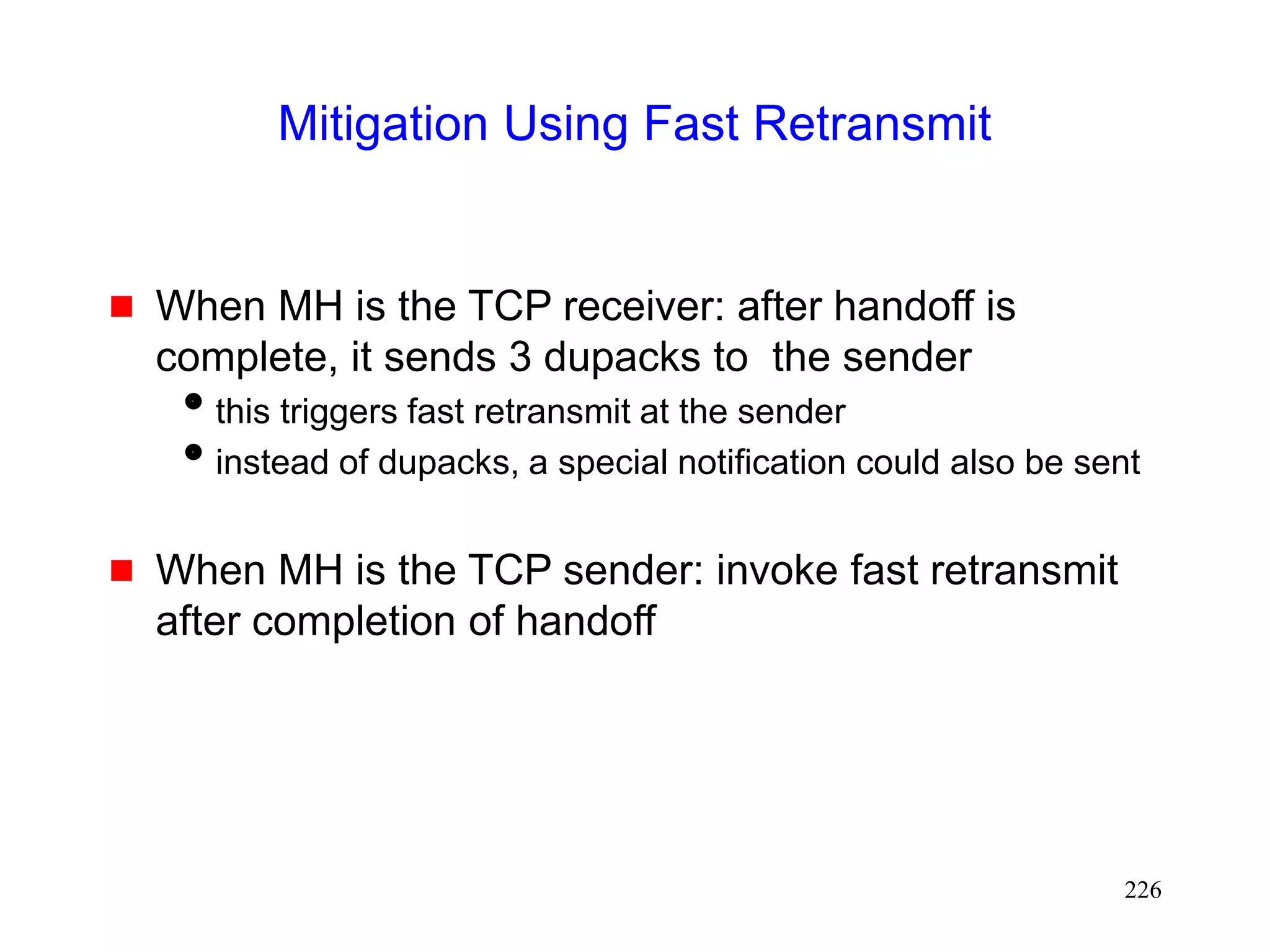
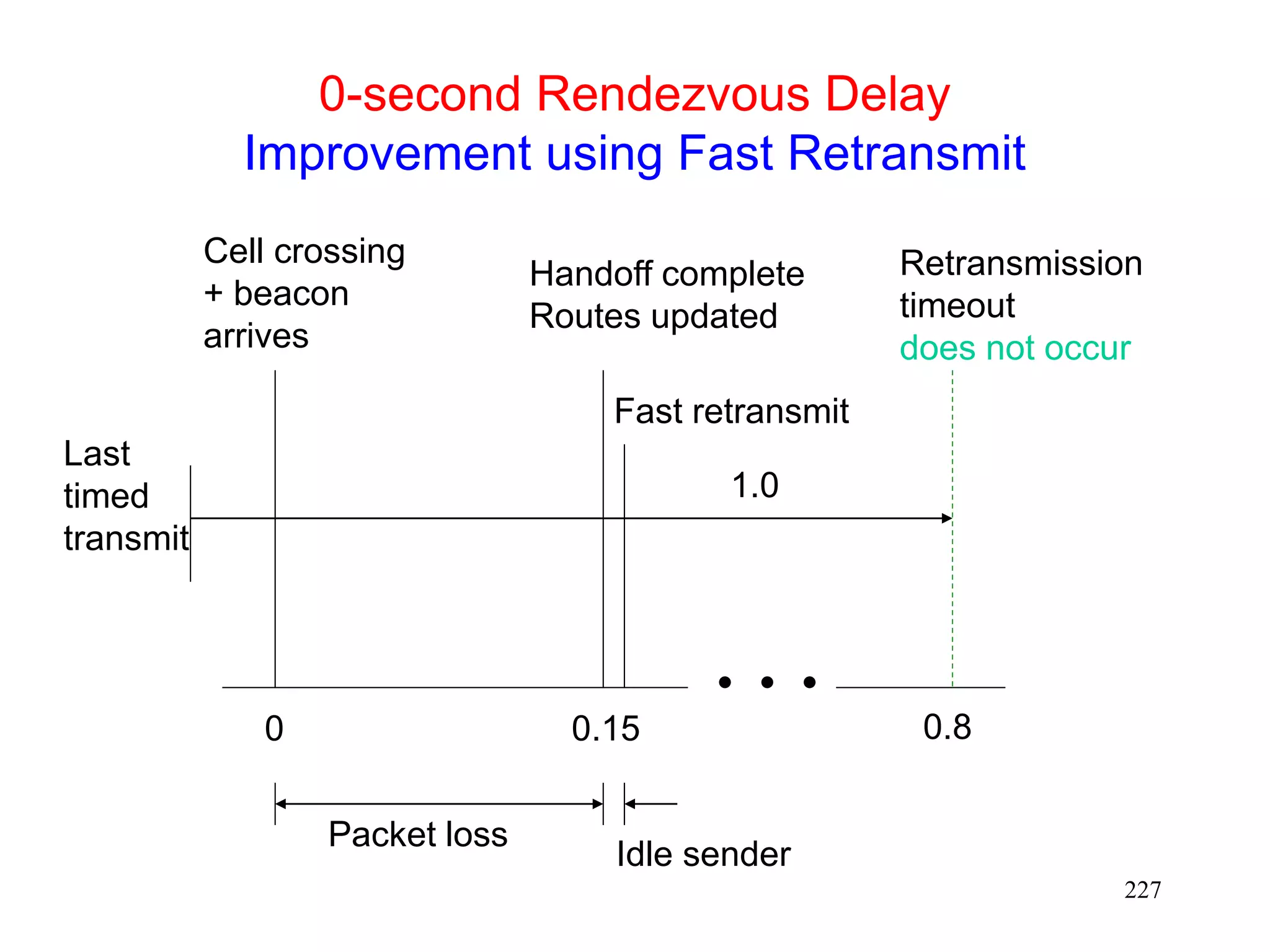
![220
Using Fast Retransmits to Recover from
Timeouts during Handoff [Caceres95]
During the long delay for a handoff to complete, a
whole window worth of data may be lost
After handoff is complete, acks are not received by
the TCP sender
Sender eventually times out, and retransmits
If handoff still not complete, another timeout will
occur
Performance penalty
Time wasted until timeout occurs
Window shrunk after timeout](https://image.slidesharecdn.com/tcp-wireless-tutorial-220913150100-d90cc118/85/tcp-wireless-tutorial-ppt-220-320.jpg)
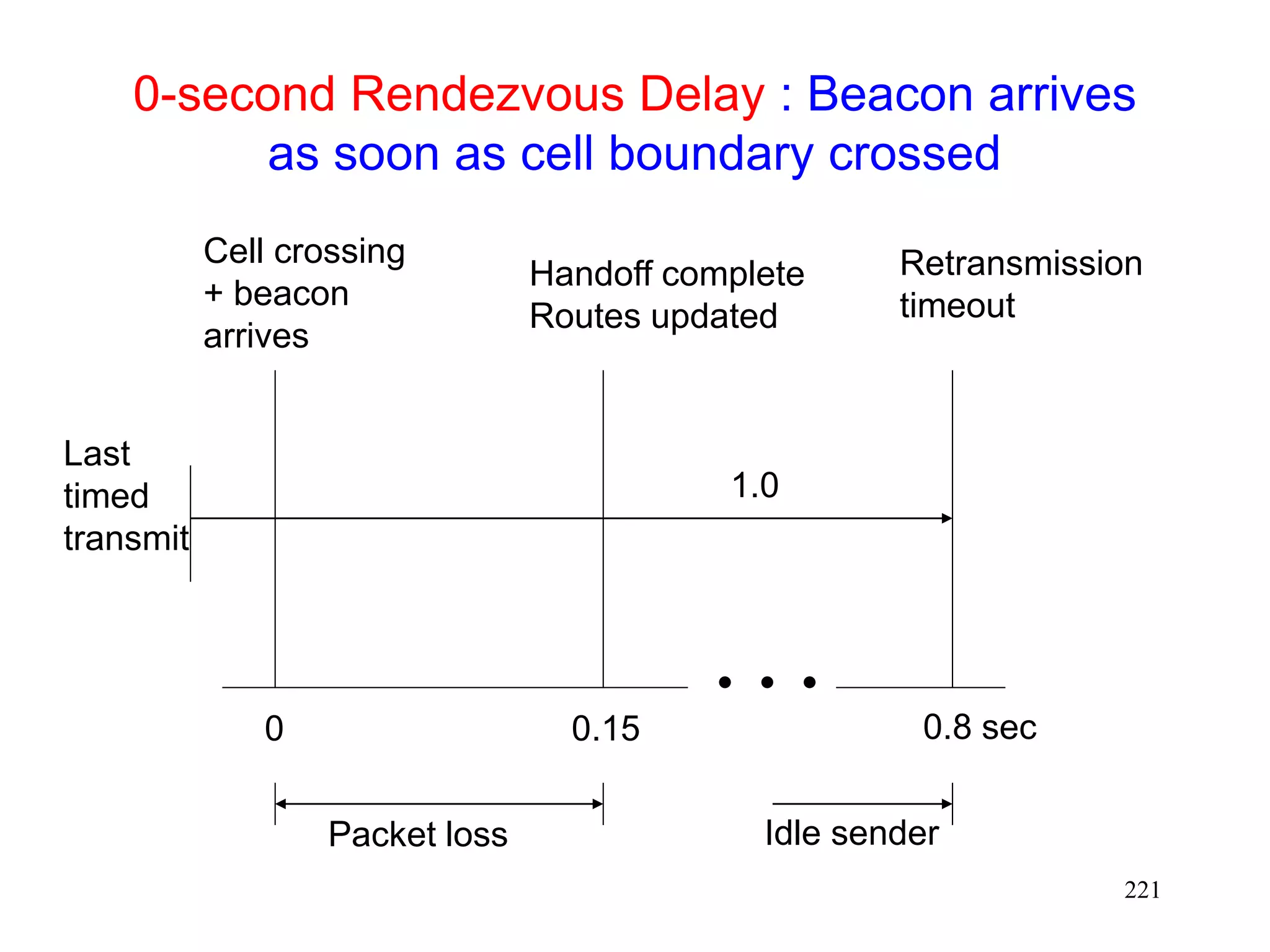
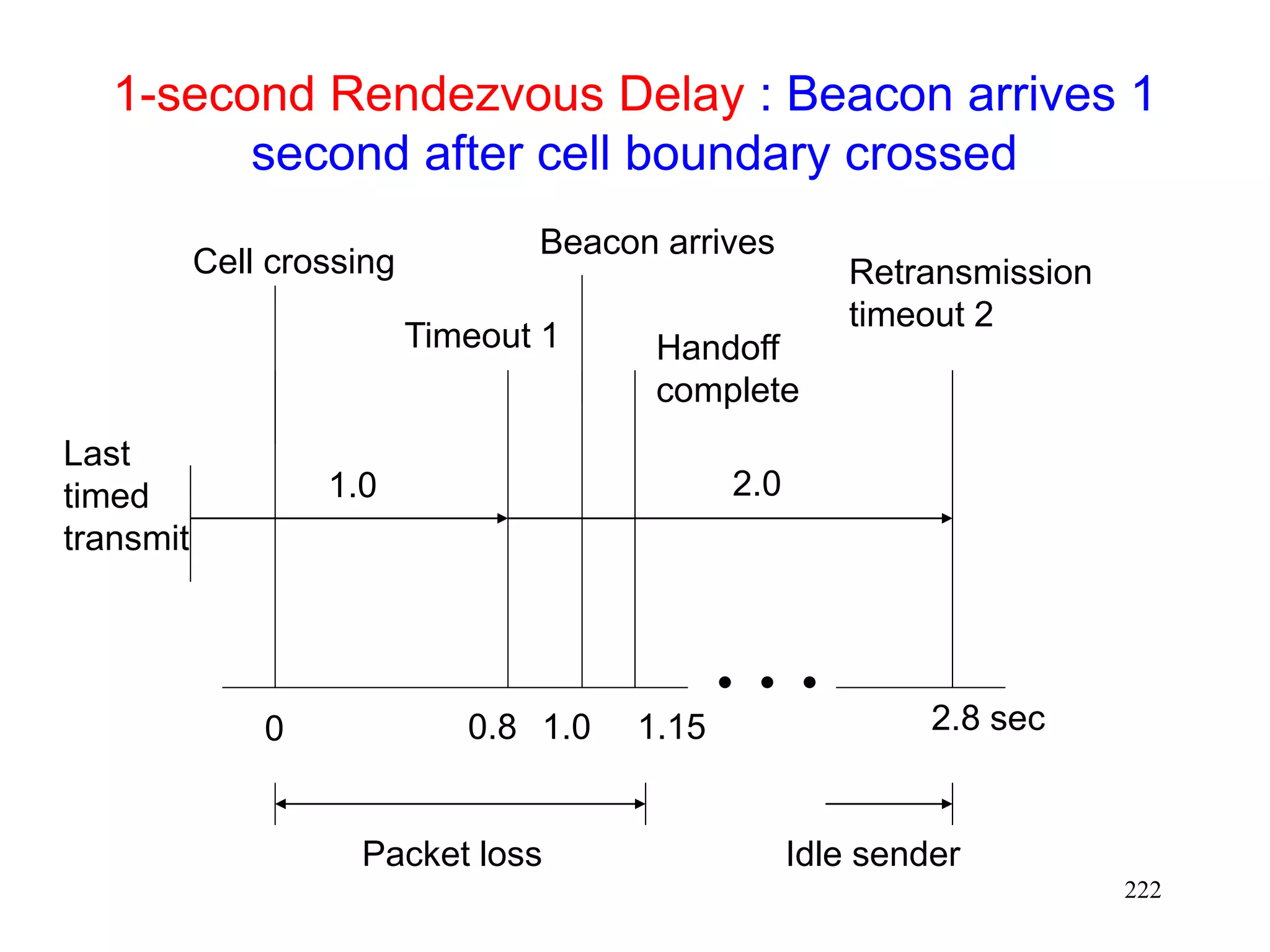
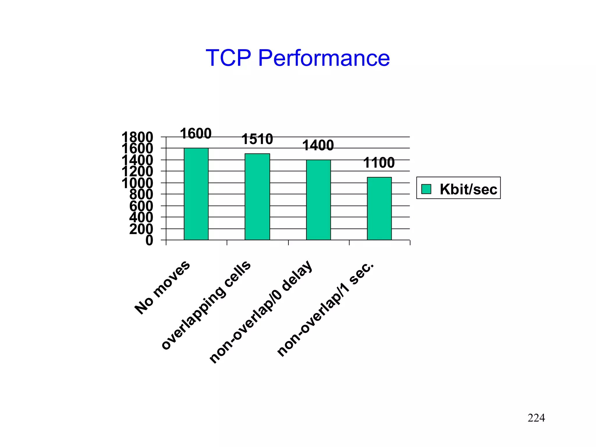
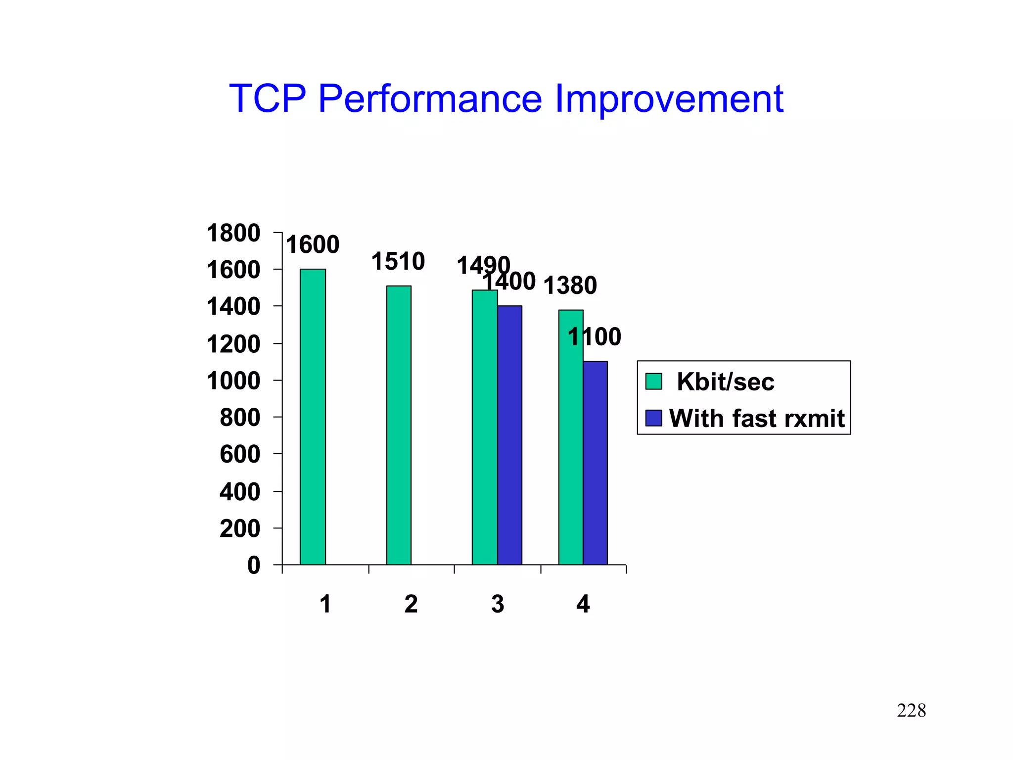
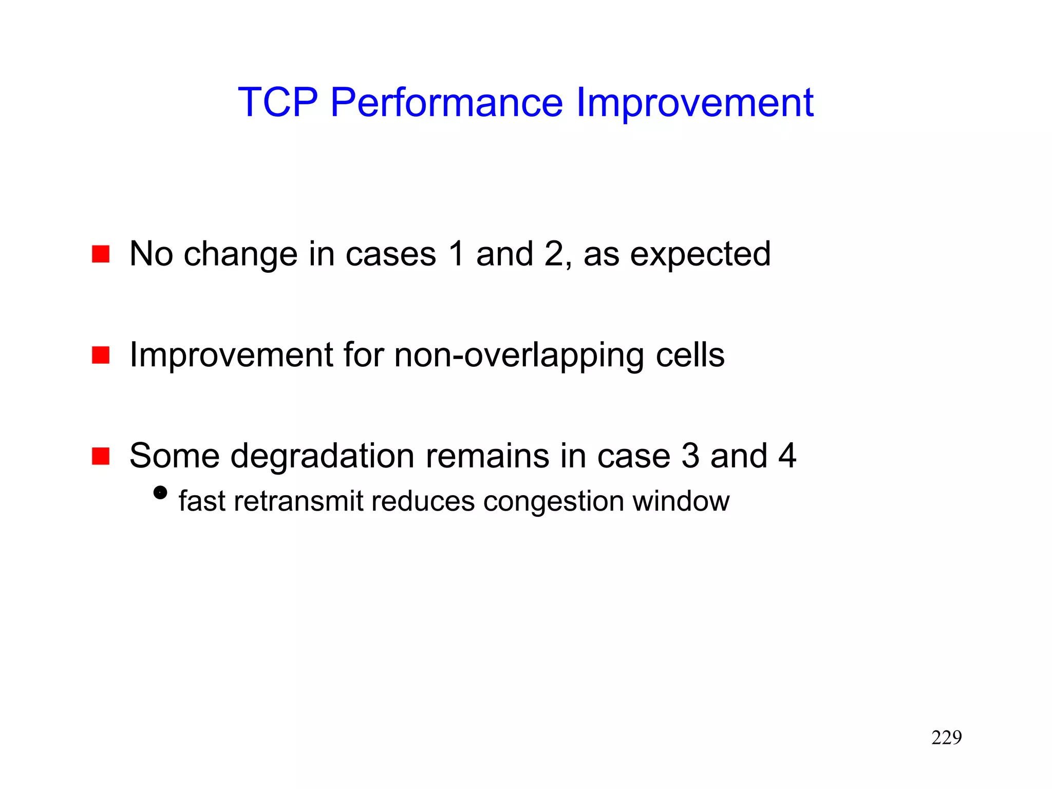
![223
Performance [Caceres95]
Four environments
1. No moves
2. Moves (once per 8 sec) between overlapping cells
3. Moves between non-overlapping cells, 0 sec delay
4. Moves between non-overlapping cells, 1 sec delay
Experiments using 2 Mbps WaveLan](https://image.slidesharecdn.com/tcp-wireless-tutorial-220913150100-d90cc118/85/tcp-wireless-tutorial-ppt-223-320.jpg)


![230
Improving Performance by Smooth Handoffs
[Caceres95]
Provide sufficient overlap between cells to avoid
packet loss
or
Buffer packets at BS
Discard the packets after a short interval
If handoff occurs before the interval expires, forward the
packets to the new base station
Prevents packet loss on handoff](https://image.slidesharecdn.com/tcp-wireless-tutorial-220913150100-d90cc118/85/tcp-wireless-tutorial-ppt-230-320.jpg)
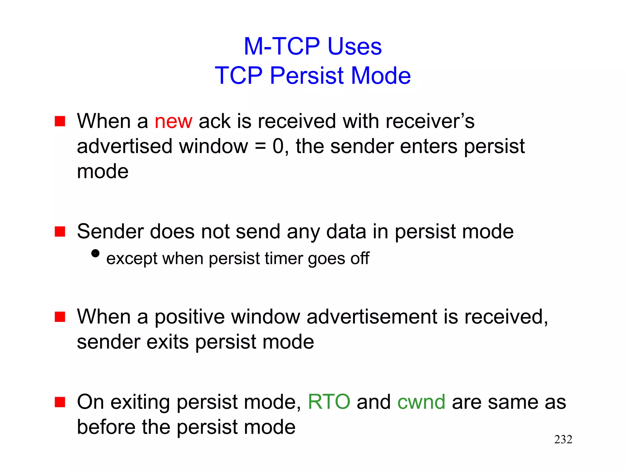
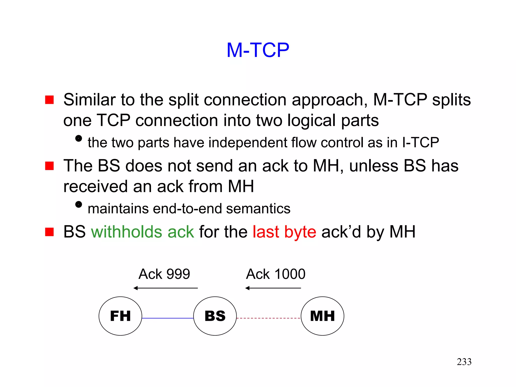
![231
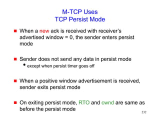
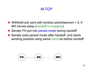
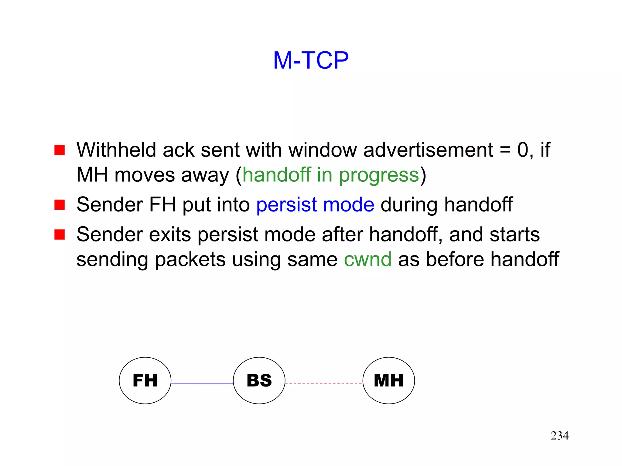
M-TCP [Brown97]
In the fast retransmit scheme [Caceres95]
sender starts transmitting soon after handoff
BUT congestion window shrinks
M-TCP attempts to avoid shrinkage in the
congestion window](https://image.slidesharecdn.com/tcp-wireless-tutorial-220913150100-d90cc118/85/tcp-wireless-tutorial-ppt-231-320.jpg)


![237
FreezeTCP [Goff99]
M-TCP needs help from base station
Base station withholds ack for one byte
The base station uses this ack to send a zero window
advertisement when a mobile host moves to another cell
FreezeTCP requires the receiver to send zero
window advertisement (ZWA)
FH MH
BS
Mobile
TCP receiver](https://image.slidesharecdn.com/tcp-wireless-tutorial-220913150100-d90cc118/85/tcp-wireless-tutorial-ppt-237-320.jpg)
![238
FreezeTCP [Goff99]
TCP receiver determines if a handoff is about to
happen
determination may be based on signal strength
Ideally, receiver should attempt to send ZWA
1 RTT before handoff
Receiver sends 3 dupacks when route is
reestablished
No help needed from the base station
an end-to-end enhancement
FH MH
BS
Mobile
TCP receiver](https://image.slidesharecdn.com/tcp-wireless-tutorial-220913150100-d90cc118/85/tcp-wireless-tutorial-ppt-238-320.jpg)
![239
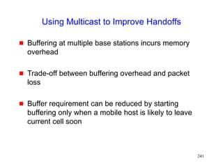
Using Multicast to Improve Handoffs
[Ghai94,Seshan96]
Define a group of base stations including
current cell of a mobile host
cells that the mobile host is likely to visit next
Address packets destined to the mobile host to the
group
Only one base station transmits the packets to the
mobile host
if rest of them buffer the packets, then packet loss minimized
on handoff](https://image.slidesharecdn.com/tcp-wireless-tutorial-220913150100-d90cc118/85/tcp-wireless-tutorial-ppt-239-320.jpg)
![240
Using Multicast to Improve Handoffs
Static group definition [Ghai94]
groups can be defined taking physical topology into account
static definition may not take individual user mobility pattern
into account
Dynamic group definition [Seshan96]
implemented using IP multicast groups
each user’s group can be different
overhead of updating the multicast groups is a concern with
a large scale deployment](https://image.slidesharecdn.com/tcp-wireless-tutorial-220913150100-d90cc118/85/tcp-wireless-tutorial-ppt-240-320.jpg)

![245
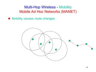
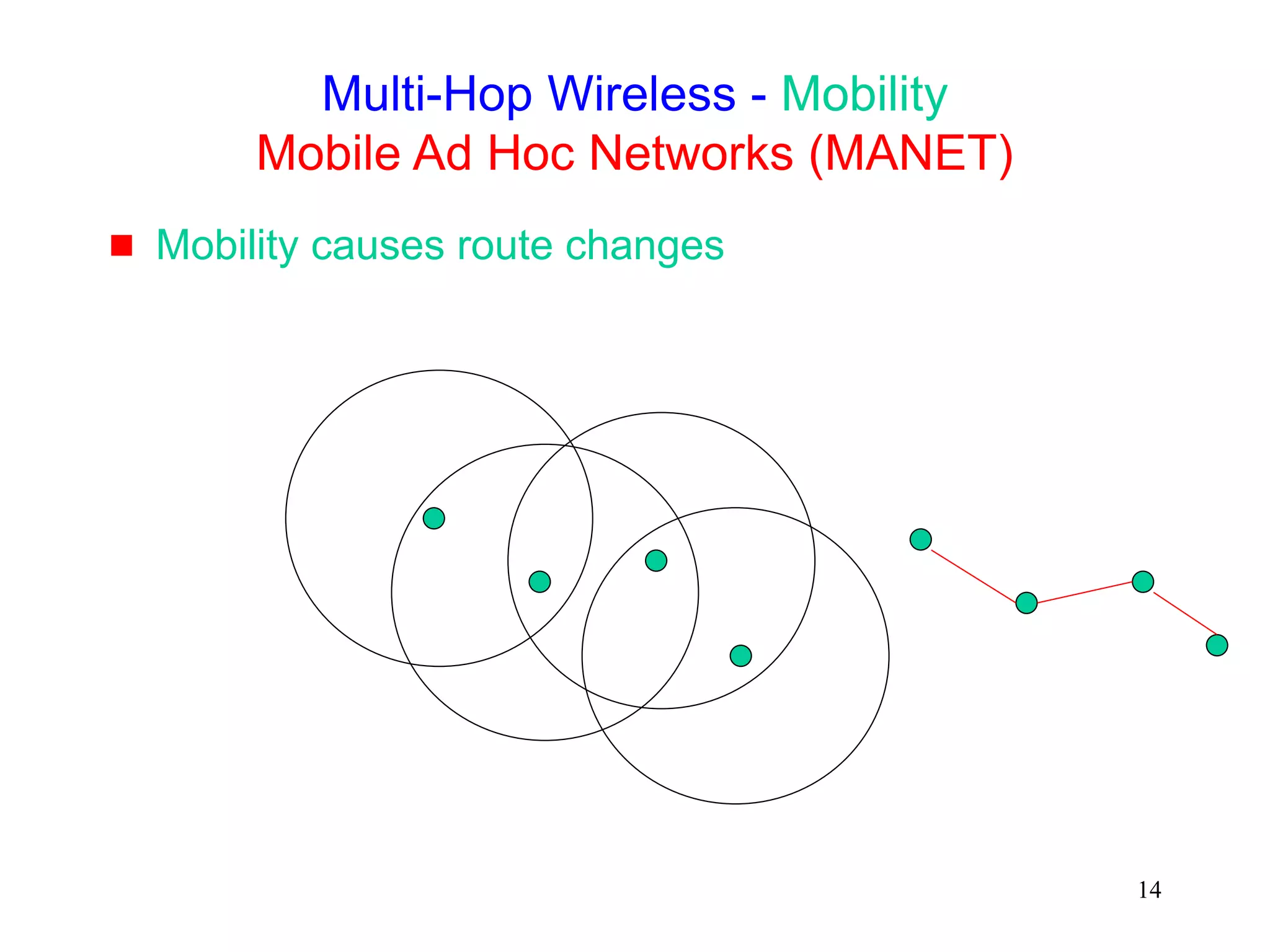
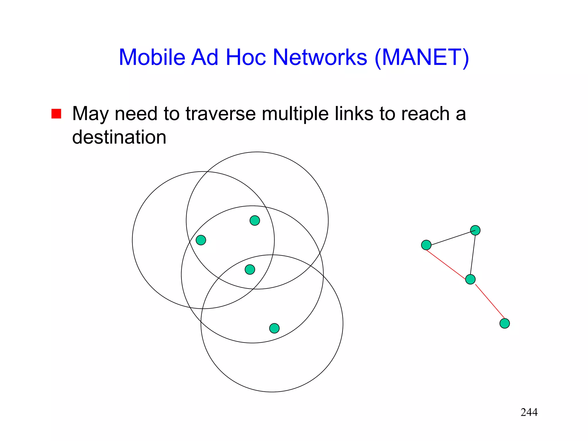
Mobile Ad Hoc Networks
[IETF-MANET]
Mobility causes route changes](https://image.slidesharecdn.com/tcp-wireless-tutorial-220913150100-d90cc118/85/tcp-wireless-tutorial-ppt-245-320.jpg)
![247
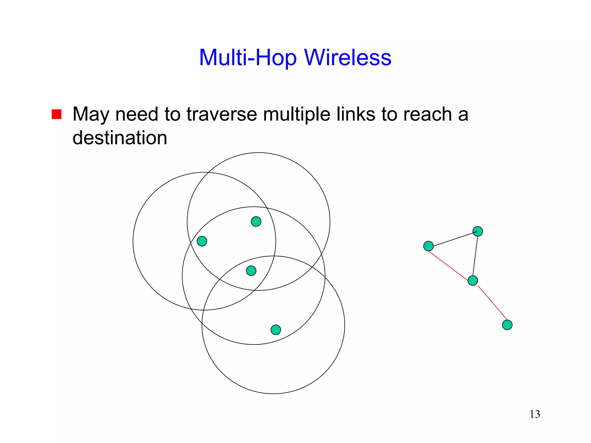
Throughput over Multi-Hop Wireless Paths
[Gerla99]
When contention-based MAC protocol is used,
connections over multiple hops are at a disadvantage
compared to shorter connections, because they
have to contend for wireless access at each hop
extent of packet delay or drop increases with number of
hops](https://image.slidesharecdn.com/tcp-wireless-tutorial-220913150100-d90cc118/85/tcp-wireless-tutorial-ppt-247-320.jpg)
![248
Impact of Multi-Hop Wireless Paths
[Holland99]
0
200
400
600
800
1000
1200
1400
1600
1 2 3 4 5 6 7 8 9 10
Number of hops
TCP
Throughtput
(Kbps)
TCP Throughput using 2 Mbps 802.11 MAC](https://image.slidesharecdn.com/tcp-wireless-tutorial-220913150100-d90cc118/85/tcp-wireless-tutorial-ppt-248-320.jpg)


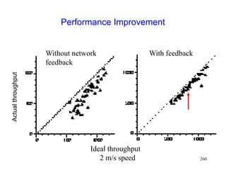
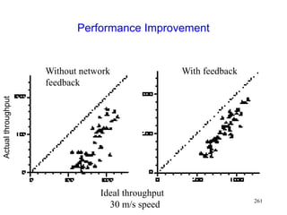
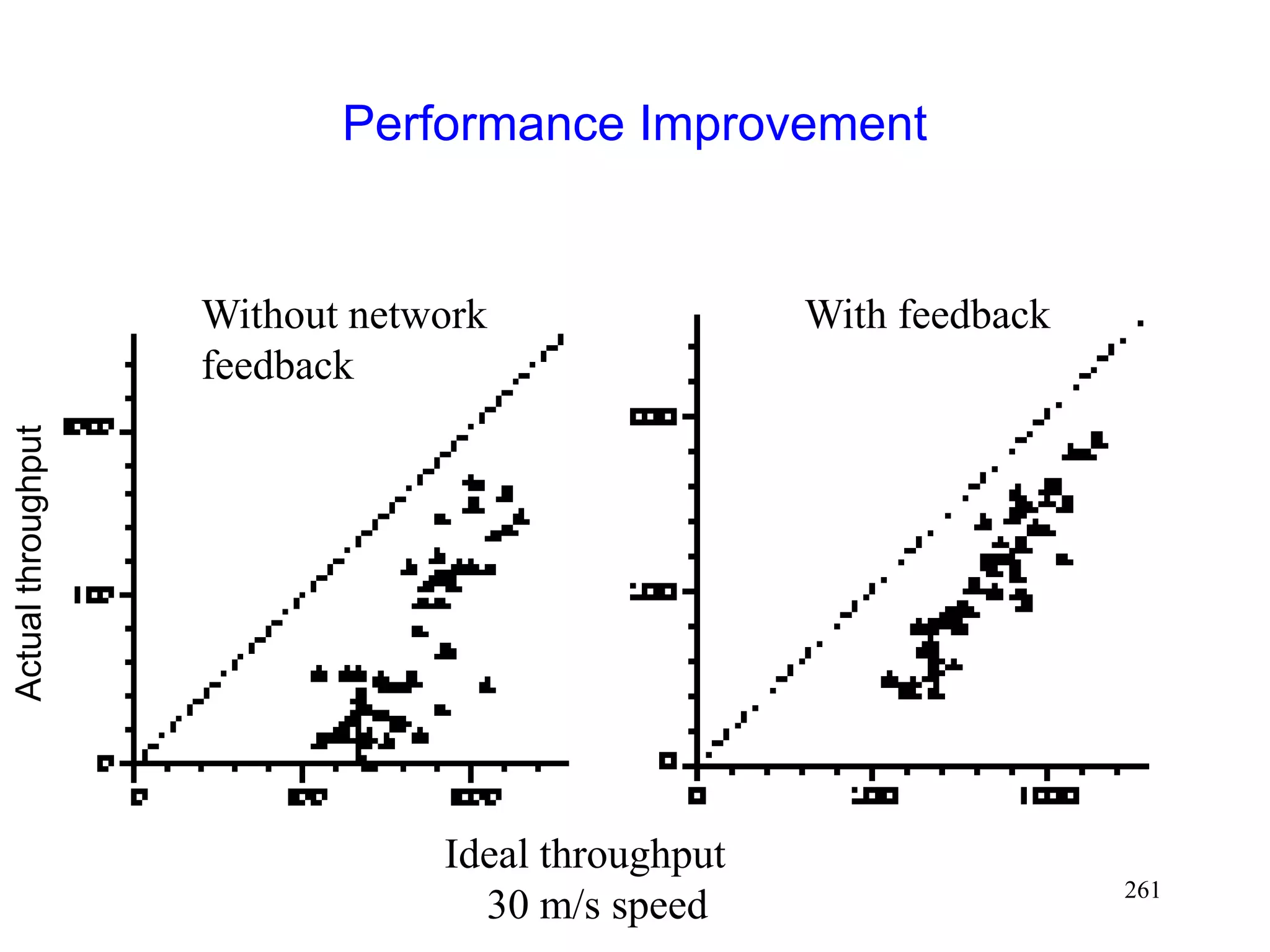
![262
Performance with Explicit Notification
[Holland99]
0
0.2
0.4
0.6
0.8
1
2 10 20 30
mean speed (m/s)
throughput
as
a
fraction
of
ideal
Base TCP
With explicit
notification](https://image.slidesharecdn.com/tcp-wireless-tutorial-220913150100-d90cc118/85/tcp-wireless-tutorial-ppt-262-320.jpg)
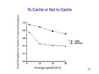
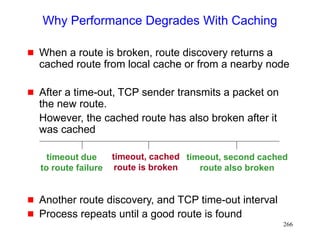
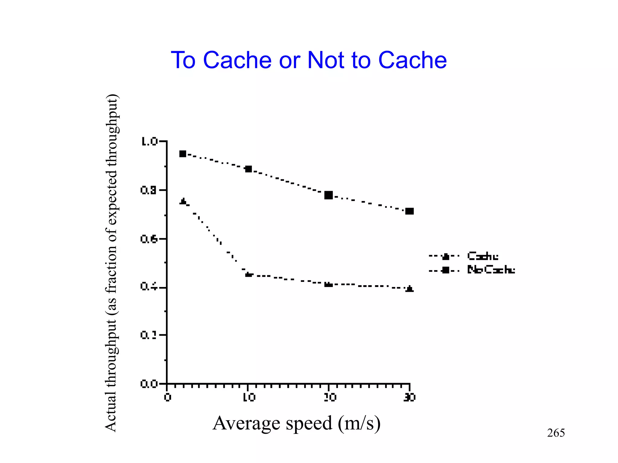
![264
Impact of Caching
Route caching has been suggested as a mechanism
to reduce route discovery overhead [Broch98]
Each node may cache one or more routes to a given
destination
When a route from S to D is detected as broken,
node S may:
Use another cached route from local cache, or
Obtain a new route using cached route at another node](https://image.slidesharecdn.com/tcp-wireless-tutorial-220913150100-d90cc118/85/tcp-wireless-tutorial-ppt-264-320.jpg)

![272
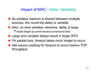
Impact of MAC - Delay Variability
[Balakrishnan97]
Several techniques may be used to mitigate problem,
based on minimizing ack transmissions
to reduce frequency of send-receive turnaround and
contention between acks and data
Piggybacking link layer acks with data
Sending fewer TCP acks - ack every d-th packet (d
may be chosen dynamically)
• but need to use rate control at sender to reduce
burstiness (for large d)
Ack filtering - Gateway may drop an older ack in the
queue, if a new ack arrives
reduces number of acks that need to be delivered to the
sender](https://image.slidesharecdn.com/tcp-wireless-tutorial-220913150100-d90cc118/85/tcp-wireless-tutorial-ppt-272-320.jpg)

![275
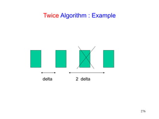
Header Compression for Wireless Networks
[Degermark96]
In TCP packet stream, most header bits are identical
Van Jacobson’s scheme exploits this observation to
compress headers, by only sending the “delta”
between the previous and current header
Packet losses result in inefficiency, as headers
cannot be reconstructed due to lost information
Packet losses likely on wireless links
[Degermark96] proposes a technique that works well
despite single packet loss
“twice” algorithm
if current packet fails TCP checksum, assume that a single
packet is lost
apply delta for the previous packet twice to the current
header, and test checksum again](https://image.slidesharecdn.com/tcp-wireless-tutorial-220913150100-d90cc118/85/tcp-wireless-tutorial-ppt-275-320.jpg)
![277
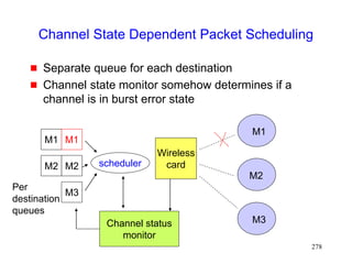
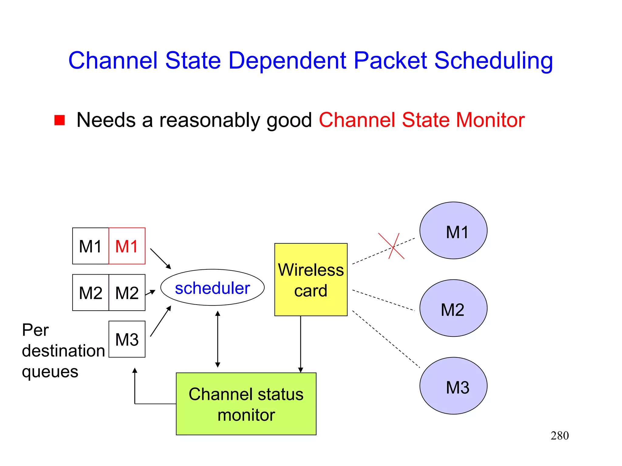
Channel State Dependent Packet Scheduling
[Bhagwat96]
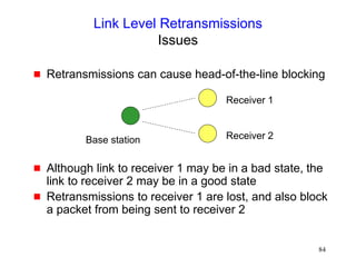
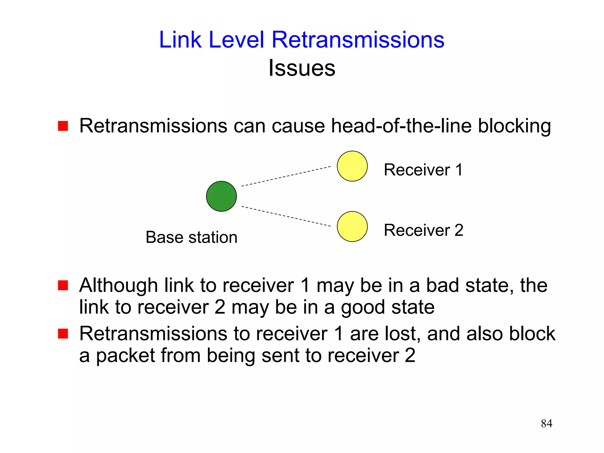
Head-of-the Line blocking can occur with FIFO (first-
in-first-out) scheduling, if sender attempts to
retransmit packets on a channel in a bad state
M1 M2 M3
M2 M1
Wireless
card
M1
M2
M3](https://image.slidesharecdn.com/tcp-wireless-tutorial-220913150100-d90cc118/85/tcp-wireless-tutorial-ppt-277-320.jpg)


![281
Automatic TCP Buffer Tuning [Semke98]
Using too small buffers can yield poor performance
Using too large buffers can limit number of open
connections
Automatic mechanisms to choose buffer size
dynamically would be useful](https://image.slidesharecdn.com/tcp-wireless-tutorial-220913150100-d90cc118/85/tcp-wireless-tutorial-ppt-281-320.jpg)


![2
Notes
Names in brackets, as in [Vaidya99], refer to a
document in the list of references
Many charts included in these slides are based on
similar results presented in graphs in published
literatures. Since, in many cases, exact numbers are
not provided in the papers, the charts in these slides
are based on “guess-timates” obtained from
published graphs. Please refer original sources for
accurate data.
This handout may not be as readable as the original
slides, since the slides contain colored text and
figures.](https://image.slidesharecdn.com/tcp-wireless-tutorial-220913150100-d90cc118/75/tcp-wireless-tutorial-ppt-2-2048.jpg)

![4
Internet Engineering Task Force (IETF)
Activities
IETF pilc (Performance Implications of Link
Characteristics) working group
http://www.ietf.org/html.charters/pilc-charter.html
http://pilc.grc.nasa.gov
Refer [Dawkins99] and [Montenegro99] for an overview of
related work
IETF tcpsat (TCP Over Satellite) working group
http://www.ietf.org/html.charters/tcpsat-charter.html
http://tcpsat.grc.nasa.gov/tcpsat/
Refer [Allman98] for overview of satellite related work](https://image.slidesharecdn.com/tcp-wireless-tutorial-220913150100-d90cc118/75/tcp-wireless-tutorial-ppt-4-2048.jpg)


![51
Fast Recovery
Fast recovery can result in a timeout with multiple
losses per RTT
.
TCP New-Reno [Hoe96]
stay in fast recovery until all packet losses in window are
recovered
can recover 1 packet loss per RTT without
causing a timeout
Selective Acknowledgements (SACK)
[mathis96rfc2018]
provides information about out-of-order packets received by
receiver
can recover multiple packet losses per RTT](https://image.slidesharecdn.com/tcp-wireless-tutorial-220913150100-d90cc118/75/tcp-wireless-tutorial-ppt-51-2048.jpg)

![61
Sometimes Congestion Response May be
Appropriate in Response to Errors
On a CDMA channel, errors occur due to interference
from other user, and due to noise [Karn99pilc]
Interference due to other users is an indication of
congestion. If such interference causes transmission errors,
it is appropriate to reduce congestion window
If noise causes errors, it is not appropriate to reduce window
When a channel is in a bad state for a long duration,
it might be better to let TCP backoff, so that it does
not unnecessarily attempt retransmissions while the
channel remains in the bad state
[Padmanabhan99pilc]](https://image.slidesharecdn.com/tcp-wireless-tutorial-220913150100-d90cc118/75/tcp-wireless-tutorial-ppt-61-2048.jpg)
![63
Impact of Random Errors [Vaidya99]
0
400000
800000
1200000
1600000
16384 32768 65536 131072
1/error rate (in bytes)
bits/sec
Exponential error model
2 Mbps wireless full duplex link
No congestion losses](https://image.slidesharecdn.com/tcp-wireless-tutorial-220913150100-d90cc118/75/tcp-wireless-tutorial-ppt-63-2048.jpg)


![76
Various Schemes
Link level mechanisms
Split connection approach
TCP-Aware link layer
TCP-Unaware approximation of TCP-aware link layer
Explicit notification
Receiver-based discrimination
Sender-based discrimination
For a brief overview, see [Dawkins99,Montenegro99]](https://image.slidesharecdn.com/tcp-wireless-tutorial-220913150100-d90cc118/75/tcp-wireless-tutorial-ppt-76-2048.jpg)

![78
Link Layer Mechanisms
Forward Error Correction
Forward Error Correction (FEC) [Lin83] can be use
to correct small number of errors
Correctable errors hidden from the TCP sender
FEC incurs overhead even when errors do not occur
Adaptive FEC schemes [Eckhardt98] can reduce the
overhead by choosing appropriate FEC dynamically](https://image.slidesharecdn.com/tcp-wireless-tutorial-220913150100-d90cc118/75/tcp-wireless-tutorial-ppt-78-2048.jpg)

![86
Link Level Retransmissions
An Early Study [DeSimone93]
The sender’s Retransmission Timeout (RTO) is a
function of measured RTT (round-trip times)
Link level retransmits increase RTT, therefore, RTO
If errors not frequent, RTO will not account for RTT
variations due to link level retransmissions
When errors occur, the sender may timeout & retransmit
before link level retransmission is successful
Sender and link layer both retransmit
Duplicate retransmissions (interference) waste wireless
bandwidth
Timeouts also result in reduced congestion window](https://image.slidesharecdn.com/tcp-wireless-tutorial-220913150100-d90cc118/75/tcp-wireless-tutorial-ppt-86-2048.jpg)
![88
A More Accurate Picture
Analysis in [DeSimone93] does not accurately model
real TCP stacks
With large RTO granularity, interference is unlikely, if
time required for link-level retransmission is small
compared to TCP RTO [Balakrishnan96Sigcomm]
Standard TCP RTO granularity is often large
Minimum RTO (2*granularity) is large enough to allow a
small number of link level retransmissions, if link level RTT is
relatively small
Interference due to timeout not a significant issue when
wireless RTT small, and RTO granularity large [Eckhardt98]](https://image.slidesharecdn.com/tcp-wireless-tutorial-220913150100-d90cc118/75/tcp-wireless-tutorial-ppt-88-2048.jpg)

![90
Link-Layer Retransmissions
A More Accurate Picture [Ludwig98]
Timeout interval may actually be larger than RTO
Retransmission timer reset on an ack
If the ack’d packet and next packet were transmitted in a
burst, next packet gets an additional RTT before the timer
will go off
1 2
data ack
Timeout = RTO
Effectively, Timeout = RTT of packet 1 + RTO
Reset, Timeout = RTO](https://image.slidesharecdn.com/tcp-wireless-tutorial-220913150100-d90cc118/75/tcp-wireless-tutorial-ppt-90-2048.jpg)

![94
Link Level Retransmissions
In-order delivery
Not all connections benefit from retransmissions or
ordered delivery
audio
Need to be able to specify requirements on a per-
packet basis [Ludwig99]
Should the packet be retransmitted? How many times?
Enforce in-order delivery?
Need a standard mechanism to specify the
requirements
open issue (IETF PILC working group)](https://image.slidesharecdn.com/tcp-wireless-tutorial-220913150100-d90cc118/75/tcp-wireless-tutorial-ppt-94-2048.jpg)
![95
Adaptive Link Layer Strategies
[Lettieri98,Eckhardt98,Zorzi97]
Adaptive protocols attempt to dynamically choose:
FEC code
retransmission limit
frame size](https://image.slidesharecdn.com/tcp-wireless-tutorial-220913150100-d90cc118/75/tcp-wireless-tutorial-ppt-95-2048.jpg)
![96
Link Layer Retransmissions [Vaidya99]
0
400000
800000
1200000
1600000
2000000
16384
32768
65536
1E+05
1/error rate (in bytes)
base TCP
Link layer
retransmission
2 Mbps wireless duplex link with 1 ms delay
Exponential error model
No congestion losses
20 ms 1 ms
10 Mbps 2 Mbps](https://image.slidesharecdn.com/tcp-wireless-tutorial-220913150100-d90cc118/75/tcp-wireless-tutorial-ppt-96-2048.jpg)


![105
Split Connection Approach
Indirect TCP [Bakre95,Bakre97]
FH - BS connection : Standard TCP
BS - MH connection : Standard TCP](https://image.slidesharecdn.com/tcp-wireless-tutorial-220913150100-d90cc118/75/tcp-wireless-tutorial-ppt-105-2048.jpg)
![106
Split Connection Approach
Selective Repeat Protocol (SRP) [Yavatkar94]
FH - BS connection : standard TCP
BS - FH connection : selective repeat protocol on top
of UDP
Performance better than Indirect-TCP (I-TCP),
because wireless portion of the connection can be
tuned to wireless behavior](https://image.slidesharecdn.com/tcp-wireless-tutorial-220913150100-d90cc118/75/tcp-wireless-tutorial-ppt-106-2048.jpg)
![107
Split Connection Approach : Other Variations
Asymmetric transport protocol (Mobile-TCP)
[Haas97icc]
Low overhead protocol at wireless hosts, and higher
overhead protocol at wired hosts
smaller headers used on wireless hop (header compression)
simpler flow control - on/off for MH to BS transfer
MH only does error detection, BS does error correction too
No congestion control over wireless hop](https://image.slidesharecdn.com/tcp-wireless-tutorial-220913150100-d90cc118/75/tcp-wireless-tutorial-ppt-107-2048.jpg)
![108
Split Connection Approach : Other Variations
Mobile-End Transport Protocol [Wang98infocom]
Terminate the TCP connection at BS
TCP connection runs only between BS and FH
BS pretends to be MH (MH’s IP functionality moved
to BS)
BS guarantees reliable ordered delivery of packets to
MH
BS-MH link can use any arbitrary protocol optimized
for wireless link
Idea similar to [Yavatkar94]](https://image.slidesharecdn.com/tcp-wireless-tutorial-220913150100-d90cc118/75/tcp-wireless-tutorial-ppt-108-2048.jpg)


![118
Snoop Protocol [Balakrishnan95acm]
Retains local recovery of Split Connection approach
and link level retransmission schemes
Improves on split connection
end-to-end semantics retained
soft state at base station, instead of hard state](https://image.slidesharecdn.com/tcp-wireless-tutorial-220913150100-d90cc118/75/tcp-wireless-tutorial-ppt-118-2048.jpg)

![130
Snoop [Balakrishnan95acm]
0
400000
800000
1200000
1600000
2000000
16K
32K
64K
128K
256K
no
error
1/error rate (in bytes)
bits/sec
base TCP
Snoop
2 Mbps Wireless link](https://image.slidesharecdn.com/tcp-wireless-tutorial-220913150100-d90cc118/75/tcp-wireless-tutorial-ppt-130-2048.jpg)
![135
WTCP Protocol [Ratnam98]
Snoop hides wireless losses from the sender
But sender’s RTT estimates may be larger in
presence of errors
Larger RTO results in slower response for congestion
losses
FH MH
BS](https://image.slidesharecdn.com/tcp-wireless-tutorial-220913150100-d90cc118/75/tcp-wireless-tutorial-ppt-135-2048.jpg)
![141
Delayed Dupacks Protocol [Mehta98,Vaidya99]
Attempts to imitate Snoop, without making the base
station TCP-aware
Snoop implements two features at the base station
link layer retransmission
reducing interference between TCP and link layer
retransmissions (by dropping dupacks)
Delayed Dupacks implements the same two features
at BS : link layer retransmission
at MH : reducing interference between TCP and link layer
retransmissions (by delaying dupacks)](https://image.slidesharecdn.com/tcp-wireless-tutorial-220913150100-d90cc118/75/tcp-wireless-tutorial-ppt-141-2048.jpg)


![153
Delayed Dupacks [Vaidya99]
0
400000
800000
1200000
1600000
2000000
16384
32768
65536
1E+05
1/error rate (in bytes)
base TCP
dupack delay
80ms + LL
Retransmit
Only LL
retransmit
2 Mbps wireless duplex link with 20 ms delay
No congestion losses
20 ms 20 ms
10 Mbps 2 Mbps](https://image.slidesharecdn.com/tcp-wireless-tutorial-220913150100-d90cc118/75/tcp-wireless-tutorial-ppt-153-2048.jpg)
![154
Delayed Dupacks [Vaidya99]
0
20000
40000
60000
80000
100000
120000
140000
160000
16384
32768
65536
1E+05
1/error rate (in bytes)
base TCP
dupack delay
80ms + LL
Retransmit
Only LL
retransmit
5% packet loss due to congestion
20 ms 20 ms
10 Mbps 2 Mbps](https://image.slidesharecdn.com/tcp-wireless-tutorial-220913150100-d90cc118/75/tcp-wireless-tutorial-ppt-154-2048.jpg)

![160
Explicit Notification Schemes
Motivated by the Explicit Congestion Notification
(ECN) proposals [Floyd94]
Variations proposed in literature differ in
who sends explicit notification
how they know to send the explicit notification
what the sender does on receiving the notification](https://image.slidesharecdn.com/tcp-wireless-tutorial-220913150100-d90cc118/75/tcp-wireless-tutorial-ppt-160-2048.jpg)
![163
Explicit Loss Notification [Balakrishnan98]
when MH is the TCP sender
Wireless link first on the path from sender to receiver
The base station keeps track of holes in the packet
sequence received from the sender
When a dupack is received from the receiver, the
base station compares the dupack sequence number
with the recorded holes
if there is a match, an ELN bit is set in the dupack
When sender receives dupack with ELN set, it
retransmits packet, but does not reduce congestion
window
MH FH
BS
4 3 2 1 1
3
4
wireless
Record
hole at 2
1
1
1 1
Dupack with ELN set](https://image.slidesharecdn.com/tcp-wireless-tutorial-220913150100-d90cc118/75/tcp-wireless-tutorial-ppt-163-2048.jpg)
![164
Explicit Bad State Notification [Bakshi97]
when MH is TCP receiver
Base station attempts to deliver packets to the MH
using a link layer retransmission scheme
If packet cannot be delivered using a small number of
retransmissions, BS sends a Explicit Bad State
Notification (EBSN) message to TCP sender
When TCP sender receives EBSN, it resets its timer
timeout delayed, when wireless channel in bad state](https://image.slidesharecdn.com/tcp-wireless-tutorial-220913150100-d90cc118/75/tcp-wireless-tutorial-ppt-164-2048.jpg)
![165
Partial Ack Protocols
[Cobb95][Biaz97]
Send two types of acknowledgements
A partial acknowledgement informs the sender that a
packet was received by an intermediate host
(typically, base station)
Normal TCP cumulative ack needed by the sender for
reliability purposes](https://image.slidesharecdn.com/tcp-wireless-tutorial-220913150100-d90cc118/75/tcp-wireless-tutorial-ppt-165-2048.jpg)
![168
Explicit Loss Notification [Biaz99thesis]
when MH is TCP receiver
Attempts to approximate hypothetical ELN proposed
in [Balakrishnan96] for the case when MH is receiver
Caches TCP sequence numbers at base station,
similar to Snoop. But does not cache data packets,
unlike Snoop.
Duplicate acks are tagged with ELN bit before being
forwarded to sender if sequence number for the lost
packet is cached at the base station
Sender takes appropriate action on receiving ELN](https://image.slidesharecdn.com/tcp-wireless-tutorial-220913150100-d90cc118/75/tcp-wireless-tutorial-ppt-168-2048.jpg)
![169
Explicit Loss Notification [Biaz99thesis]
when MH is TCP receiver
37
36
37
38
39
39
38
Sequence numbers
cached at base station
37 37
Dupack with ELN](https://image.slidesharecdn.com/tcp-wireless-tutorial-220913150100-d90cc118/75/tcp-wireless-tutorial-ppt-169-2048.jpg)
![172
Receiver-Based Scheme [Biaz98Asset]
MH is TCP receiver
Receiver uses a heuristic to guess cause of packet
loss
When receiver believes that packet loss is due to
errors, it sends a notification to the TCP sender
TCP sender, on receiving the notification, retransmits
the lost packet, but does not reduce congestion
window](https://image.slidesharecdn.com/tcp-wireless-tutorial-220913150100-d90cc118/75/tcp-wireless-tutorial-ppt-172-2048.jpg)
![176
Receiver-Based Scheme
Diagnostic Accuracy [Biaz99Asset]
Congestion losses Error losses](https://image.slidesharecdn.com/tcp-wireless-tutorial-220913150100-d90cc118/75/tcp-wireless-tutorial-ppt-176-2048.jpg)
![181
Sender-Based Discrimination Scheme
[Biaz98ic3n,Biaz99techrep]
Sender can attempt to determine cause of a packet
loss
If packet loss determined to be due to errors, do not
reduce congestion window
Sender can only use statistics based on round-trip
times, window sizes, and loss pattern
unless network provides more information (example: explicit
loss notification)](https://image.slidesharecdn.com/tcp-wireless-tutorial-220913150100-d90cc118/75/tcp-wireless-tutorial-ppt-181-2048.jpg)
![184
Heuristics for Congestion Avoidance
Some proposals
Normalized Delay Gradient [jain89]
r = [RTT(i)-RTT(i-1)] / [RTT(i)+RTT(i-1)]
w = [W(i)-W(i-1)] / [W(i)+W(i-1)]
Condition C = (r/w > 0)](https://image.slidesharecdn.com/tcp-wireless-tutorial-220913150100-d90cc118/75/tcp-wireless-tutorial-ppt-184-2048.jpg)
![185
Heuristics for Congestion Avoidance
Some proposals
Normalized Throughput Gradient [Wang91]
Throughput gradient
TG(i) = [T(i) - T(i-1) ] / [ W(i)-W(i-1)]
Normalized Throughout Gradient
NTG = TG(i) / TG(1)
Condition C = (NTG < 0.5)](https://image.slidesharecdn.com/tcp-wireless-tutorial-220913150100-d90cc118/75/tcp-wireless-tutorial-ppt-185-2048.jpg)
![186
Heuristics for Congestion Avoidance
Some proposals
TCP Vegas [Brakmo94]
expected throughput ET = W(i) / RTTmin
actual throughput AT = W(i) / RTT(i)
Condition C = ( ET-AT > beta)](https://image.slidesharecdn.com/tcp-wireless-tutorial-220913150100-d90cc118/75/tcp-wireless-tutorial-ppt-186-2048.jpg)
![188
Sender-Based Schemes
Diagnostic Accuracy [Biaz99ic3n]](https://image.slidesharecdn.com/tcp-wireless-tutorial-220913150100-d90cc118/75/tcp-wireless-tutorial-ppt-188-2048.jpg)
![189
Sender-Based Schemes
Diagnostic Accuracy [Biaz99ic3n]](https://image.slidesharecdn.com/tcp-wireless-tutorial-220913150100-d90cc118/75/tcp-wireless-tutorial-ppt-189-2048.jpg)


![199
Improving TCP-over-Satellite
[Allman98sept][IETF-TCPSAT]
Larger congestion window (window scale option)
maximum window size up to 2^30
Acknowledge every packet (do not delay acks)
Selective acks
fast recovery can only recover one packet loss per RTT
SACKS allow multiple packet recovery per RTT](https://image.slidesharecdn.com/tcp-wireless-tutorial-220913150100-d90cc118/75/tcp-wireless-tutorial-ppt-199-2048.jpg)
![200
Larger Initial Window
[Allman98september] [Allman98august]
Allows initial window size of cwnd to be up to
approximately 4 Kbyte
Larger initial window results in faster window growth
during slow start
avoids wait for delayed ack timers (which will occur with
cwnd = 1 MSS)
larger initial window requires fewer RTTs to reach ssthresh](https://image.slidesharecdn.com/tcp-wireless-tutorial-220913150100-d90cc118/75/tcp-wireless-tutorial-ppt-200-2048.jpg)
![201
Byte Counting [Allman98august]
Increase window by number of new bytes ack’d in an
acknowledgement, instead of 1 MSS per ack
Speeds up window growth despite delayed or lost
acks
Need to reduce bursts from sender
limiting size of window growth per ack
rate control](https://image.slidesharecdn.com/tcp-wireless-tutorial-220913150100-d90cc118/75/tcp-wireless-tutorial-ppt-201-2048.jpg)
![202
Space Communications Protocol Standard-
Transport Protocol (SCPS-TP) [Durst96]
Sender makes default assumption about source of
packet loss
default assumption can be set by network manager on a
per-route basis
default assumption can be changed due to explicit feedback
from the network
Congestion control algorithm derived from TCP-
Vegas, to bound window growth, to reduce
congestion-induced losses](https://image.slidesharecdn.com/tcp-wireless-tutorial-220913150100-d90cc118/75/tcp-wireless-tutorial-ppt-202-2048.jpg)
![204
Satellite Transport Protocol (STP)
[Henderson98]
Uses split connection approach
Protocol on satellite channel different from TCP
selective negative acks when receiver detects losses
no retransmission timer
transmitter periodically requests receiver to ack received
data
reduces reverse channel bandwidth usage when losses are
rare](https://image.slidesharecdn.com/tcp-wireless-tutorial-220913150100-d90cc118/75/tcp-wireless-tutorial-ppt-204-2048.jpg)
![205
Early Acks
Spoofing
Ground station acks packets
Should take responsibility for delivering packets
Early acks from ground station result in faster congestion
window growth
ACKprime approach [Scott98]
Acks from ground station only used to grow congestion
window
Reliable delivery assumed only on reception of an ack from
the receiver
• this is similar to the partial ack approach [Biaz97]](https://image.slidesharecdn.com/tcp-wireless-tutorial-220913150100-d90cc118/75/tcp-wireless-tutorial-ppt-205-2048.jpg)

![210
Impact of Mobility
If hand-off visible to IP
Need Mobile IP [Johnson96]
packets may be lost while a new route is being established
reliability despite handoff
We consider this case](https://image.slidesharecdn.com/tcp-wireless-tutorial-220913150100-d90cc118/75/tcp-wireless-tutorial-ppt-210-2048.jpg)
![211
Mobile IP [Johnson96]
Router
1
Router
3
Router
2
S MH
Home
agent](https://image.slidesharecdn.com/tcp-wireless-tutorial-220913150100-d90cc118/75/tcp-wireless-tutorial-ppt-211-2048.jpg)
![212
Mobile IP [Johnson96]
Router
1
Router
3
Router
2
S MH
Home agent
Foreign agent
move
Packets are tunneled
using IP in IP](https://image.slidesharecdn.com/tcp-wireless-tutorial-220913150100-d90cc118/75/tcp-wireless-tutorial-ppt-212-2048.jpg)


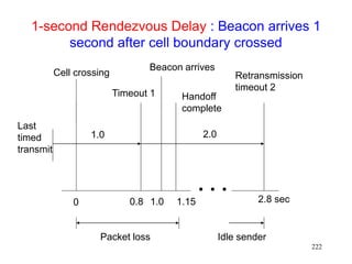
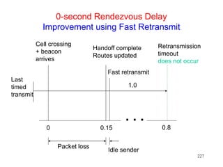
![220
Using Fast Retransmits to Recover from
Timeouts during Handoff [Caceres95]
During the long delay for a handoff to complete, a
whole window worth of data may be lost
After handoff is complete, acks are not received by
the TCP sender
Sender eventually times out, and retransmits
If handoff still not complete, another timeout will
occur
Performance penalty
Time wasted until timeout occurs
Window shrunk after timeout](https://image.slidesharecdn.com/tcp-wireless-tutorial-220913150100-d90cc118/75/tcp-wireless-tutorial-ppt-220-2048.jpg)
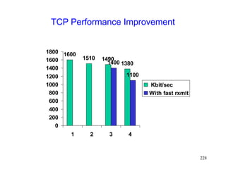
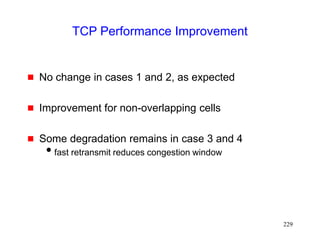
![223
Performance [Caceres95]
Four environments
1. No moves
2. Moves (once per 8 sec) between overlapping cells
3. Moves between non-overlapping cells, 0 sec delay
4. Moves between non-overlapping cells, 1 sec delay
Experiments using 2 Mbps WaveLan](https://image.slidesharecdn.com/tcp-wireless-tutorial-220913150100-d90cc118/75/tcp-wireless-tutorial-ppt-223-2048.jpg)
![230
Improving Performance by Smooth Handoffs
[Caceres95]
Provide sufficient overlap between cells to avoid
packet loss
or
Buffer packets at BS
Discard the packets after a short interval
If handoff occurs before the interval expires, forward the
packets to the new base station
Prevents packet loss on handoff](https://image.slidesharecdn.com/tcp-wireless-tutorial-220913150100-d90cc118/75/tcp-wireless-tutorial-ppt-230-2048.jpg)
![231
M-TCP [Brown97]
In the fast retransmit scheme [Caceres95]
sender starts transmitting soon after handoff
BUT congestion window shrinks
M-TCP attempts to avoid shrinkage in the
congestion window](https://image.slidesharecdn.com/tcp-wireless-tutorial-220913150100-d90cc118/75/tcp-wireless-tutorial-ppt-231-2048.jpg)
![237
FreezeTCP [Goff99]
M-TCP needs help from base station
Base station withholds ack for one byte
The base station uses this ack to send a zero window
advertisement when a mobile host moves to another cell
FreezeTCP requires the receiver to send zero
window advertisement (ZWA)
FH MH
BS
Mobile
TCP receiver](https://image.slidesharecdn.com/tcp-wireless-tutorial-220913150100-d90cc118/75/tcp-wireless-tutorial-ppt-237-2048.jpg)
![238
FreezeTCP [Goff99]
TCP receiver determines if a handoff is about to
happen
determination may be based on signal strength
Ideally, receiver should attempt to send ZWA
1 RTT before handoff
Receiver sends 3 dupacks when route is
reestablished
No help needed from the base station
an end-to-end enhancement
FH MH
BS
Mobile
TCP receiver](https://image.slidesharecdn.com/tcp-wireless-tutorial-220913150100-d90cc118/75/tcp-wireless-tutorial-ppt-238-2048.jpg)
![239
Using Multicast to Improve Handoffs
[Ghai94,Seshan96]
Define a group of base stations including
current cell of a mobile host
cells that the mobile host is likely to visit next
Address packets destined to the mobile host to the
group
Only one base station transmits the packets to the
mobile host
if rest of them buffer the packets, then packet loss minimized
on handoff](https://image.slidesharecdn.com/tcp-wireless-tutorial-220913150100-d90cc118/75/tcp-wireless-tutorial-ppt-239-2048.jpg)
![240
Using Multicast to Improve Handoffs
Static group definition [Ghai94]
groups can be defined taking physical topology into account
static definition may not take individual user mobility pattern
into account
Dynamic group definition [Seshan96]
implemented using IP multicast groups
each user’s group can be different
overhead of updating the multicast groups is a concern with
a large scale deployment](https://image.slidesharecdn.com/tcp-wireless-tutorial-220913150100-d90cc118/75/tcp-wireless-tutorial-ppt-240-2048.jpg)
![245
Mobile Ad Hoc Networks
[IETF-MANET]
Mobility causes route changes](https://image.slidesharecdn.com/tcp-wireless-tutorial-220913150100-d90cc118/75/tcp-wireless-tutorial-ppt-245-2048.jpg)
![247
Throughput over Multi-Hop Wireless Paths
[Gerla99]
When contention-based MAC protocol is used,
connections over multiple hops are at a disadvantage
compared to shorter connections, because they
have to contend for wireless access at each hop
extent of packet delay or drop increases with number of
hops](https://image.slidesharecdn.com/tcp-wireless-tutorial-220913150100-d90cc118/75/tcp-wireless-tutorial-ppt-247-2048.jpg)
![248
Impact of Multi-Hop Wireless Paths
[Holland99]
0
200
400
600
800
1000
1200
1400
1600
1 2 3 4 5 6 7 8 9 10
Number of hops
TCP
Throughtput
(Kbps)
TCP Throughput using 2 Mbps 802.11 MAC](https://image.slidesharecdn.com/tcp-wireless-tutorial-220913150100-d90cc118/75/tcp-wireless-tutorial-ppt-248-2048.jpg)
![262
Performance with Explicit Notification
[Holland99]
0
0.2
0.4
0.6
0.8
1
2 10 20 30
mean speed (m/s)
throughput
as
a
fraction
of
ideal
Base TCP
With explicit
notification](https://image.slidesharecdn.com/tcp-wireless-tutorial-220913150100-d90cc118/75/tcp-wireless-tutorial-ppt-262-2048.jpg)
![264
Impact of Caching
Route caching has been suggested as a mechanism
to reduce route discovery overhead [Broch98]
Each node may cache one or more routes to a given
destination
When a route from S to D is detected as broken,
node S may:
Use another cached route from local cache, or
Obtain a new route using cached route at another node](https://image.slidesharecdn.com/tcp-wireless-tutorial-220913150100-d90cc118/75/tcp-wireless-tutorial-ppt-264-2048.jpg)
![272
Impact of MAC - Delay Variability
[Balakrishnan97]
Several techniques may be used to mitigate problem,
based on minimizing ack transmissions
to reduce frequency of send-receive turnaround and
contention between acks and data
Piggybacking link layer acks with data
Sending fewer TCP acks - ack every d-th packet (d
may be chosen dynamically)
• but need to use rate control at sender to reduce
burstiness (for large d)
Ack filtering - Gateway may drop an older ack in the
queue, if a new ack arrives
reduces number of acks that need to be delivered to the
sender](https://image.slidesharecdn.com/tcp-wireless-tutorial-220913150100-d90cc118/75/tcp-wireless-tutorial-ppt-272-2048.jpg)

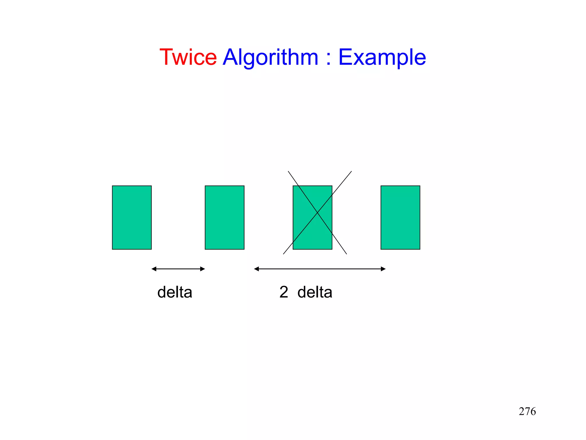
![275
Header Compression for Wireless Networks
[Degermark96]
In TCP packet stream, most header bits are identical
Van Jacobson’s scheme exploits this observation to
compress headers, by only sending the “delta”
between the previous and current header
Packet losses result in inefficiency, as headers
cannot be reconstructed due to lost information
Packet losses likely on wireless links
[Degermark96] proposes a technique that works well
despite single packet loss
“twice” algorithm
if current packet fails TCP checksum, assume that a single
packet is lost
apply delta for the previous packet twice to the current
header, and test checksum again](https://image.slidesharecdn.com/tcp-wireless-tutorial-220913150100-d90cc118/75/tcp-wireless-tutorial-ppt-275-2048.jpg)
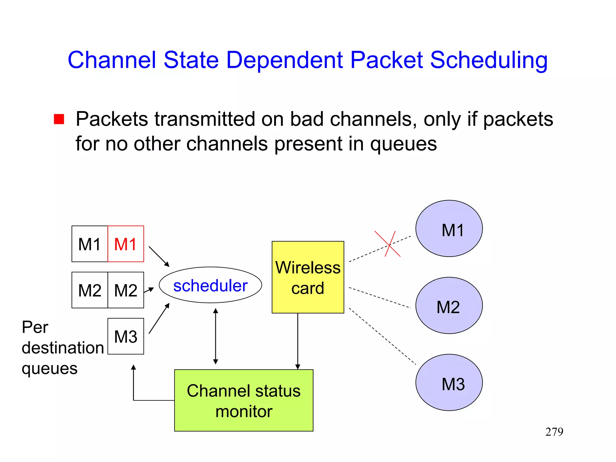
![277
Channel State Dependent Packet Scheduling
[Bhagwat96]
Head-of-the Line blocking can occur with FIFO (first-
in-first-out) scheduling, if sender attempts to
retransmit packets on a channel in a bad state
M1 M2 M3
M2 M1
Wireless
card
M1
M2
M3](https://image.slidesharecdn.com/tcp-wireless-tutorial-220913150100-d90cc118/75/tcp-wireless-tutorial-ppt-277-2048.jpg)

![281
Automatic TCP Buffer Tuning [Semke98]
Using too small buffers can yield poor performance
Using too large buffers can limit number of open
connections
Automatic mechanisms to choose buffer size
dynamically would be useful](https://image.slidesharecdn.com/tcp-wireless-tutorial-220913150100-d90cc118/75/tcp-wireless-tutorial-ppt-281-2048.jpg)


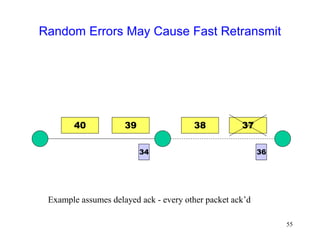
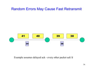
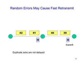
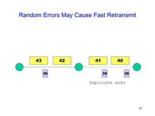
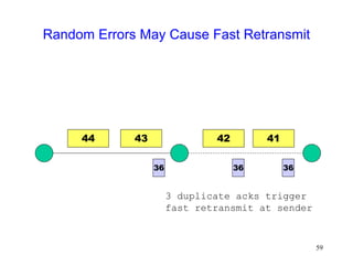
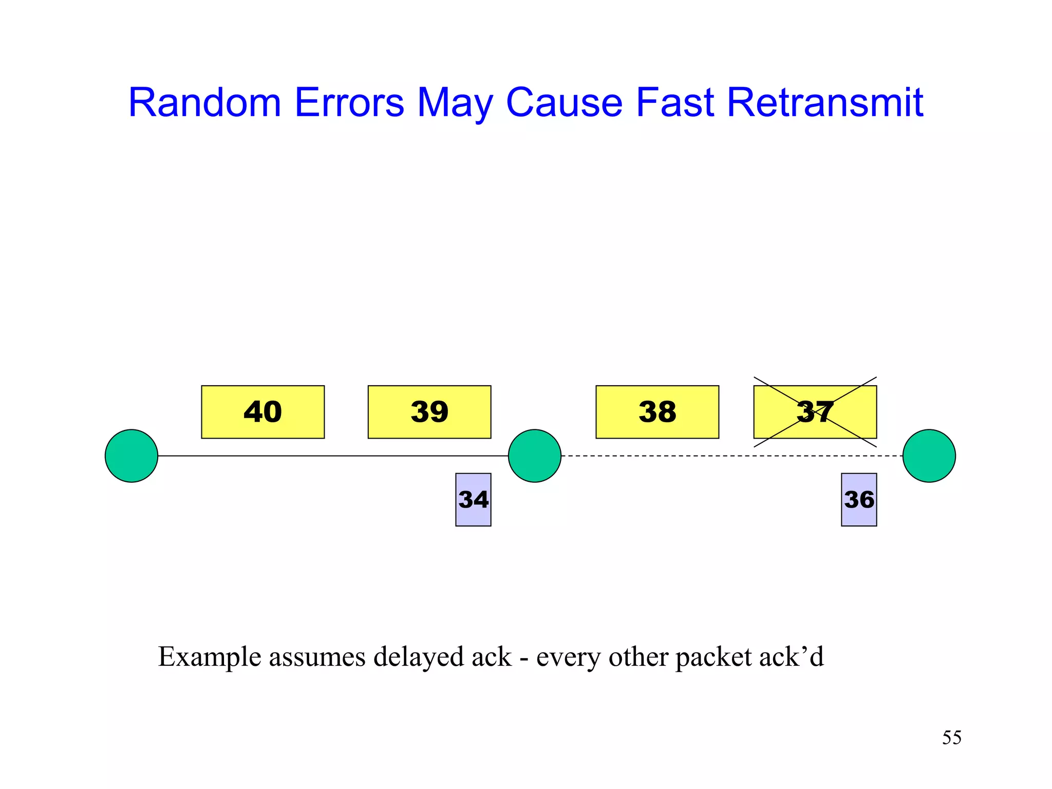
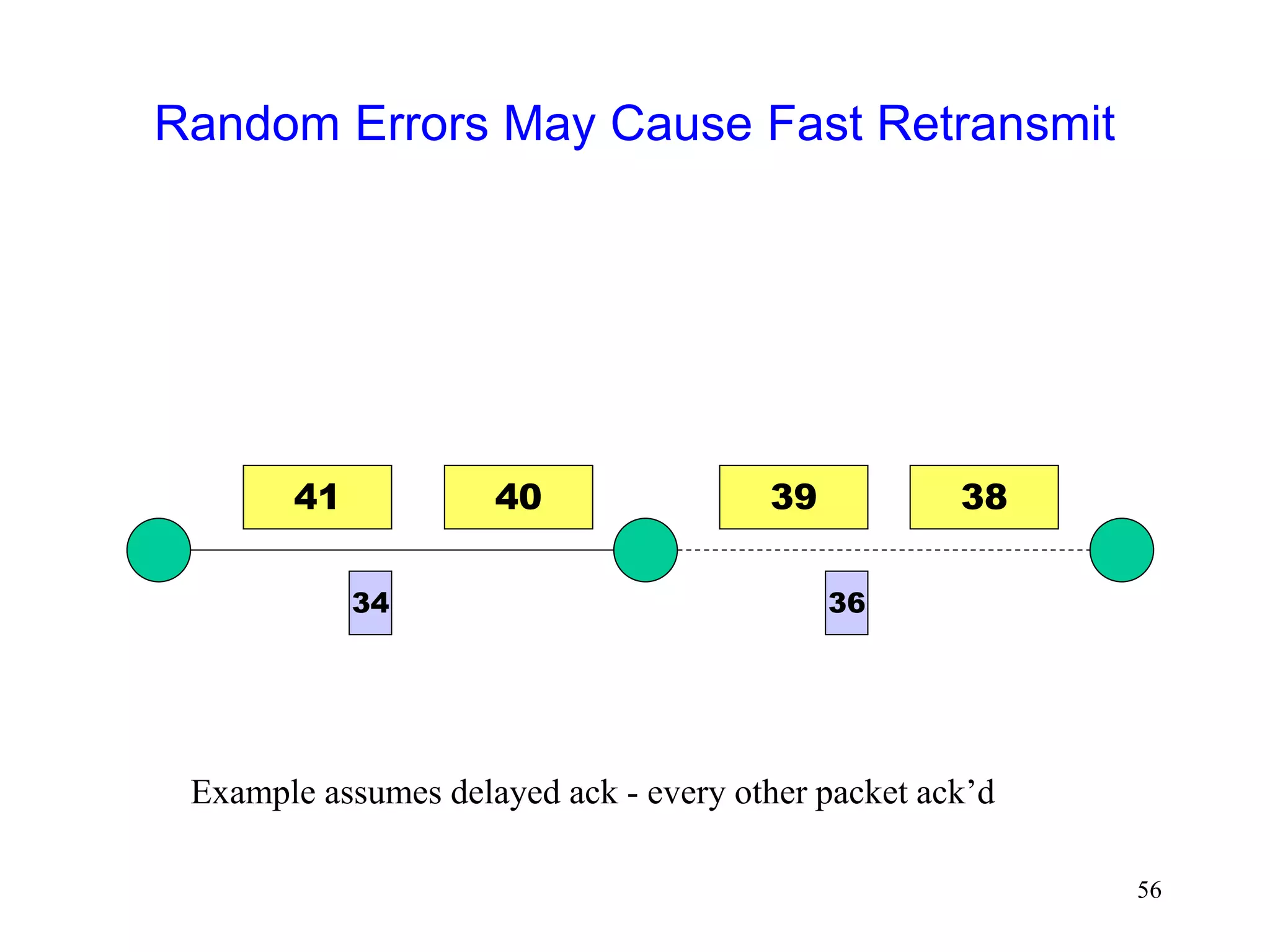
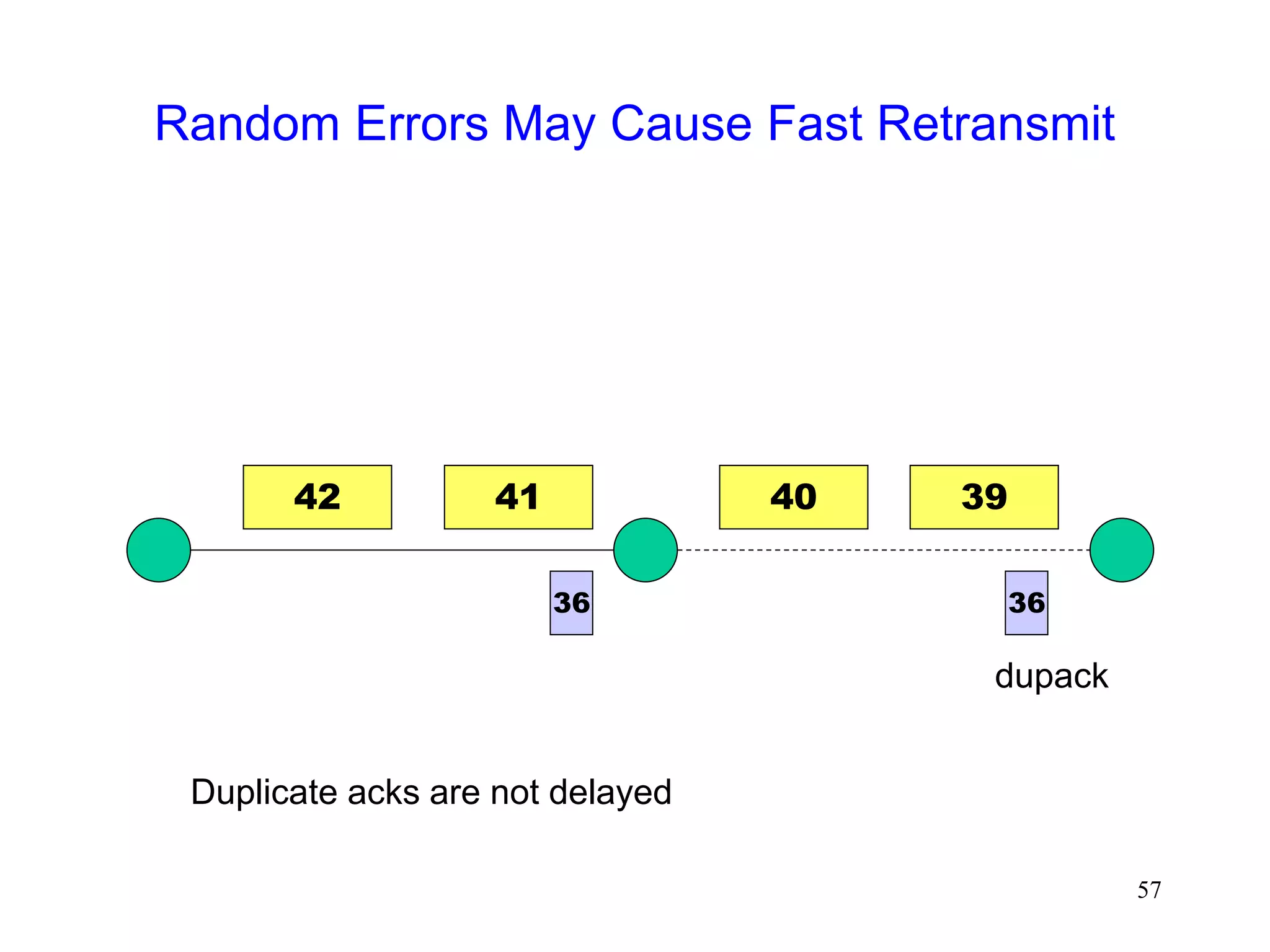
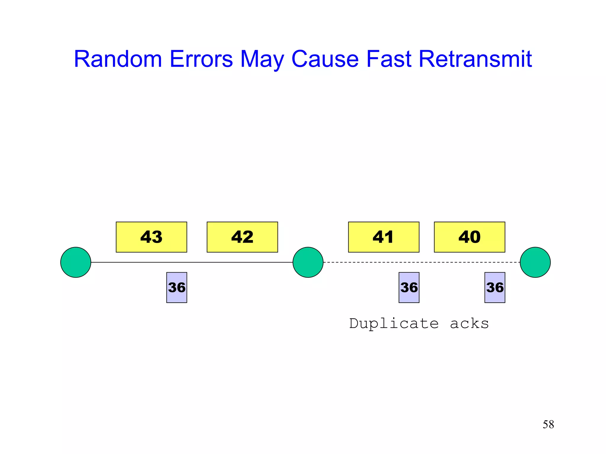
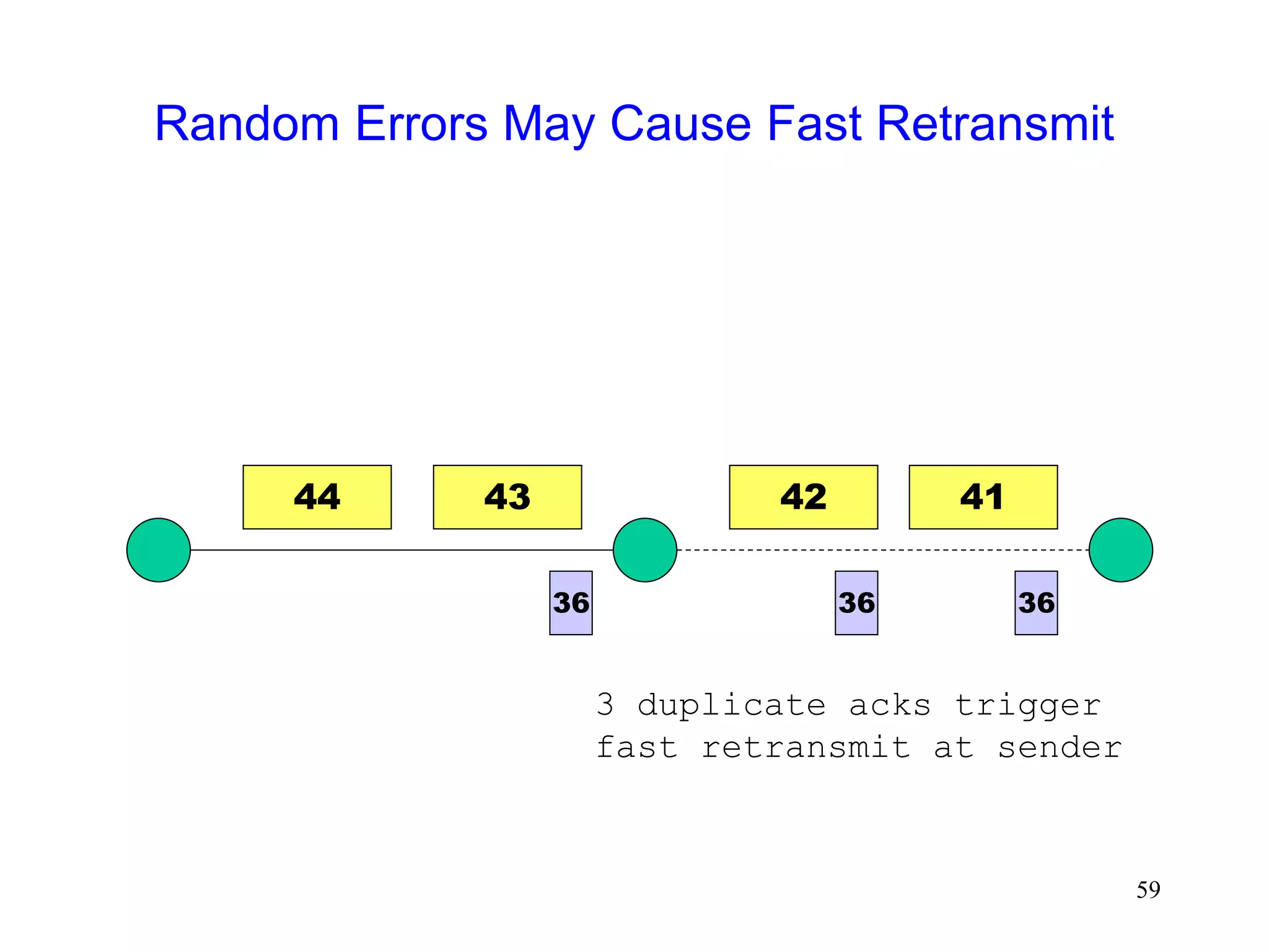
The document discusses TCP performance over wireless networks. It outlines that random transmission errors in wireless networks can cause TCP to trigger its fast retransmit mechanism. This occurs when errors cause duplicate acknowledgements to be generated, which TCP interprets as an indication of packet loss even if the errors are random in nature. The document provides examples of how random errors can generate enough duplicate ACKs to trigger fast retransmit unintentionally.


