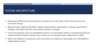
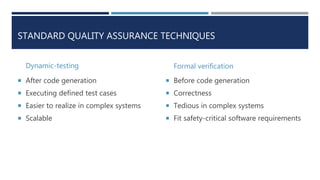
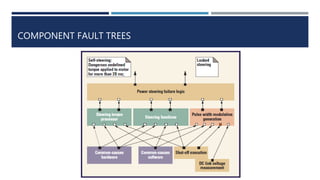
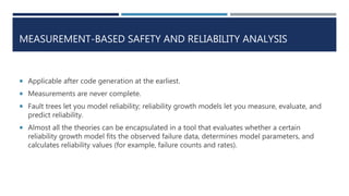
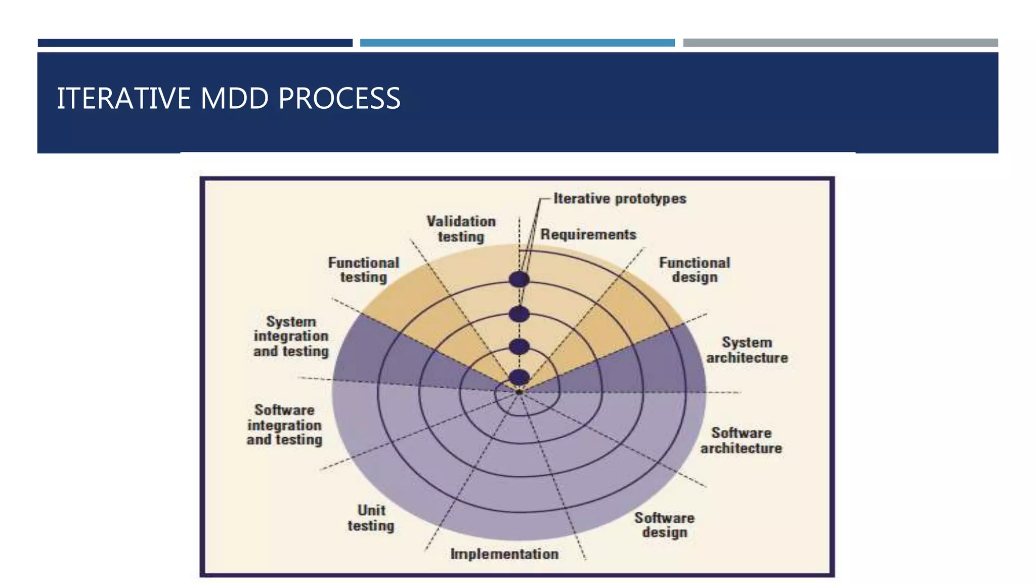
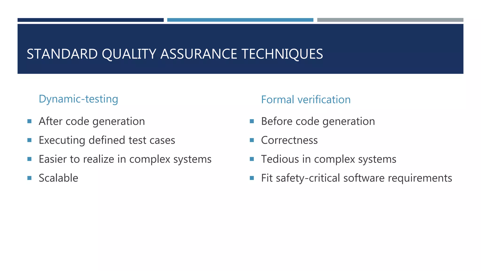
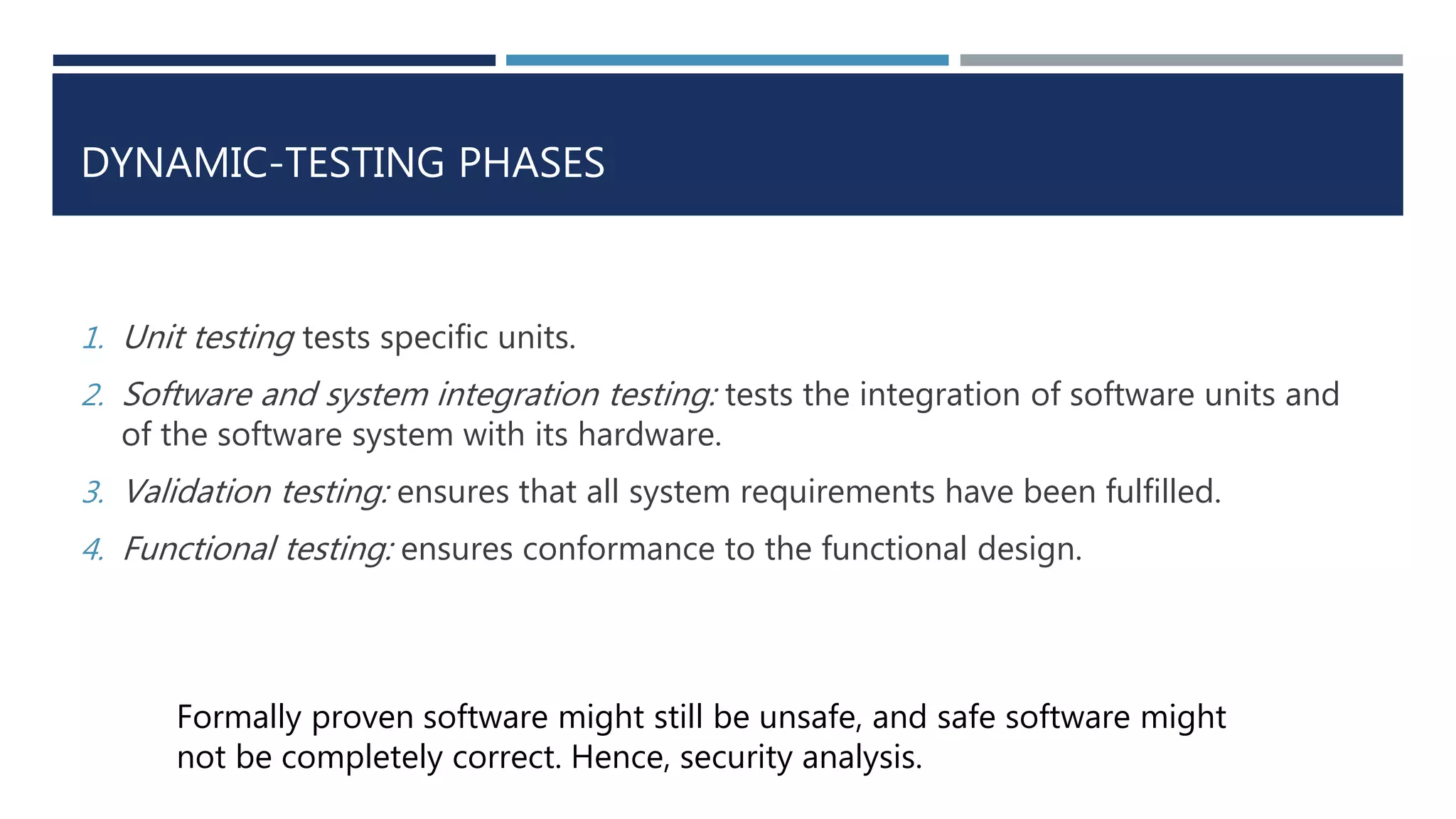
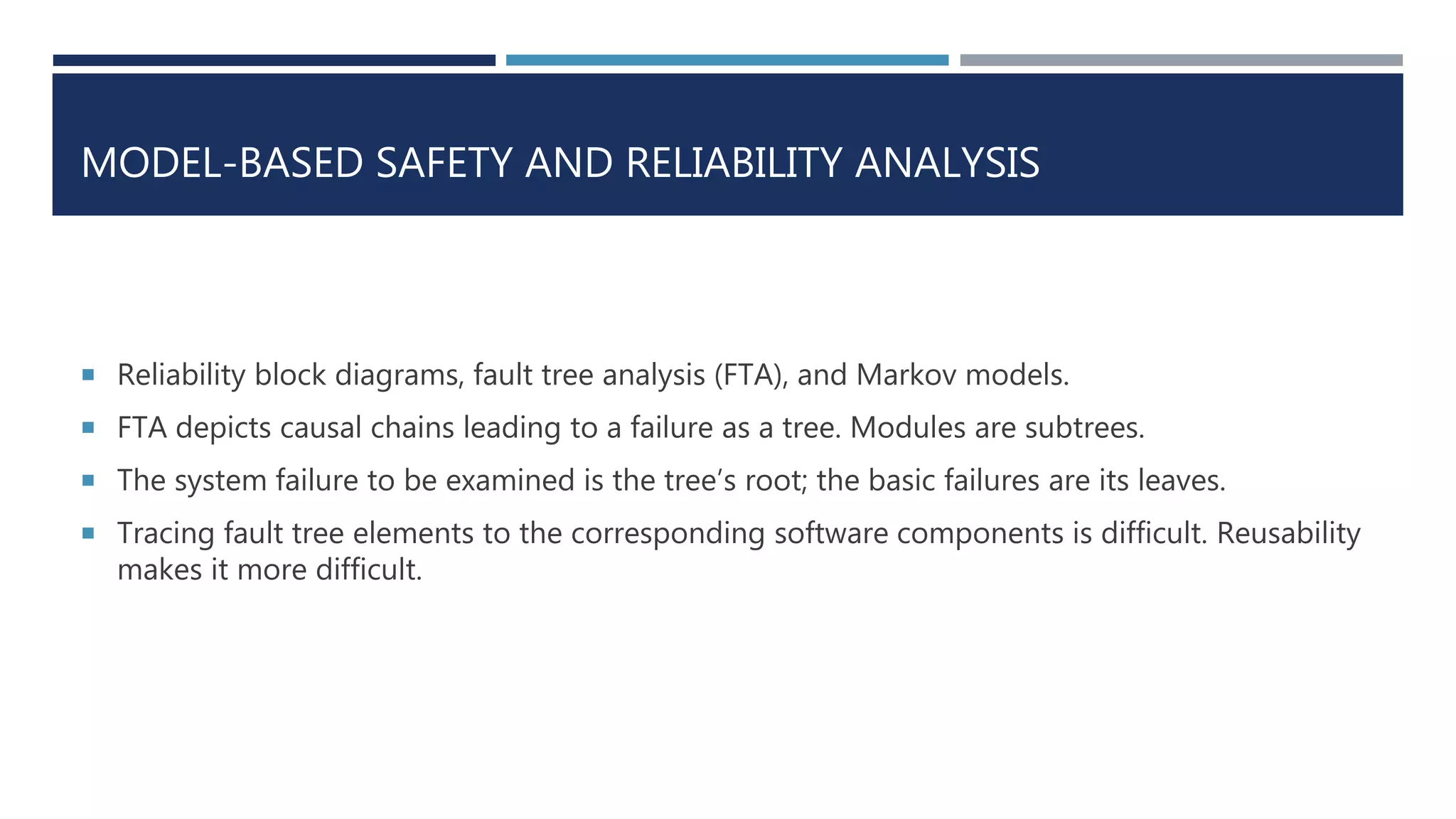
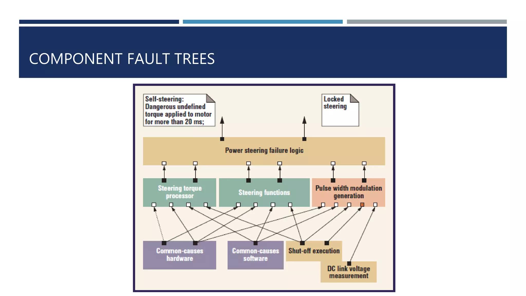
KEMBAR78
Trends in Embedded Software Engineering | PPTX
TRENDS IN EMBEDDED SOFTWARE ENGINEERING
CS 420- Embedded Systems (Spring 2017)
Aditya Kamble
Reference:
Liggesmeyer, Peter, and Mario Trapp. "Trends in embedded software engineering." IEEE software 26.3
(2009).
ABSTRACT
 Development
 IT-like programming
 Model-driven engineering
 Domain-specific development
 Quality Assurance (Safety-Related systems)
 Static and formal verification techniques
 Dynamic Testing
 Safety analysis
 Model-Based Safety and Reliability Analysis
 Measurement-Based Safety and Reliability Analysis
IT SYSTEMS DEVELOPMENT
 Standardized platforms providing the basic infrastructure for service-oriented architectures,
distributed systems, error recovery, and reliability.
 Virtualisation techniques: Scalability and Live migration and hot-spare hardware: Reliability
 Not compatible with Embedded systems domain.
INCOMPATIBILITY REASONS
 Resource requirements(cost, energy, size, or weight constraints) demand the efficient use of
available hardware resources. So, heavyweight abstraction layers, platforms, and virtualization
techniques that require many resources for mapping high-level platforms to concrete
hardware devices aren’t feasible.
 Embedded systems are diverse(mobiles to train-control systems): almost impossible for single
specialized platform.
 Extreme environmental conditions: heat, humidity and radiation.
 Extrafunctional requirements: software safety, reliability, and timeliness.
 Extensive domain knowledge
MODEL DRIVEN DEVELOPMENT(MDD)
 Instead of directly coding software using programming languages, developers model
software systems using intuitive, more expressive, graphical notations
 A higher level of abstraction than native programming languages.
 Model-driven architecture is the primary driver for MDD.
 MDA defines generic concepts of models and model transformations.
 Controlled by a development process (eg. Iterative MDD)
ITERATIVE MDD PROCESS
SYSTEM ARCHITECTURE
 Developers define the actual software architecture on the basis of the requirements and
functional design.
 Requirements-engineering tools support requirements specification, manage requirement
changes, and help track test case results and test coverage.
 Functional designs cover an embedded system’s functionalities without considering technical
implementation details. Instead, they consist of a computationally independent model.
 Refine the different components and connections to obtain an executable, but still platform-
independent system.
DOMAIN-SPECIFIC DEVELOPMENT
 Why?
 MDD is based on general purpose languages and code generators for different application
domains. Contradicts the optimization of the language and code generators to a given
application context, and to the hardware platform used.
 Domain-specific modeling uses domain-specific concepts. Provides more-intuitive modeling
languages and integrates more software developer know-how and application-specific
optimizations into the code generators.
EXAMPLE- CONDITION-MONITORING SYSTEMS FOR
HYDRAULIC SYSTEMS
FEATURES
 Provides a formal model with a clear syntax and semantics, enabling code generation based
on the specifications.
 Efficient code because modeling elements have rich semantics and the family of possible
target platforms is known.
 All the software development expertise required from this specification is encapsulated in the
code generator, libraries, and the platform software, which might include an operating system
or a microkernel.
QUALITY ASSURANCE
SAFETY-RELATED SYSTEMS
STANDARD QUALITY ASSURANCE TECHNIQUES
Dynamic-testing
 After code generation
 Executing defined test cases
 Easier to realize in complex systems
 Scalable
Formal verification
 Before code generation
 Correctness
 Tedious in complex systems
 Fit safety-critical software requirements
DYNAMIC-TESTING PHASES
1. Unit testing tests specific units.
2. Software and system integration testing: tests the integration of software units and
of the software system with its hardware.
3. Validation testing: ensures that all system requirements have been fulfilled.
4. Functional testing: ensures conformance to the functional design.
Formally proven software might still be unsafe, and safe software might
not be completely correct. Hence, security analysis.
SAFETY AND RELIABILITY ANALYSIS
MODEL-BASED AND MEASUREMENT-BASED
MODEL-BASED SAFETY AND RELIABILITY ANALYSIS
 Reliability block diagrams, fault tree analysis (FTA), and Markov models.
 FTA depicts causal chains leading to a failure as a tree. Modules are subtrees.
 The system failure to be examined is the tree’s root; the basic failures are its leaves.
 Tracing fault tree elements to the corresponding software components is difficult. Reusability
makes it more difficult.
COMPONENT FAULT TREES
MEASUREMENT-BASED SAFETY AND RELIABILITY ANALYSIS
 Applicable after code generation at the earliest.
 Measurements are never complete.
 Fault trees let you model reliability; reliability growth models let you measure, evaluate, and
predict reliability.
 Almost all the theories can be encapsulated in a tool that evaluates whether a certain
reliability growth model fits the observed failure data, determines model parameters, and
calculates reliability values (for example, failure counts and rates).
CONCLUSION
 Different approaches for the development and quality assurance of embedded
software systems exist in the industry.
 Techniques for systematically developing embedded software can hardly keep up
with the ever-growing demand for new functionalities and technologies.
 For safety-critical systems, new functionalities are useless if you can’t ensure their
quality and safety.
 The rapid progress of systematic software engineering technologies will be a key
factor in the successful future development of even more-complex embedded
systems.
THANK YOU!

Trends in Embedded Software Engineering

  • 1.
    TRENDS IN EMBEDDEDSOFTWARE ENGINEERING CS 420- Embedded Systems (Spring 2017) Aditya Kamble Reference: Liggesmeyer, Peter, and Mario Trapp. "Trends in embedded software engineering." IEEE software 26.3 (2009).
  • 2.
    ABSTRACT  Development  IT-likeprogramming  Model-driven engineering  Domain-specific development  Quality Assurance (Safety-Related systems)  Static and formal verification techniques  Dynamic Testing  Safety analysis  Model-Based Safety and Reliability Analysis  Measurement-Based Safety and Reliability Analysis
  • 3.
    IT SYSTEMS DEVELOPMENT Standardized platforms providing the basic infrastructure for service-oriented architectures, distributed systems, error recovery, and reliability.  Virtualisation techniques: Scalability and Live migration and hot-spare hardware: Reliability  Not compatible with Embedded systems domain.
  • 4.
    INCOMPATIBILITY REASONS  Resourcerequirements(cost, energy, size, or weight constraints) demand the efficient use of available hardware resources. So, heavyweight abstraction layers, platforms, and virtualization techniques that require many resources for mapping high-level platforms to concrete hardware devices aren’t feasible.  Embedded systems are diverse(mobiles to train-control systems): almost impossible for single specialized platform.  Extreme environmental conditions: heat, humidity and radiation.  Extrafunctional requirements: software safety, reliability, and timeliness.  Extensive domain knowledge
  • 5.
    MODEL DRIVEN DEVELOPMENT(MDD) Instead of directly coding software using programming languages, developers model software systems using intuitive, more expressive, graphical notations  A higher level of abstraction than native programming languages.  Model-driven architecture is the primary driver for MDD.  MDA defines generic concepts of models and model transformations.  Controlled by a development process (eg. Iterative MDD)
  • 6.
  • 7.
    SYSTEM ARCHITECTURE  Developersdefine the actual software architecture on the basis of the requirements and functional design.  Requirements-engineering tools support requirements specification, manage requirement changes, and help track test case results and test coverage.  Functional designs cover an embedded system’s functionalities without considering technical implementation details. Instead, they consist of a computationally independent model.  Refine the different components and connections to obtain an executable, but still platform- independent system.
  • 8.
    DOMAIN-SPECIFIC DEVELOPMENT  Why? MDD is based on general purpose languages and code generators for different application domains. Contradicts the optimization of the language and code generators to a given application context, and to the hardware platform used.  Domain-specific modeling uses domain-specific concepts. Provides more-intuitive modeling languages and integrates more software developer know-how and application-specific optimizations into the code generators.
  • 9.
  • 10.
    FEATURES  Provides aformal model with a clear syntax and semantics, enabling code generation based on the specifications.  Efficient code because modeling elements have rich semantics and the family of possible target platforms is known.  All the software development expertise required from this specification is encapsulated in the code generator, libraries, and the platform software, which might include an operating system or a microkernel.
  • 11.
  • 12.
    STANDARD QUALITY ASSURANCETECHNIQUES Dynamic-testing  After code generation  Executing defined test cases  Easier to realize in complex systems  Scalable Formal verification  Before code generation  Correctness  Tedious in complex systems  Fit safety-critical software requirements
  • 13.
    DYNAMIC-TESTING PHASES 1. Unittesting tests specific units. 2. Software and system integration testing: tests the integration of software units and of the software system with its hardware. 3. Validation testing: ensures that all system requirements have been fulfilled. 4. Functional testing: ensures conformance to the functional design. Formally proven software might still be unsafe, and safe software might not be completely correct. Hence, security analysis.
  • 14.
    SAFETY AND RELIABILITYANALYSIS MODEL-BASED AND MEASUREMENT-BASED
  • 15.
    MODEL-BASED SAFETY ANDRELIABILITY ANALYSIS  Reliability block diagrams, fault tree analysis (FTA), and Markov models.  FTA depicts causal chains leading to a failure as a tree. Modules are subtrees.  The system failure to be examined is the tree’s root; the basic failures are its leaves.  Tracing fault tree elements to the corresponding software components is difficult. Reusability makes it more difficult.
  • 16.
  • 17.
    MEASUREMENT-BASED SAFETY ANDRELIABILITY ANALYSIS  Applicable after code generation at the earliest.  Measurements are never complete.  Fault trees let you model reliability; reliability growth models let you measure, evaluate, and predict reliability.  Almost all the theories can be encapsulated in a tool that evaluates whether a certain reliability growth model fits the observed failure data, determines model parameters, and calculates reliability values (for example, failure counts and rates).
  • 18.
    CONCLUSION  Different approachesfor the development and quality assurance of embedded software systems exist in the industry.  Techniques for systematically developing embedded software can hardly keep up with the ever-growing demand for new functionalities and technologies.  For safety-critical systems, new functionalities are useless if you can’t ensure their quality and safety.  The rapid progress of systematic software engineering technologies will be a key factor in the successful future development of even more-complex embedded systems.
  • 19.

Editor's Notes

  • #3 With embedded software’s increasing complexity and quality demands, software engineering’s role is becoming more important and the paper exactly addresses this. So the flow of ppt goes like this we first focus on the developments aspects and then on quality assurance.
  • #4 It all starts with the IT development. Involves standard platforms providing basic infrastructure for SOA, distributed systems, deals with errors and hence, reliability. But even with these provisions this approach is not quite compatible for es domain.
  • #5 Coming to the reasons for this, first of all, as we saw in the previous slide it involves heavyweight abstraction layers, platforms and virtualisation techniques. All these cannot be feasible considering several constraints on cost, energy, weight and size. Moreover, embedded systems are diverse like from mobiles to trains so a single platform is difficult even to imagine. And they are rarely a standalone product. Thirdly, these systems have to deal with extreme environmental conditions like heat, wind, rain. The need to create specialized hardware and software platforms is a key difference between IT systems and embedded systems.For example, IT system users are accustomed to waiting for the system to react, but a car won’t stop moving to wait for its control system to return a calculation.Extrafunctional requirements contribute to these difficulties. And finally an extensive domain knowledge is required; developing a vehicle stability control system is impossible if you don’t understand the physics of vehicle dynamics.
  • #6 MDD is one of the promising approaches that has emerged over the last decade. In this, Instead of directly coding, developers model software systems using various graphical notations. This provides an abstraction which helps to get an idea of what is going on and should be done. MDA is primary in MDD and it defines the generic concepts, models and transformations. It is controlled by a development process one of the example is iterative mdd.
  • #7 As we can see, this encompass all phases of the development life cycle and lets developers produce partial implementations after each iteration, with the most critical aspects implemented first. Some other dev processes are the UML-based Ropes (Rapid Object-Oriented Process for Embedded Systems), which is based on the spiral process model; different approaches based on a V-Model
  • #8 developers have to formulate actual s/w archi on basis of requirements and functional design there are some tools like UML to create and manage requirements and changes. Functional design are computationally independant model and don't consider technical implementation details. This is a manual process because creativity is required. a lack of tool support and integration makes it impossible to seamlessly cover the complete development life cycle using model-driven-engineering paradigms.
  • #9 Following the shift from assembly language to high-level programming languages, and from programming to model-based design, comes the shift from MDD to domain-specific development. It takes a step away from general purpose development followed by MDD which basically used to contradict optimization idea between hardware and software platform compatibility. Whereas dsd provides more intuitive modeling and integrates the know-how, optimizations into the code generators.
  • #10 One of the example is condition-monitoring systems for hydraulic systems shown here. In this view of the model, developers simply define which sensors they use to monitor the hydraulics system and connect them to the respective input ports of the monitoring hardware. The complete code to configure the sensors and to retrieve and to interpret the sensor readings is then generated completely automatically.
  • #11 So, to emphasize the features of dsd first of all it provides a formal model with syntax and semantics enabling code generation. The generated code is efficient because the model has rich semantics and target platform is known. Moreover, the expertise like libraries, sometimes OS too is encapsulated in code generator itself. But we do require engineers too for creating the domain-specific language and tool chain & domain experts then use them to build an embedded software system. So, domain-specific development won’t completely replace MDD; rather, hybrid solutions are more likely.
  • #12 Now, coming to the 2nd aspect that is quality asssurance. The focus of this paper is mainly on safety related systems. Aim is to ensure the quality of functional and extrafunctional properties of these systems.
  • #13 The standard 2 techniques involved are dynamic-testing and formal verification. These are few differences between them. the first is performed after code generation whereas the 2nd before. dt involves executing defined testcases and validating whereas in fv correctness is more focused. It is obvious that the 1st will be more easy to realize in case of complex system because you test on the go and in these systems it is really difficult to formalize everything right at start. Finally, the first is scalable but formal techniques are quite safety-critical and abide strictly to the requirements.
  • #14 The dynamic testing phases are unit testing, s/w & integration testing, validation testing and functional testing. as mentioned before, applying formal techniques to a complete, complex software system isn’t that straightforward. Moreover, formally proven software might still be unsafe, and safe software might not be completely correct. Correctness clearly supports safety, but it doesn’t substitute for safety analysis.
  • #15 This brings us to the safety and reliability analysis. ensuring the quality of a system’s functional and extrafunctional properties is crucial particularly for safety-related systems.
  • #16 The 1st one is model based analysis. Consists of reliability block diagrams, FTA, markov models. The paper has emphasized on FTA. It depicts causal chains leading to failure as a tree. The modules are subtrees. The ultimate system failure is examined at tree's root whereas basic failures such as component failures are its leaves. One main concern is that tracing fault tree elements to corresponding s/w components is difficult and reusability further makes it difficult. Hence, the move on to component FTs.
  • #17 They extend conventional fault trees using real components that are connected via ports They simplify fault tree analyses of complex software systems. The fault tree in this figure describes two top events of an active power steering system—namely, locked steering and self-steering. The active power steering system is decomposed to different components such as the power steering torque processor. The component fault tree follows the structure of the system and thus simplifies the mapping between functional model and safety model, enables division of labor, and improves the reusability of fault tree components.
  • #18 2nd is measurement based analysis. It comes into picture after code genration. As we know measurements are never complete. 1st the FTs let you model reliablity, then it lets you measure, evaluate and predict reliability. Reliability is basically based on values like failure rates and counts.
  • #19 So, to conclude, the paper has discussed different existing approaches for development and quality assurance. We've noticed that techniques for systematic development can hardly keep up with the ever growing demand for new technology and functionality. But without quality and safety, new functionalities are useless. Hence, the rapid progress will be the key factor in successful future development of more complex embedded systems.