UNIT-3
Design Using UML
Building Blocks of UML
Defining things
relationships and diagrams
Common Mechanism in UML
Class and Object Diagrams.
2.
Design Using UML
UML
Unified modelling language : It is a system that allows a software designer to
graphically layout and model a software application. It gives designers a way
to literally draw a map of how a piece of software will be constructed and
function
UML describes the real-time systems, it is very important to make a
conceptual model and then proceed gradually. The conceptual model of
UML can be mastered by learning the following three major elements.
• UML building blocks
• Rules to connect the building blocks
• Common mechanisms of UML
3.
Characteristics of UML
TheUML has the following features:
• It is a generalized modelling language.
• It is distinct from other programming languages like C++, Python, etc.
• It is interrelated to object-oriented analysis and design.
• It is used to visualize the workflow of the system.
• It is a pictorial language, used to generate powerful modelling artifacts
4.
Design Using UML
Building Blocks of UML
The building blocks of UML can be defined as −
• Things
• Relationships
• Diagrams
Things: Anything that is a real world entity or object is termed as things.
Things are the most important building blocks of UML. Four types of Things .
They are
Structural Things
Behavioral Things
Grouping Things
Annotational Things
5.
Structural Things
BuildingBlocks of UML
Structural Things
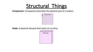
Structural things are the Nouns that depicts the static behavior of a model, is termed as
structural things.
Structural things display the physical and conceptual components.
Structural things include
• Class
• Object
• Interface
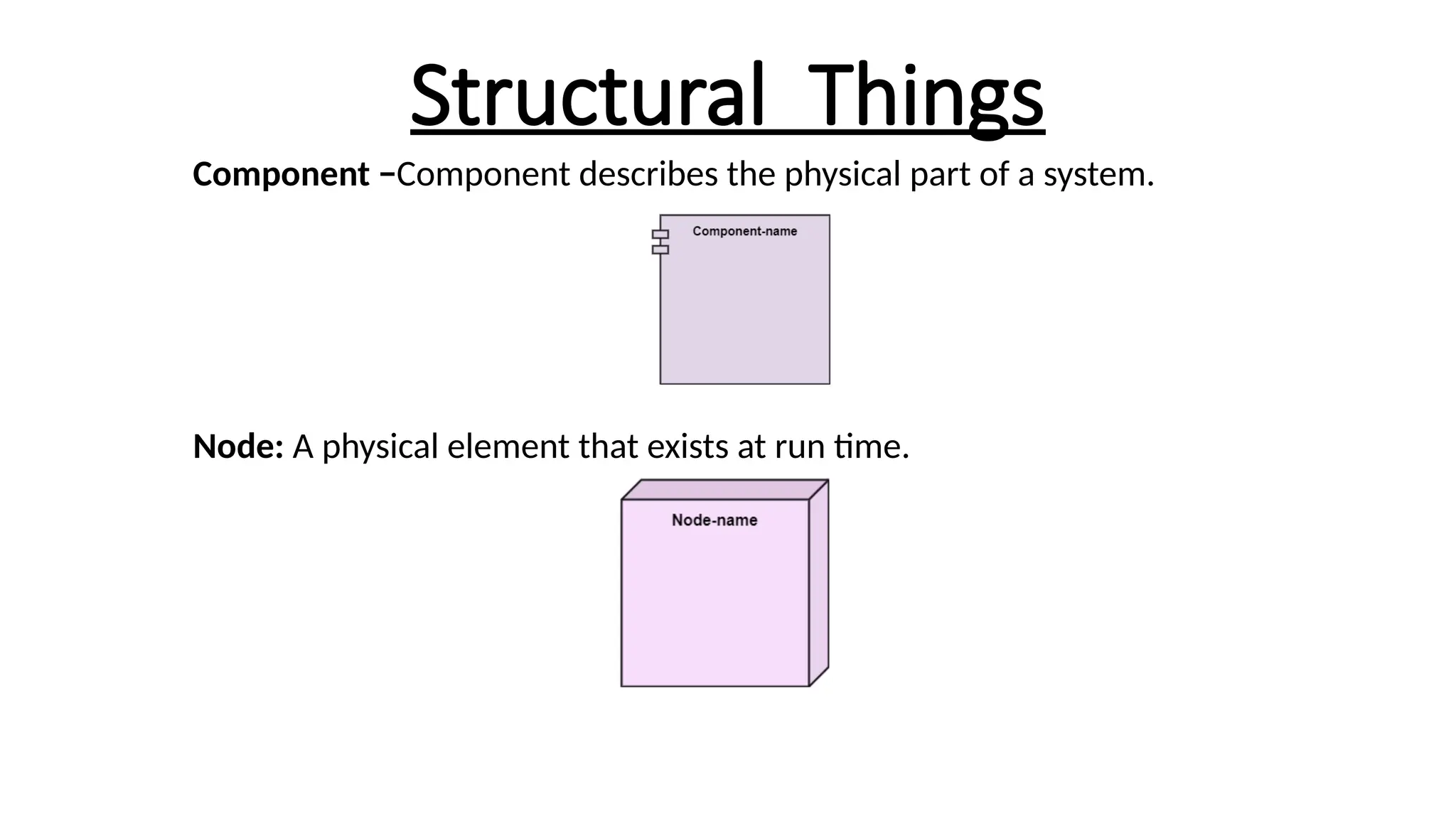
• Node
• Collaboration
• Component
• Use case.
6.
Structural Things
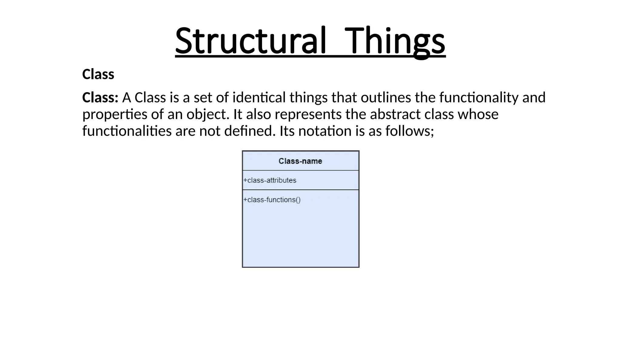
Class
Class: AClass is a set of identical things that outlines the functionality and
properties of an object. It also represents the abstract class whose
functionalities are not defined. Its notation is as follows;
7.
Structural Things
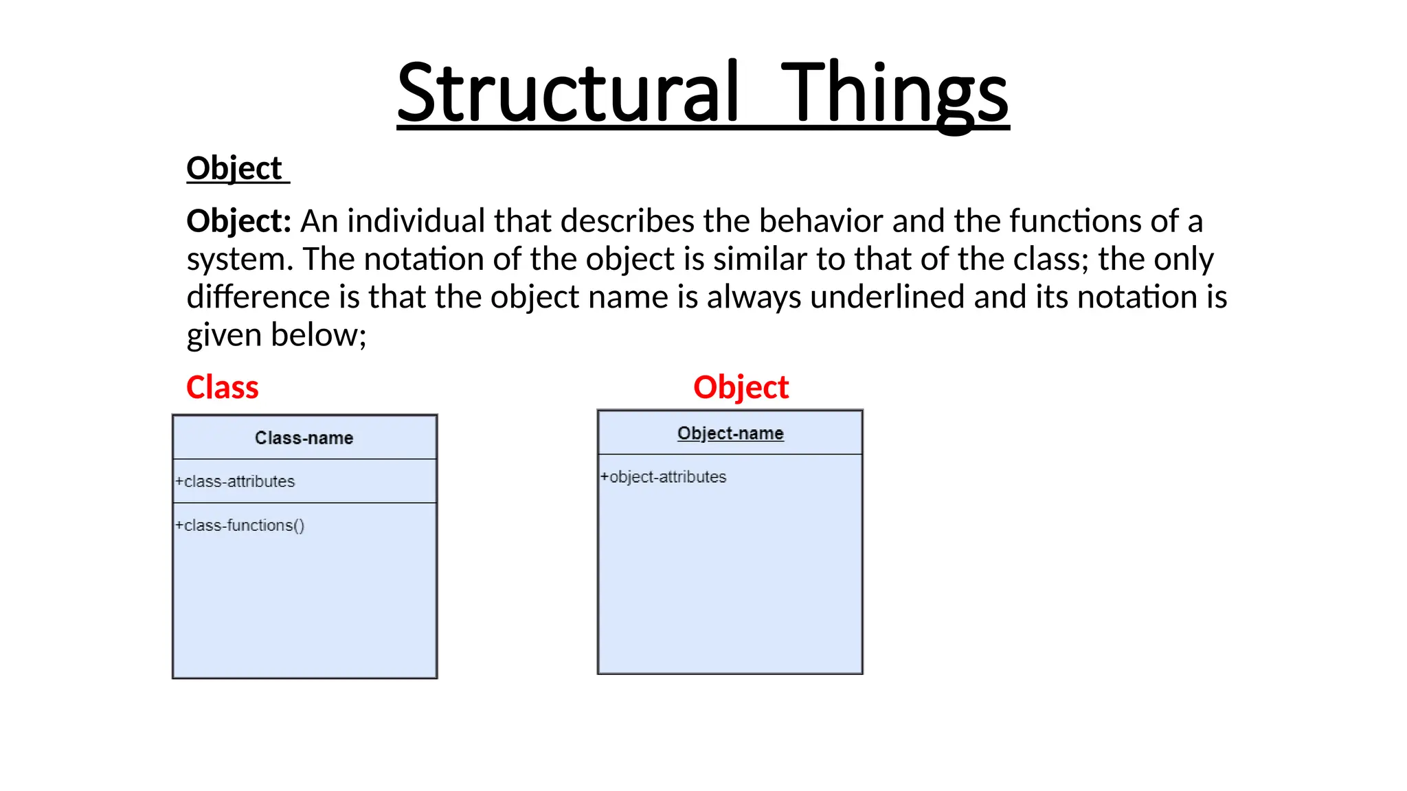
Object
Object: Anindividual that describes the behavior and the functions of a
system. The notation of the object is similar to that of the class; the only
difference is that the object name is always underlined and its notation is
given below;
Class Object
8.
Structural Things
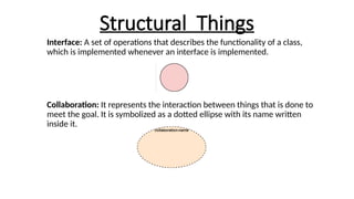
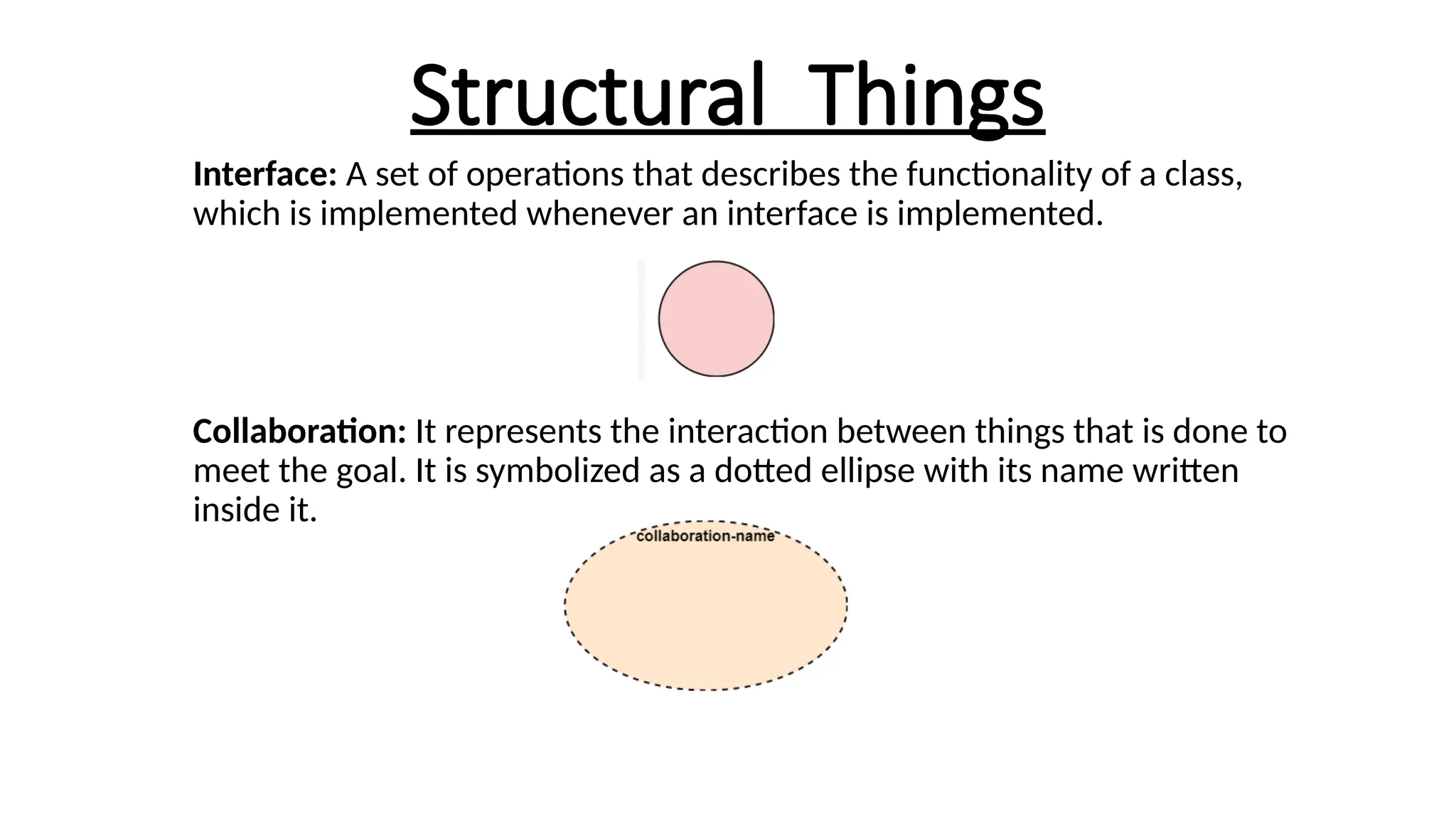
Interface: Aset of operations that describes the functionality of a class,
which is implemented whenever an interface is implemented.
Collaboration: It represents the interaction between things that is done to
meet the goal. It is symbolized as a dotted ellipse with its name written
inside it.
9.
Structural Things
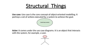
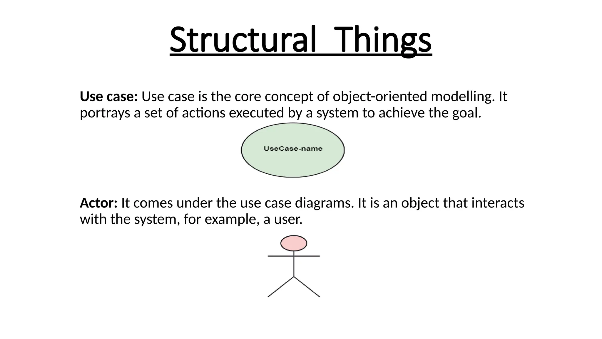
Use case:Use case is the core concept of object-oriented modelling. It
portrays a set of actions executed by a system to achieve the goal.
Actor: It comes under the use case diagrams. It is an object that interacts
with the system, for example, a user.
Behavioural Things
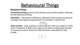
Behavioural Things
Abehavioural thing consists of the dynamic parts of UML models. Following
are the behavioural things.
Interaction − Interaction is defined as a behaviour that consists of a group of
messages exchanged among elements to accomplish a specific task.
State machine − State machine is useful when the state of an object in its life
cycle is important. It defines the sequence of states an object goes through
in response to events. Events are external factors responsible for state
change.
12.
Grouping Things
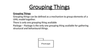
Grouping Things
Groupingthings can be defined as a mechanism to group elements of a
UML model together.
There is only one grouping thing available
Package − Package is the only one grouping thing available for gathering
structural and behavioural things.
13.
Annotational Things
Annotational Things
Annotationalthings can be defined as a mechanism to
capture remarks, descriptions, and comments of UML model
elements.
Note - It is the only one Annotational thing available. A note
is used to render comments, constraints, etc. of an UML
element.
14.
Relationships
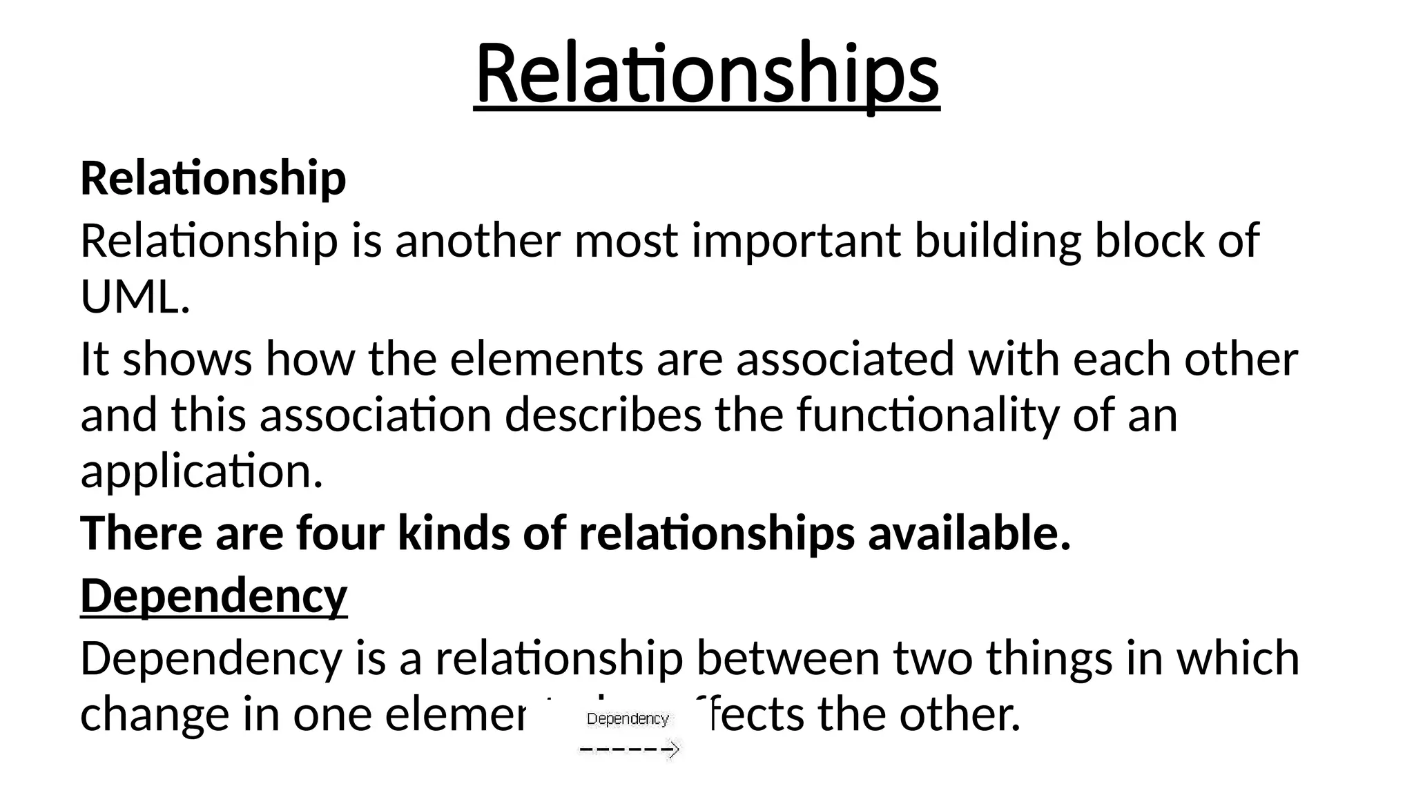
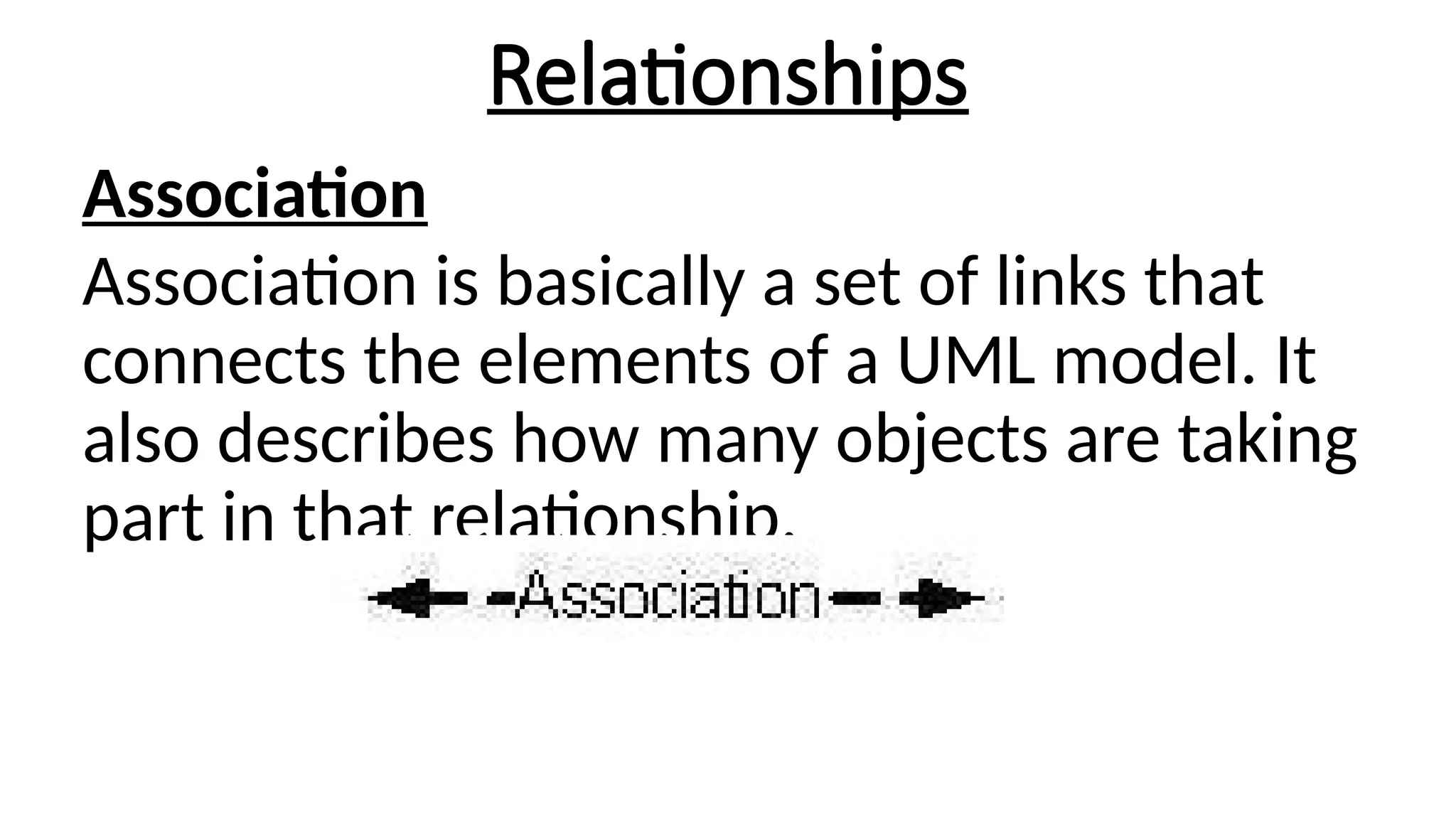
Relationship
Relationship is anothermost important building block of
UML.
It shows how the elements are associated with each other
and this association describes the functionality of an
application.
There are four kinds of relationships available.
Dependency
Dependency is a relationship between two things in which
change in one element also affects the other.
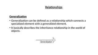
Relationships
Generalization
• Generalization canbe defined as a relationship which connects a
specialized element with a generalized element.
• It basically describes the inheritance relationship in the world of
objects.
17.
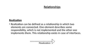
Relationships
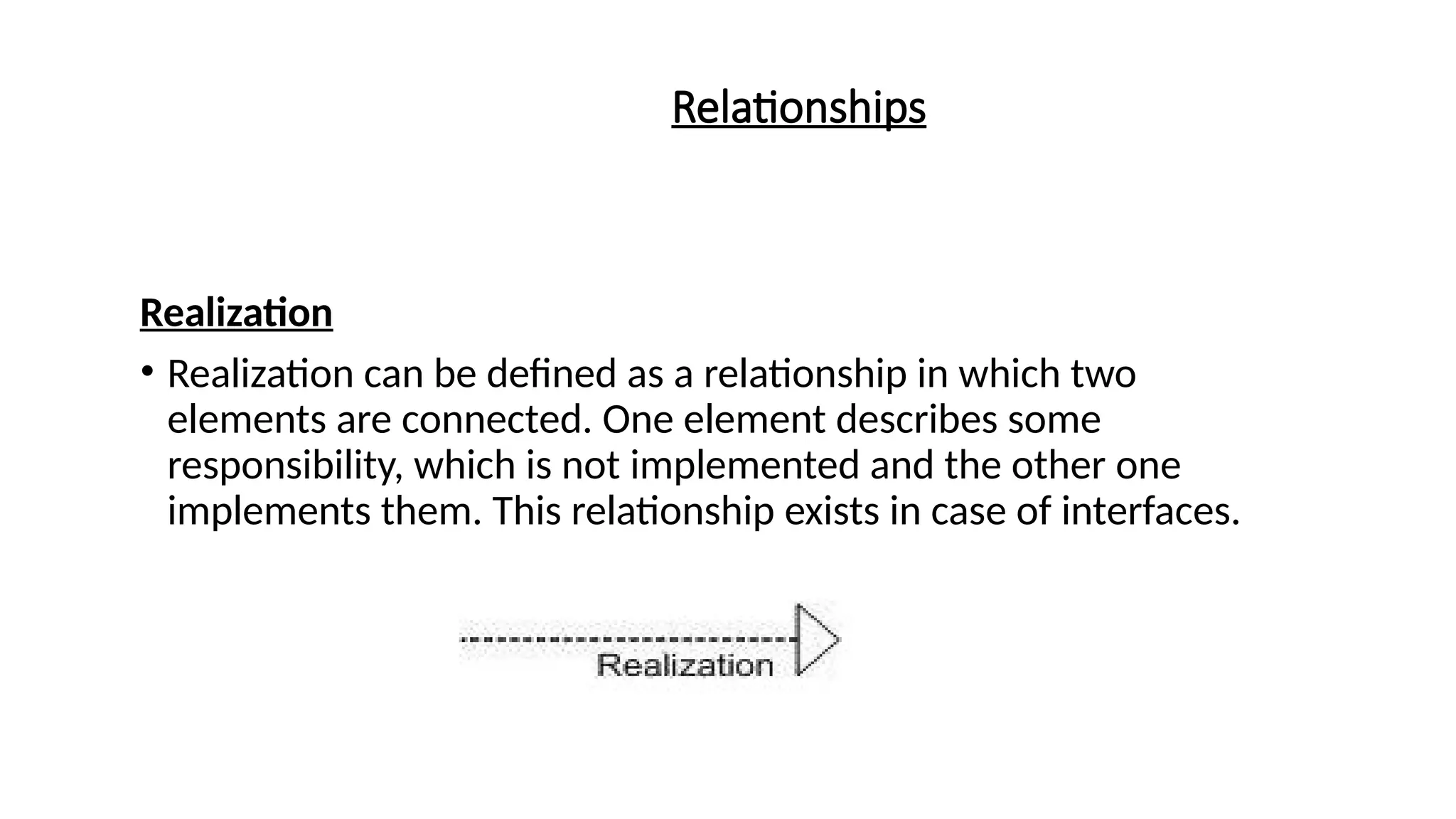
Realization
• Realization canbe defined as a relationship in which two
elements are connected. One element describes some
responsibility, which is not implemented and the other one
implements them. This relationship exists in case of interfaces.
18.
UML Diagrams
• UMLdiagrams are the ultimate output of the entire discussion.
• All the elements, relationships are used to make a complete UML
diagram and the diagram represents a system.
• The visual effect of the UML diagram is the most important part of
the entire process.
• All the other elements are used to make it complete.
• UML includes the nine diagrams, the details are described in the
subsequent chapters.
19.
UML Diagrams
The Ninediagrams of UML are
Class diagram
Object diagram
Use case diagram
Sequence diagram
Collaboration diagram
Activity diagram
State chart diagram
Deployment diagram
Component diagram
20.
Class Diagram
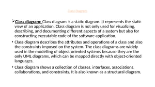
Class diagram:Class diagram is a static diagram. It represents the static
view of an application. Class diagram is not only used for visualizing,
describing, and documenting different aspects of a system but also for
constructing executable code of the software application.
• Class diagram describes the attributes and operations of a class and also
the constraints imposed on the system. The class diagrams are widely
used in the modelling of object oriented systems because they are the
only UML diagrams, which can be mapped directly with object-oriented
languages.
• Class diagram shows a collection of classes, interfaces, associations,
collaborations, and constraints. It is also known as a structural diagram.
21.
Class Diagram
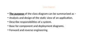
• Thepurpose of the class diagram can be summarized as −
• Analysis and design of the static view of an application.
• Describe responsibilities of a system.
• Base for component and deployment diagrams.
• Forward and reverse engineering
22.
Class Diagram
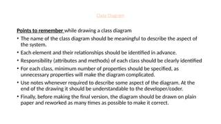
Points toremember while drawing a class diagram
• The name of the class diagram should be meaningful to describe the aspect of
the system.
• Each element and their relationships should be identified in advance.
• Responsibility (attributes and methods) of each class should be clearly identified
• For each class, minimum number of properties should be specified, as
unnecessary properties will make the diagram complicated.
• Use notes whenever required to describe some aspect of the diagram. At the
end of the drawing it should be understandable to the developer/coder.
• Finally, before making the final version, the diagram should be drawn on plain
paper and reworked as many times as possible to make it correct.
23.
Class Diagram
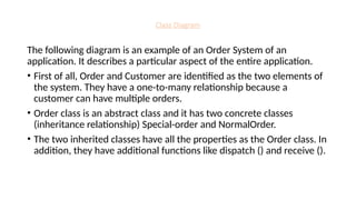
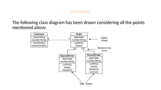
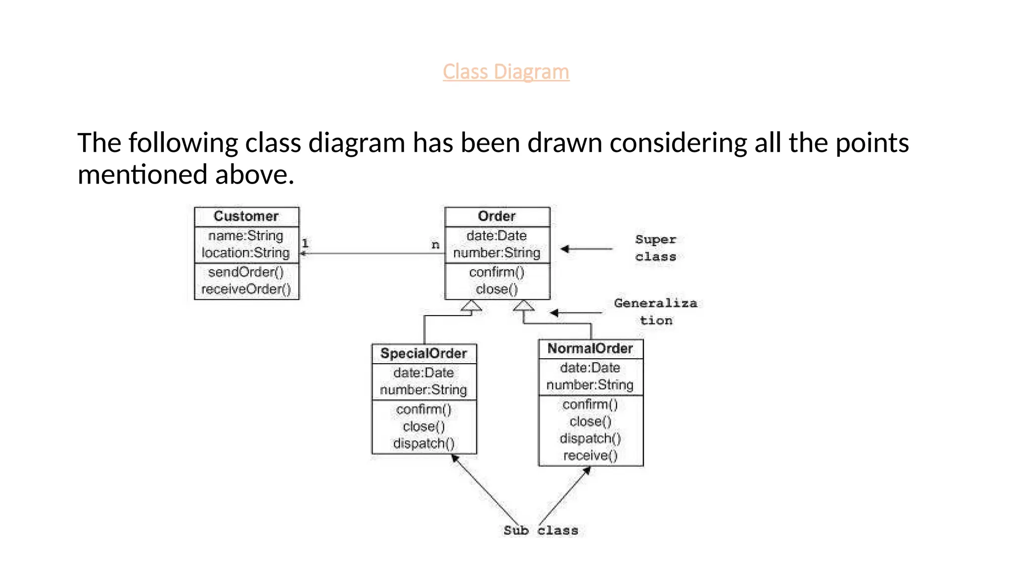
The followingdiagram is an example of an Order System of an
application. It describes a particular aspect of the entire application.
• First of all, Order and Customer are identified as the two elements of
the system. They have a one-to-many relationship because a
customer can have multiple orders.
• Order class is an abstract class and it has two concrete classes
(inheritance relationship) Special-order and NormalOrder.
• The two inherited classes have all the properties as the Order class. In
addition, they have additional functions like dispatch () and receive ().
Class Diagram
Class diagramsare used for −
• Describing the static view of the system.
• Showing the collaboration among the elements of the static view.
• Describing the functionalities performed by the system.
• Construction of software applications using object oriented
languages.
26.
Object Diagrams
Object diagram:
•Object diagrams are derived from class diagrams so object diagrams
are dependent upon class diagrams.
• Object diagrams represent an instance of a class diagram. The basic
concepts are similar for class diagrams and object diagrams. Object
diagrams also represent the static view of a system.
• Object diagrams are used to render (Provide) a set of objects and
their relationships as an instance.
27.
Object Diagrams
Purpose ofObject Diagrams:
• The purposes of object diagrams are similar to class diagrams.
• The class diagram represents an abstract model consisting of classes and their
relationships.
• An object diagram represents an instance at a particular moment, which is
concrete in nature.
• Forward and reverse engineering.
• Object relationships of a system
• Static view of an interaction.
• Understand object behaviour and their relationship from practical perspective
28.
Object Diagrams
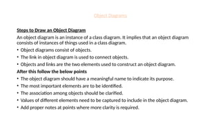
Steps toDraw an Object Diagram
An object diagram is an instance of a class diagram. It implies that an object diagram
consists of instances of things used in a class diagram.
• Object diagrams consist of objects.
• The link in object diagram is used to connect objects.
• Objects and links are the two elements used to construct an object diagram.
After this follow the below points
• The object diagram should have a meaningful name to indicate its purpose.
• The most important elements are to be identified.
• The association among objects should be clarified.
• Values of different elements need to be captured to include in the object diagram.
• Add proper notes at points where more clarity is required.
29.
Object Diagrams
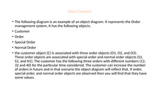
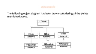
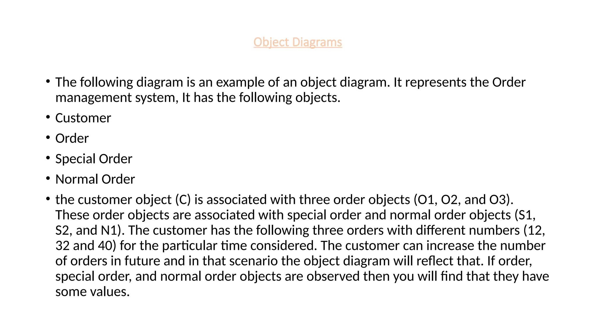
• Thefollowing diagram is an example of an object diagram. It represents the Order
management system, It has the following objects.
• Customer
• Order
• Special Order
• Normal Order
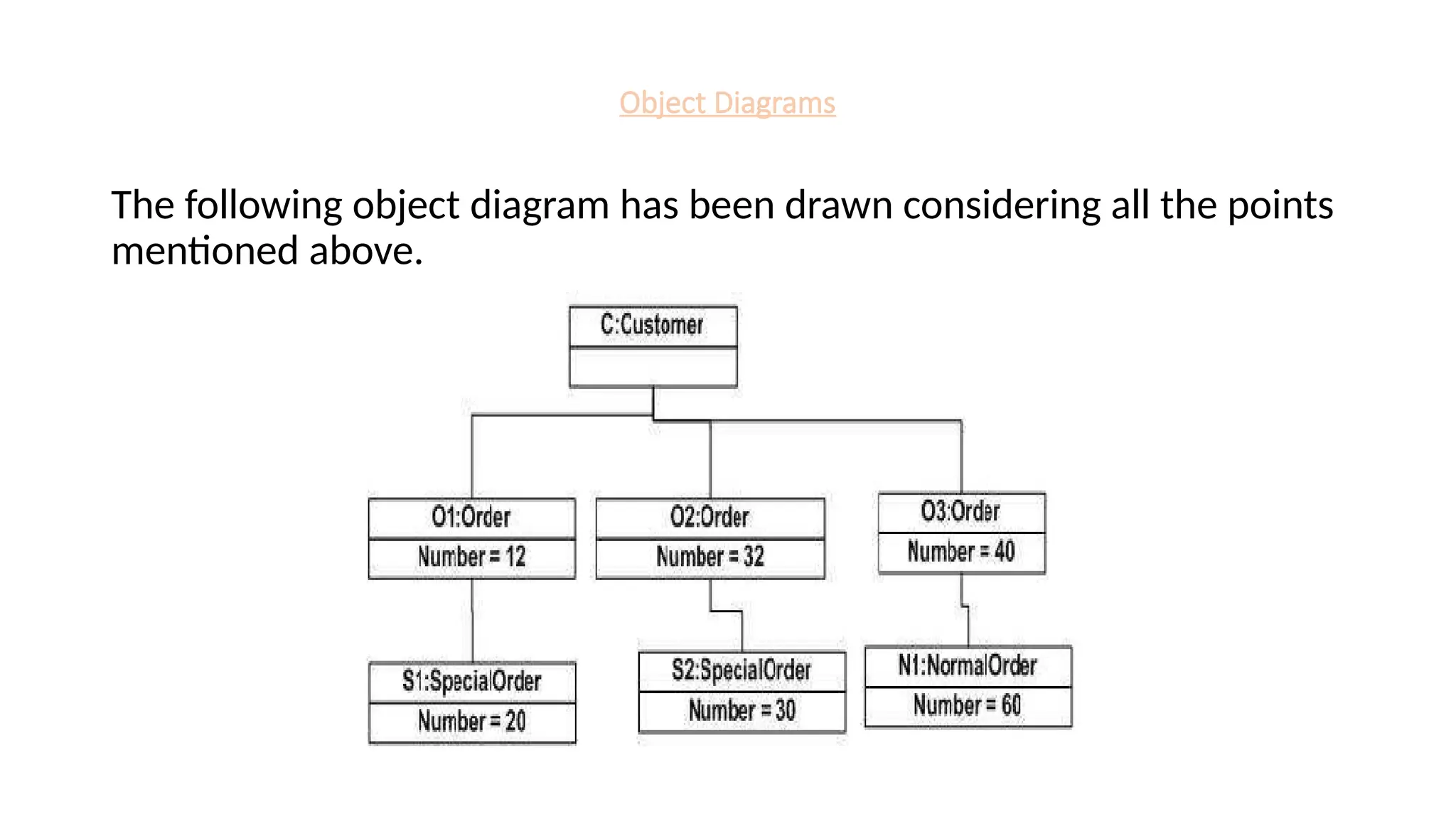
• the customer object (C) is associated with three order objects (O1, O2, and O3).
These order objects are associated with special order and normal order objects (S1,
S2, and N1). The customer has the following three orders with different numbers (12,
32 and 40) for the particular time considered. The customer can increase the number
of orders in future and in that scenario the object diagram will reflect that. If order,
special order, and normal order objects are observed then you will find that they have
some values.
30.
Object Diagrams
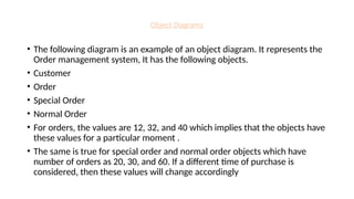
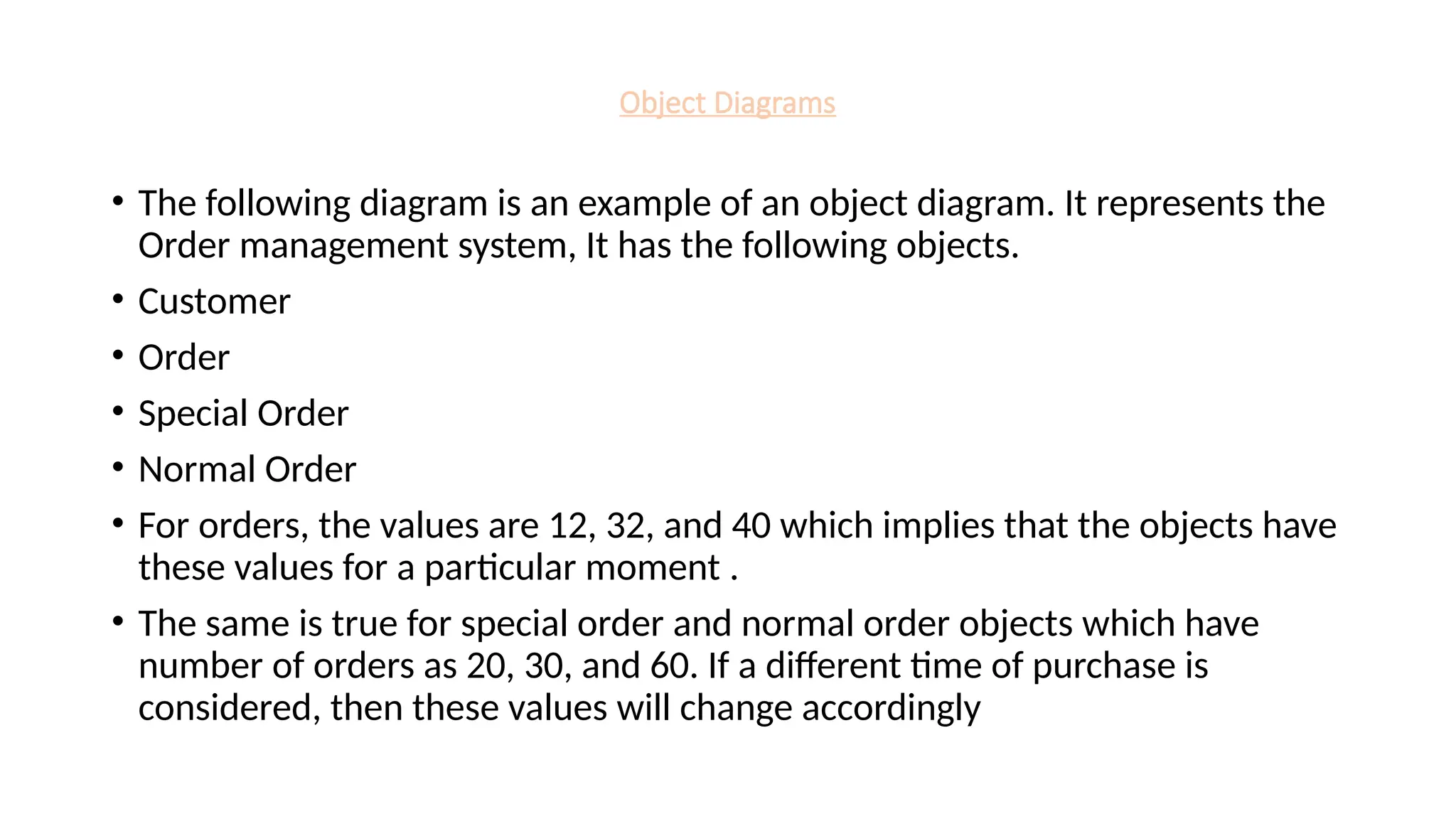
• Thefollowing diagram is an example of an object diagram. It represents the
Order management system, It has the following objects.
• Customer
• Order
• Special Order
• Normal Order
• For orders, the values are 12, 32, and 40 which implies that the objects have
these values for a particular moment .
• The same is true for special order and normal order objects which have
number of orders as 20, 30, and 60. If a different time of purchase is
considered, then these values will change accordingly
Object Diagrams
The objectdiagrams are used for −
• Making the prototype of a system.
• Reverse engineering.
• Modelling complex data structures.
• Understanding the system from practical perspective.
33.
Use Case Diagrams
UseCase Diagram:
Use case diagrams are used to capture the dynamic behaviour.
Dynamic behaviour means the behaviour of the system when it is
running/operating.
Use case diagrams consists of actors, use cases and their
relationships. The diagram is used to model the system/subsystem of
an application. A single use case diagram captures a particular
functionality of a system.
34.
Use Case Diagrams
Purposeof Use Case Diagrams
The purpose of use case diagram is to capture the dynamic aspect of
a system.
• Used to gather the requirements of a system.
• Used to get an outside view of a system.
• Identify the external and internal factors influencing the system.
• Show the interaction among the requirements are actors.
• Actors can be a human user, some internal applications, or may be
some external applications.
35.
Use Case Diagrams
Followingare the guidelines to draw an efficient use case diagram
• The name of a use case is very important. The name should be chosen
in such a way so that it can identify the functionalities performed.
• Give a suitable name for actors.
• Show relationships and dependencies clearly in the diagram.
• Do not try to include all types of relationships, as the main purpose of
the diagram is to identify the requirements.
• Use notes whenever required to clarify some important points.
36.
Use Case Diagrams
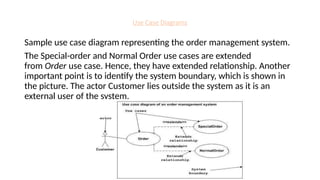
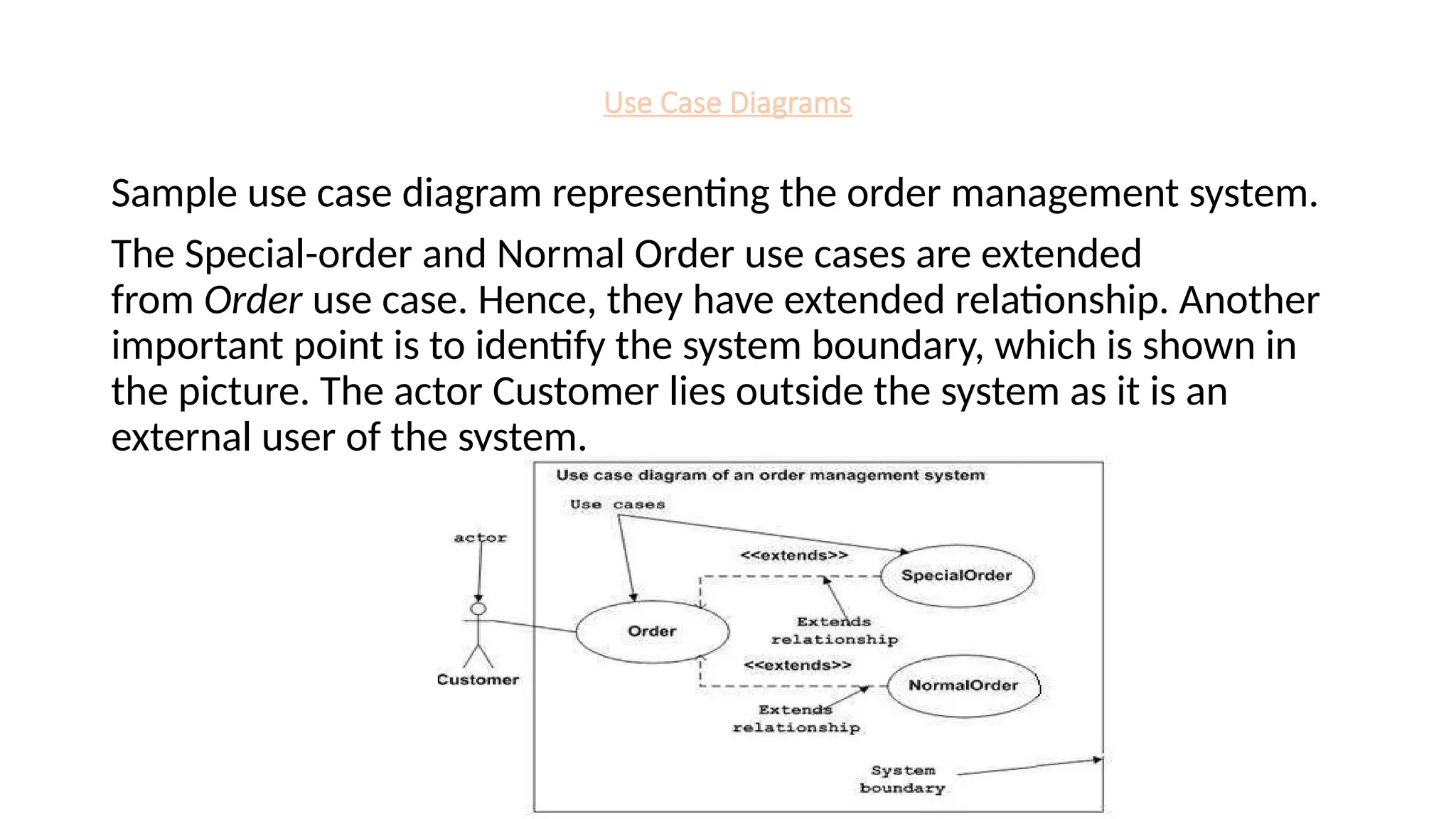
Sampleuse case diagram representing the order management system.
The Special-order and Normal Order use cases are extended
from Order use case. Hence, they have extended relationship. Another
important point is to identify the system boundary, which is shown in
the picture. The actor Customer lies outside the system as it is an
external user of the system.
37.
Sequence and CollaborationDiagrams
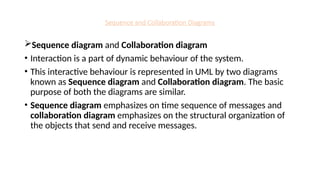
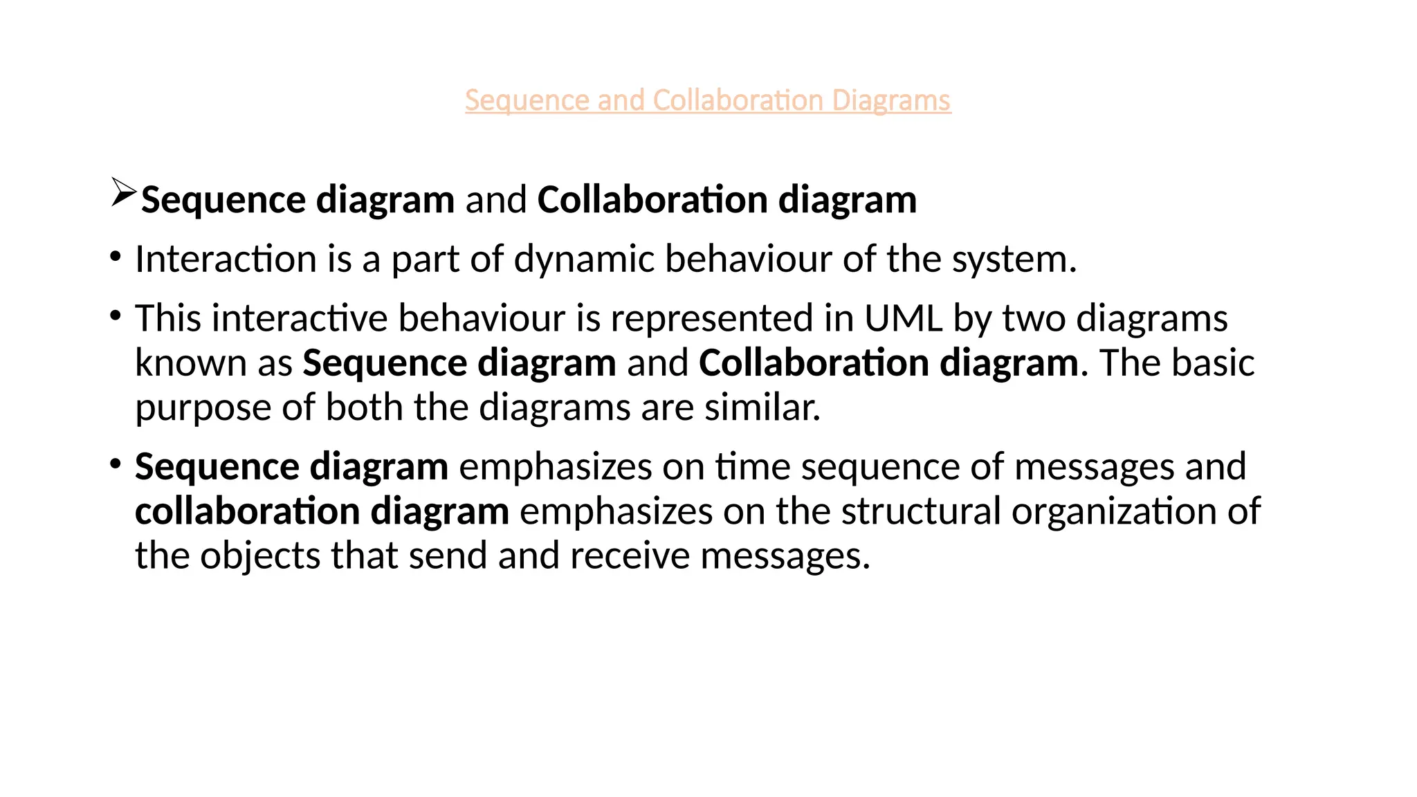
Sequence diagram and Collaboration diagram
• Interaction is a part of dynamic behaviour of the system.
• This interactive behaviour is represented in UML by two diagrams
known as Sequence diagram and Collaboration diagram. The basic
purpose of both the diagrams are similar.
• Sequence diagram emphasizes on time sequence of messages and
collaboration diagram emphasizes on the structural organization of
the objects that send and receive messages.
38.
Sequence and CollaborationDiagrams
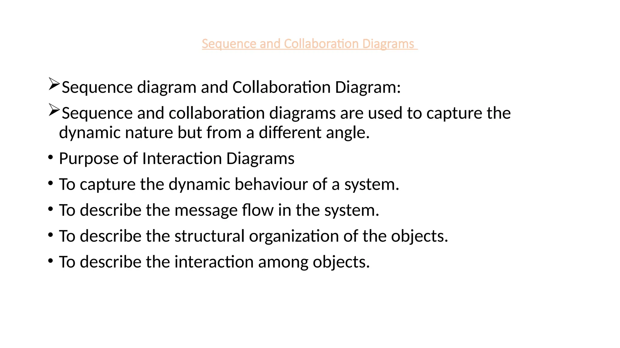
Sequence diagram and Collaboration Diagram:
Sequence and collaboration diagrams are used to capture the
dynamic nature but from a different angle.
• Purpose of Interaction Diagrams
• To capture the dynamic behaviour of a system.
• To describe the message flow in the system.
• To describe the structural organization of the objects.
• To describe the interaction among objects.
39.
Sequence Diagram
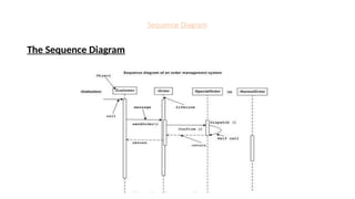
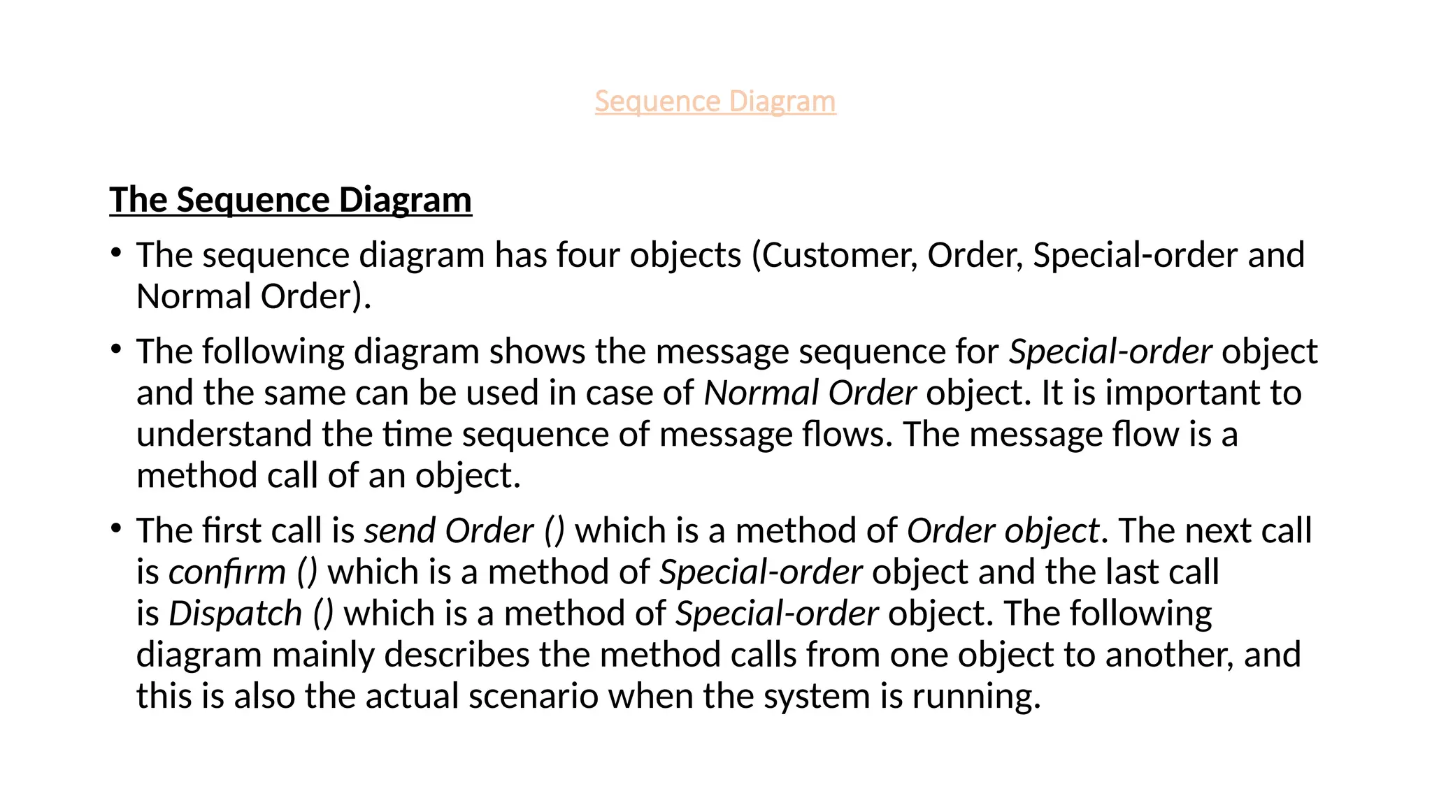
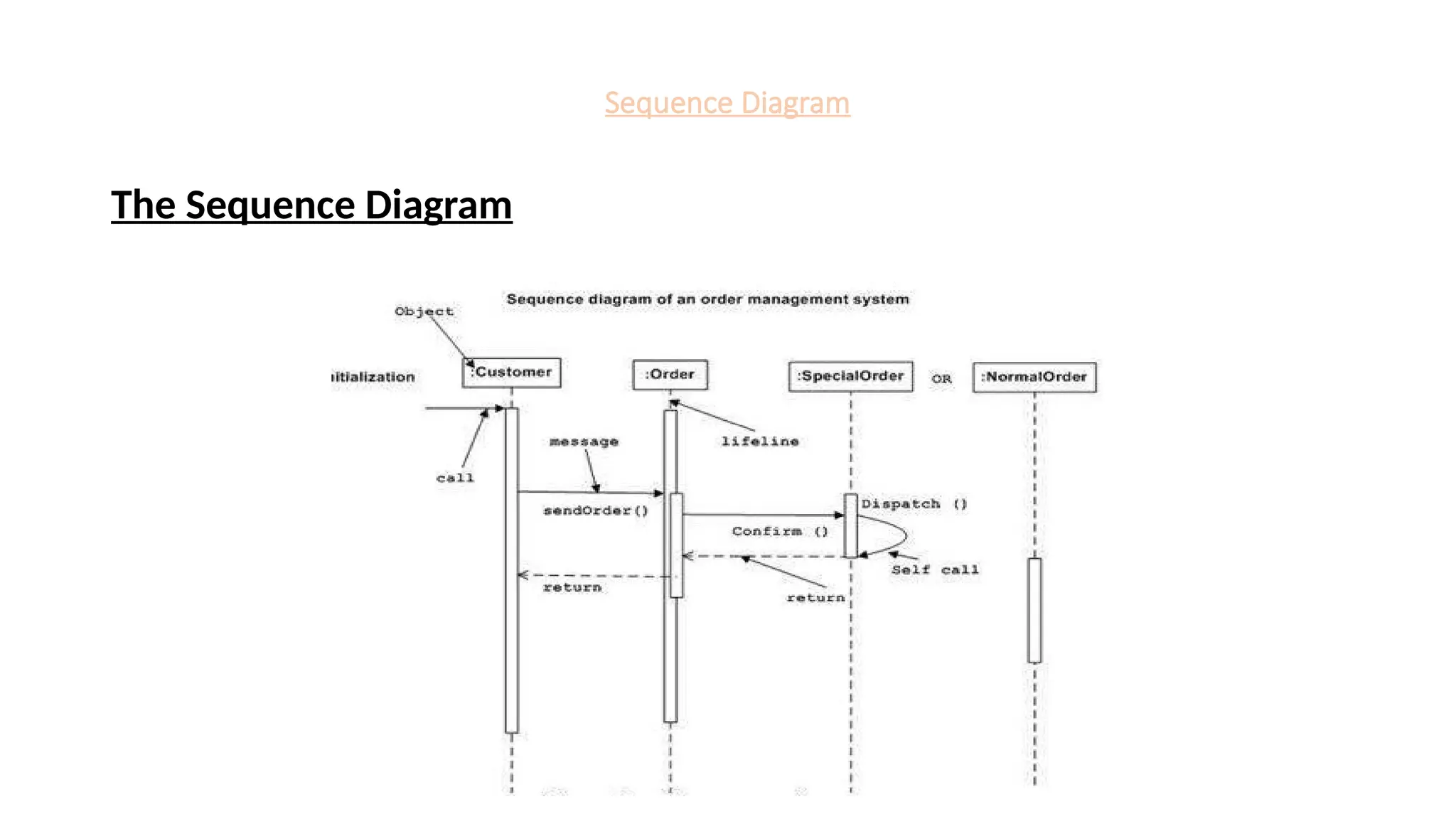
The SequenceDiagram
• The sequence diagram has four objects (Customer, Order, Special-order and
Normal Order).
• The following diagram shows the message sequence for Special-order object
and the same can be used in case of Normal Order object. It is important to
understand the time sequence of message flows. The message flow is a
method call of an object.
• The first call is send Order () which is a method of Order object. The next call
is confirm () which is a method of Special-order object and the last call
is Dispatch () which is a method of Special-order object. The following
diagram mainly describes the method calls from one object to another, and
this is also the actual scenario when the system is running.
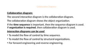
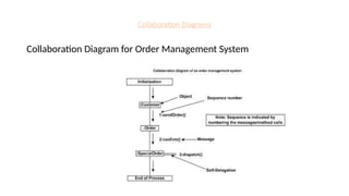
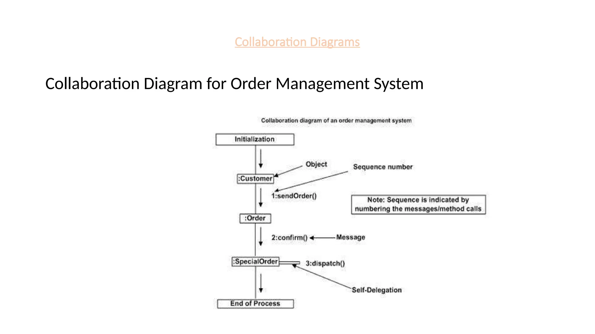
Collaboration Diagrams
Collaboration diagram:
Thesecond interaction diagram is the collaboration diagram.
The collaboration diagram shows the object organization.
If the time sequence is important, then the sequence diagram is used.
If organization is required, then collaboration diagram is used.
Interaction diagrams can be used
• To model the flow of control by time sequence.
• To model the flow of control by structural organizations.
• For forward engineering and reverse engineering.
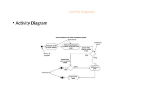
Activity Diagrams
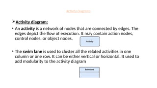
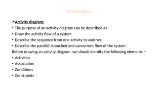
Activity diagram:
Activitydiagram is another important diagram in UML to describe the
dynamic aspects of the system.
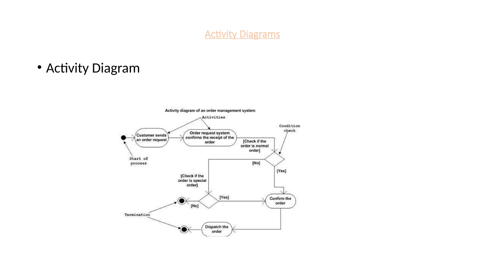
Activity diagram is basically a flowchart to represent the flow from one
activity to another activity. The activity can be described as an
operation of the system.
The control flow is drawn from one operation to another. This flow can
be sequential, branched, or concurrent.
44.
Activity Diagrams
Activity diagram:
•An activity is a network of nodes that are connected by edges. The
edges depict the flow of execution. It may contain action nodes,
control nodes, or object nodes.
• The swim lane is used to cluster all the related activities in one
column or one row. It can be either vertical or horizontal. It used to
add modularity to the activity diagram
45.
Activity Diagrams
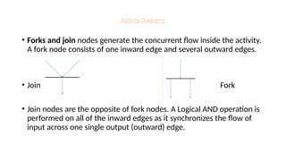
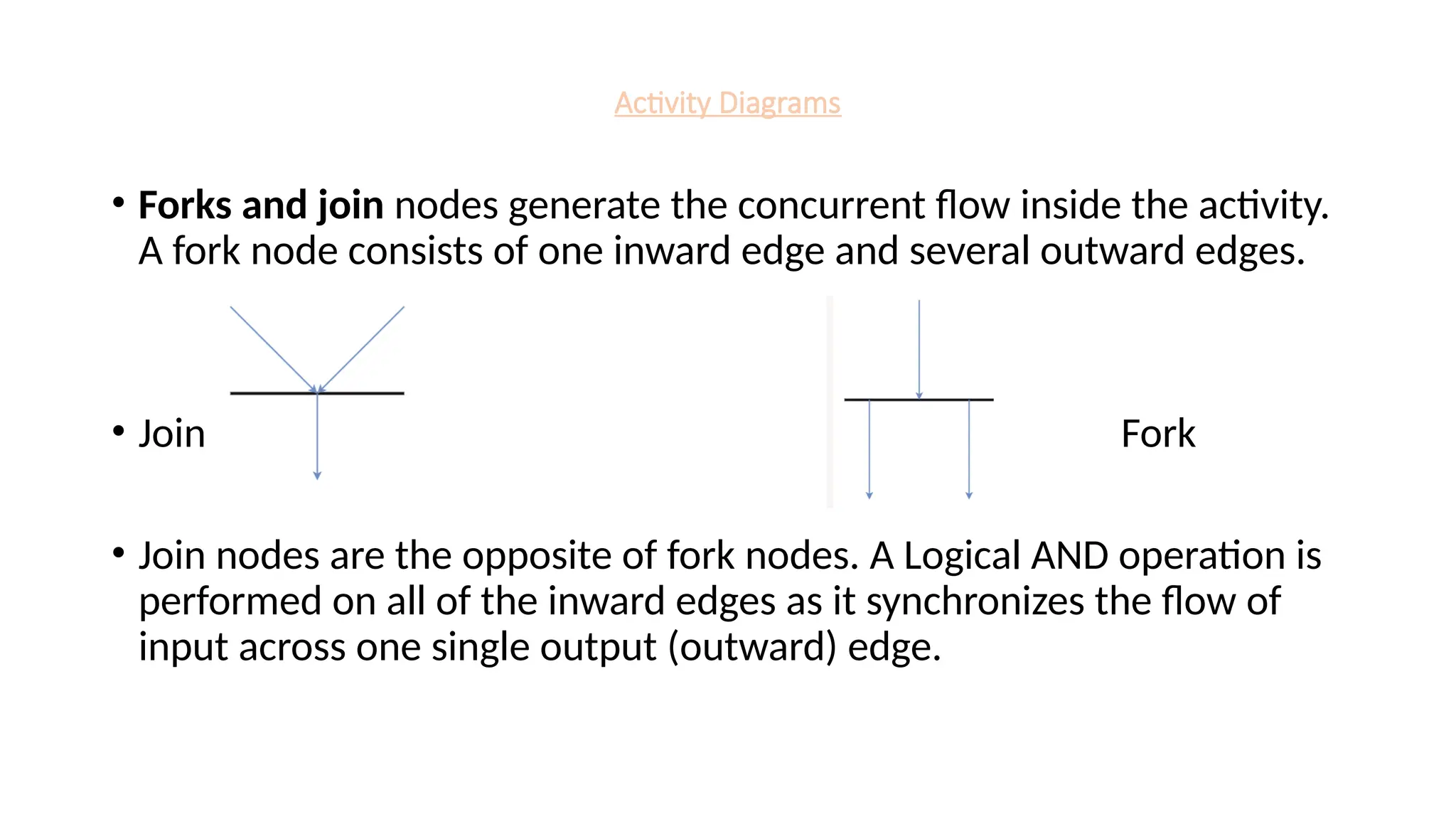
• Forksand join nodes generate the concurrent flow inside the activity.
A fork node consists of one inward edge and several outward edges.
• Join Fork
• Join nodes are the opposite of fork nodes. A Logical AND operation is
performed on all of the inward edges as it synchronizes the flow of
input across one single output (outward) edge.
46.
Activity Diagrams
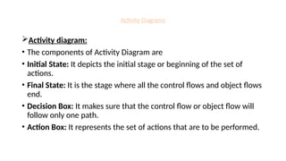
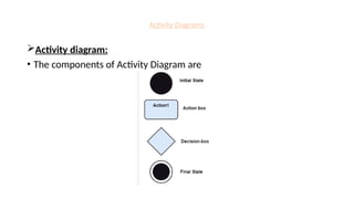
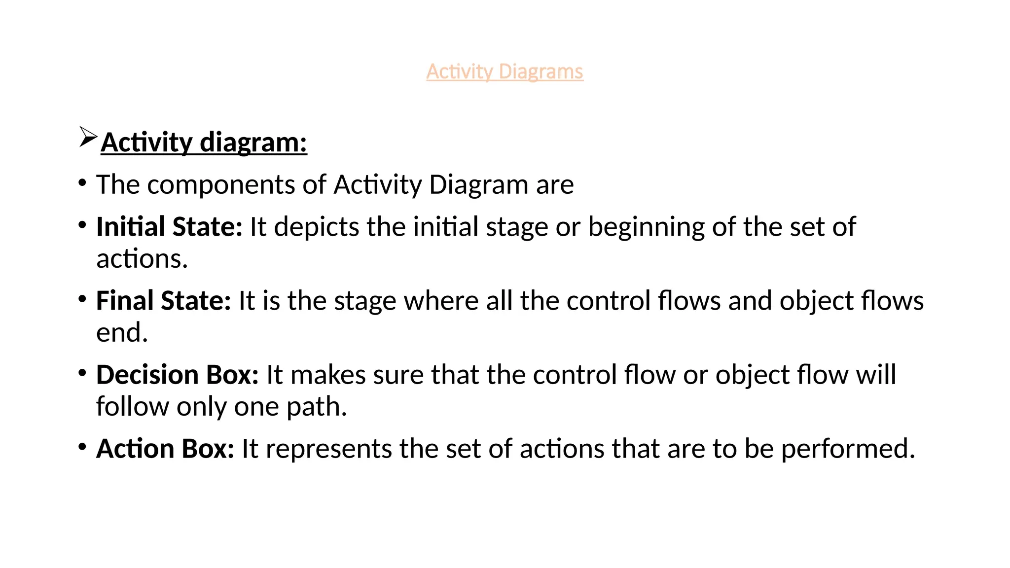
Activity diagram:
•The components of Activity Diagram are
• Initial State: It depicts the initial stage or beginning of the set of
actions.
• Final State: It is the stage where all the control flows and object flows
end.
• Decision Box: It makes sure that the control flow or object flow will
follow only one path.
• Action Box: It represents the set of actions that are to be performed.
Activity Diagrams
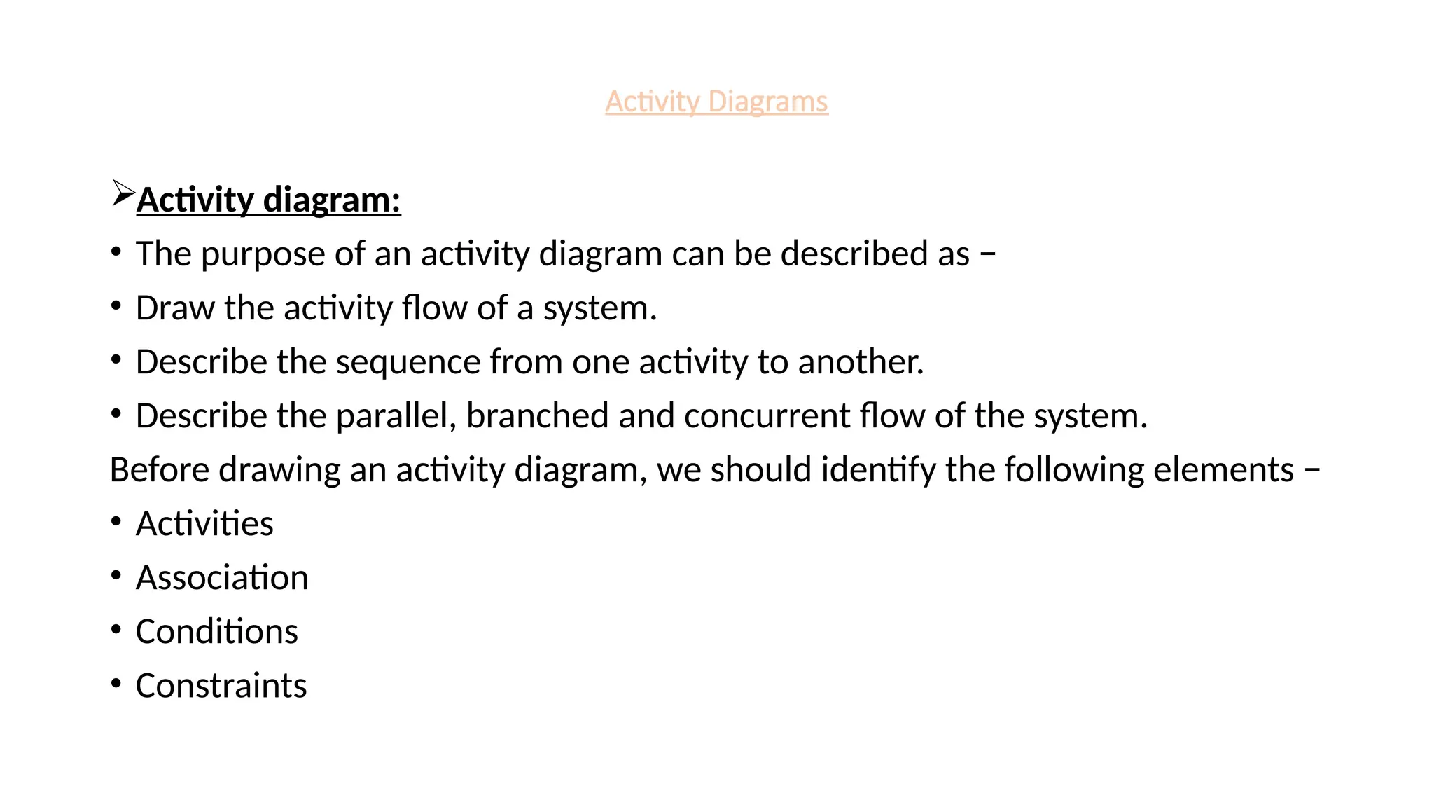
Activity diagram:
•The purpose of an activity diagram can be described as −
• Draw the activity flow of a system.
• Describe the sequence from one activity to another.
• Describe the parallel, branched and concurrent flow of the system.
Before drawing an activity diagram, we should identify the following elements −
• Activities
• Association
• Conditions
• Constraints
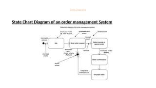
State Diagrams
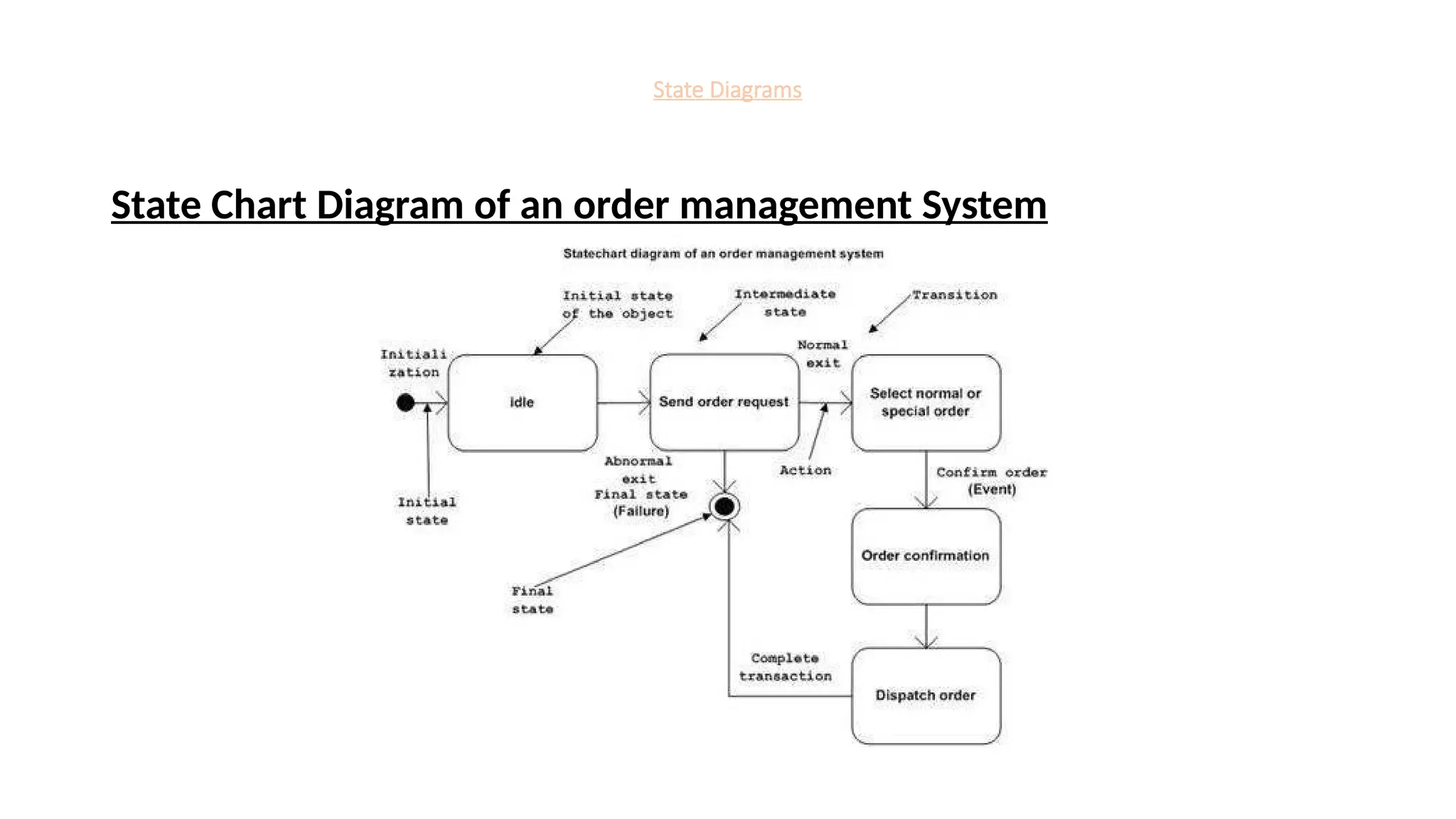
State chartdiagram:
• It describes different states of a component in a system. The states are
specific to a component/object of a system.
• A State chart diagram describes a state machine. State machine can be
defined as a machine which defines different states of an object and these
states are controlled by external or internal events.
The main purposes of using State chart diagrams
• To model the dynamic aspect of a system.
• To model the life time of a reactive system.
• To describe different states of an object during its life time.
• Define a state machine to model the states of an object.
State Diagrams
State chartdiagram:
• The main usage can be described as
• To model the object states of a system.
• To model the reactive system. Reactive system consists of reactive
objects.
• To identify the events responsible for state changes.
• Forward and reverse engineering
53.
Component Diagrams
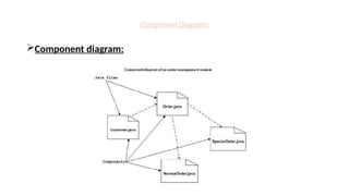
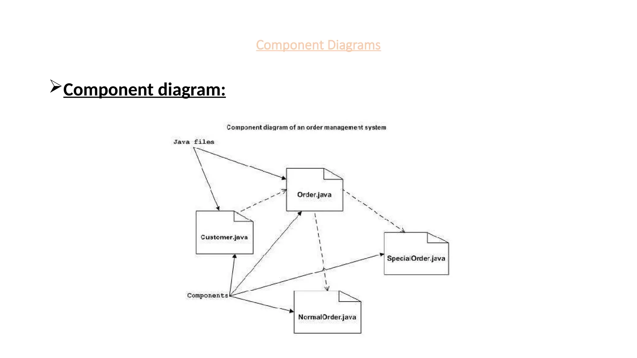
Component diagram:
Componentdiagrams are used to model the physical aspects of a
system.
Physical aspects are the elements such as executables, libraries, files,
documents, etc.
Component diagrams are used to visualize the organization and
relationships among components in a system. These diagrams are also
used to make executable systems.
54.
Component Diagrams
Component diagram:
•The purpose of the component diagram can be summarized as −
• Visualize the components of a system.
• Construct executables by using forward and reverse engineering.
• Describe the organization and relationships of the components.
55.
Component Diagrams
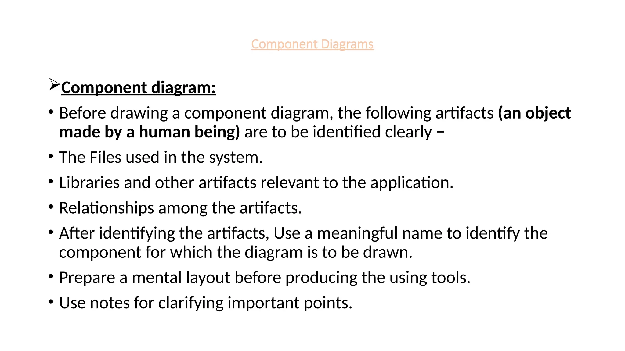
Component diagram:
•Before drawing a component diagram, the following artifacts (an object
made by a human being) are to be identified clearly −
• The Files used in the system.
• Libraries and other artifacts relevant to the application.
• Relationships among the artifacts.
• After identifying the artifacts, Use a meaningful name to identify the
component for which the diagram is to be drawn.
• Prepare a mental layout before producing the using tools.
• Use notes for clarifying important points.
Component Diagrams
Component diagram:
•Component diagrams can be used to −
• Model the components of a system.
• Model the database schema.
• Model the executables of an application.
• Model the system's source code
58.
Deployment Diagrams
Deployment diagram:
Deploymentdiagrams are used to visualize the topology of the physical
components of a system.
Deployment diagrams are used to describe the static deployment view of
a system. Deployment diagrams consist of nodes and their relationships.
The purpose of deployment diagrams can be described as
• Visualize the hardware topology of a system.
• Describe the hardware components used to deploy software
components.
• Describe the runtime processing nodes
59.
Deployment Diagrams
• Anefficient deployment diagram is very important as it controls the
following parameters −
• Performance
• Scalability
• Maintainability
• Portability
Before drawing a deployment diagram, the following artifacts should be
identified −
• Nodes
• Relationships among nodes
60.
Deployment Diagrams
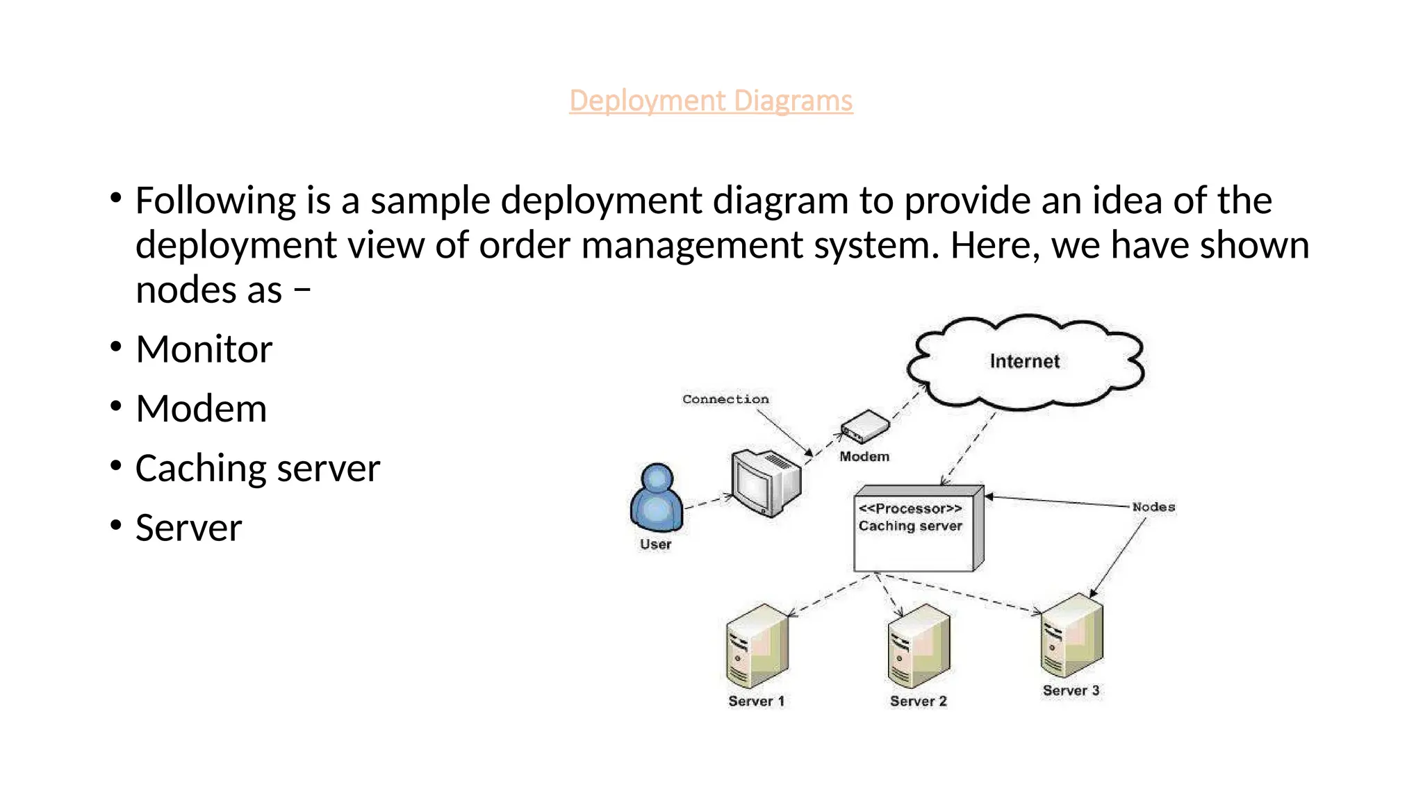
• Followingis a sample deployment diagram to provide an idea of the
deployment view of order management system. Here, we have shown
nodes as −
• Monitor
• Modem
• Caching server
• Server
61.
Deployment Diagrams
Deployment diagramscan be used −
• To model the hardware topology of a system.
• To model the embedded system.
• To model the hardware details for a client/server system.
• To model the hardware details of a distributed application.
• For Forward and Reverse engineering.
62.
Architecture of UML
Architectureof UML
• Software architecture provides a basic design of a complete software
system.
• It is a big picture or overall structure of the whole system, how
everything works together.
• A clear architecture will help to achieve quality in the software with a
well-designed structure using principles like separation of concerns;
the system becomes easier to maintain, reuse, and adapt.
• The software architecture is useful to people such as software
developers, the project manager, the client, and the end-user
63.
Architecture of UML
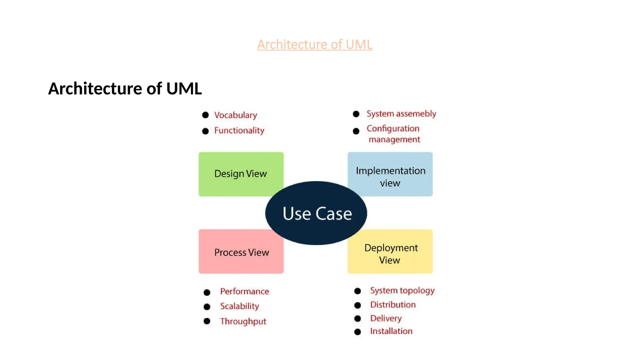
•Architecture of UML
• It can be best understood as a collection of five views:
• Use case view
• Design view
• Implementation view
• Process view
• Development view
Architecture of UML
Architectureof UML
Use case view
• It is a view that shows the functionality of the system as perceived by external
actors. It reveals the requirements of the system.
• With UML, it is easy to capture the static aspects of this view in the use case
diagrams, dynamic aspects are captured in interaction diagrams, state chart
diagrams, and activity diagrams.
Design View
• It is a view that shows how the functionality is designed inside the system in terms
of static structure and dynamic behaviour.
• It captures the vocabulary of the problem space and solution space.
• With UML, it represents the static aspects of this view in class and object
diagrams.
66.
Architecture of UML
Architectureof UML
Implementation View
• It is the view that represents the organization of the core components and files.
• It primarily addresses the configuration management of the system releases.
• With UML, its static aspects are expressed in component diagrams, and the dynamic
aspects are captured in interaction diagrams, state chart diagrams, and activity diagrams.
Process View
• It is the view that demonstrates the concurrency of the system.
• It incorporates the threads and processes that make concurrent system and synchronized
mechanisms.
• It primarily addresses the system's scalability, throughput, and performance.
• Its static and dynamic aspects are expressed the same way as the design view but focus
more on the active classes that represent these threads and processes.
67.
Architecture of UML
Architectureof UML
Deployment View
• It is the view that shows the deployment of the system in terms of
physical architecture.
• It includes the nodes, which form the system hardware topology
where the system will be executed.
• It primarily addresses the distribution, delivery, and installation of the
parts that build the physical system.
68.
Common Mechanism inUML
• Notes
• Stereotypes, tagged values, and constraints
• Modelling comments
• Modelling new building blocks
• Modelling new properties
• Modelling new semantics
• Extending the UML
The UML is made simpler by the presence of 4 common mechanisms.
• Specifications, Adornments, common divisions and extensibility
mechanism.
69.
Common Mechanism inUML
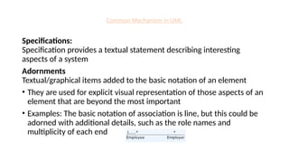
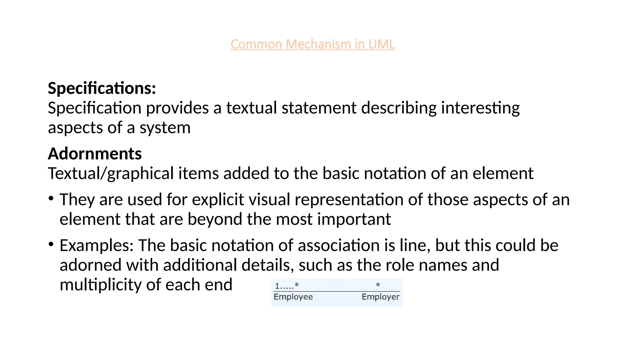
Specifications:
Specification provides a textual statement describing interesting
aspects of a system
Adornments
Textual/graphical items added to the basic notation of an element
• They are used for explicit visual representation of those aspects of an
element that are beyond the most important
• Examples: The basic notation of association is line, but this could be
adorned with additional details, such as the role names and
multiplicity of each end
70.
Common Mechanism inUML
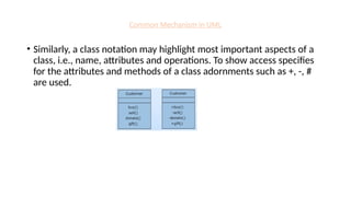
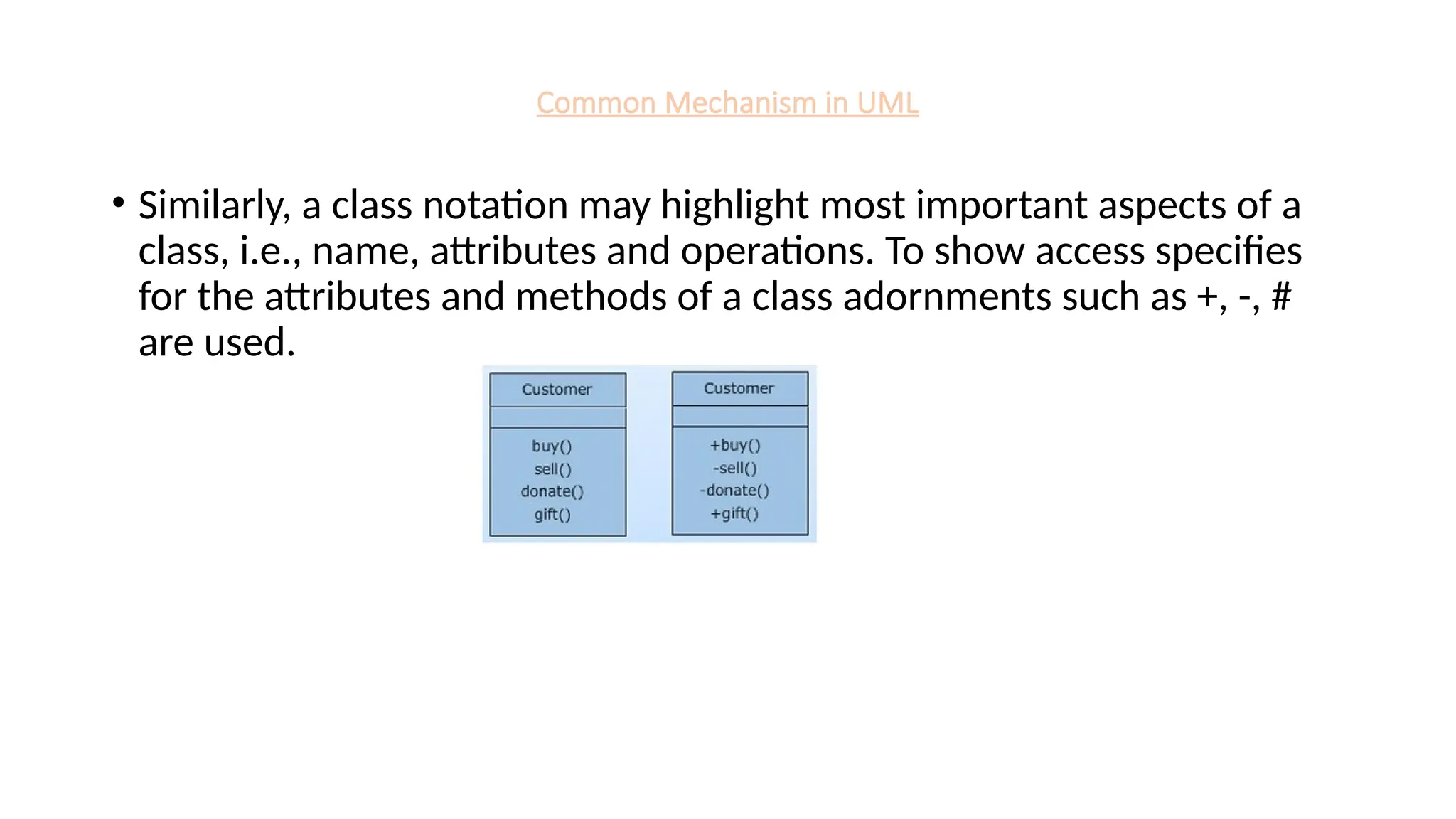
• Similarly, a class notation may highlight most important aspects of a
class, i.e., name, attributes and operations. To show access specifies
for the attributes and methods of a class adornments such as +, -, #
are used.
71.
Common Mechanism inUML
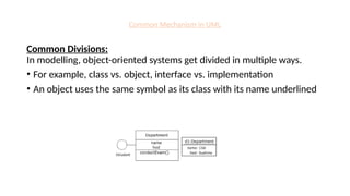
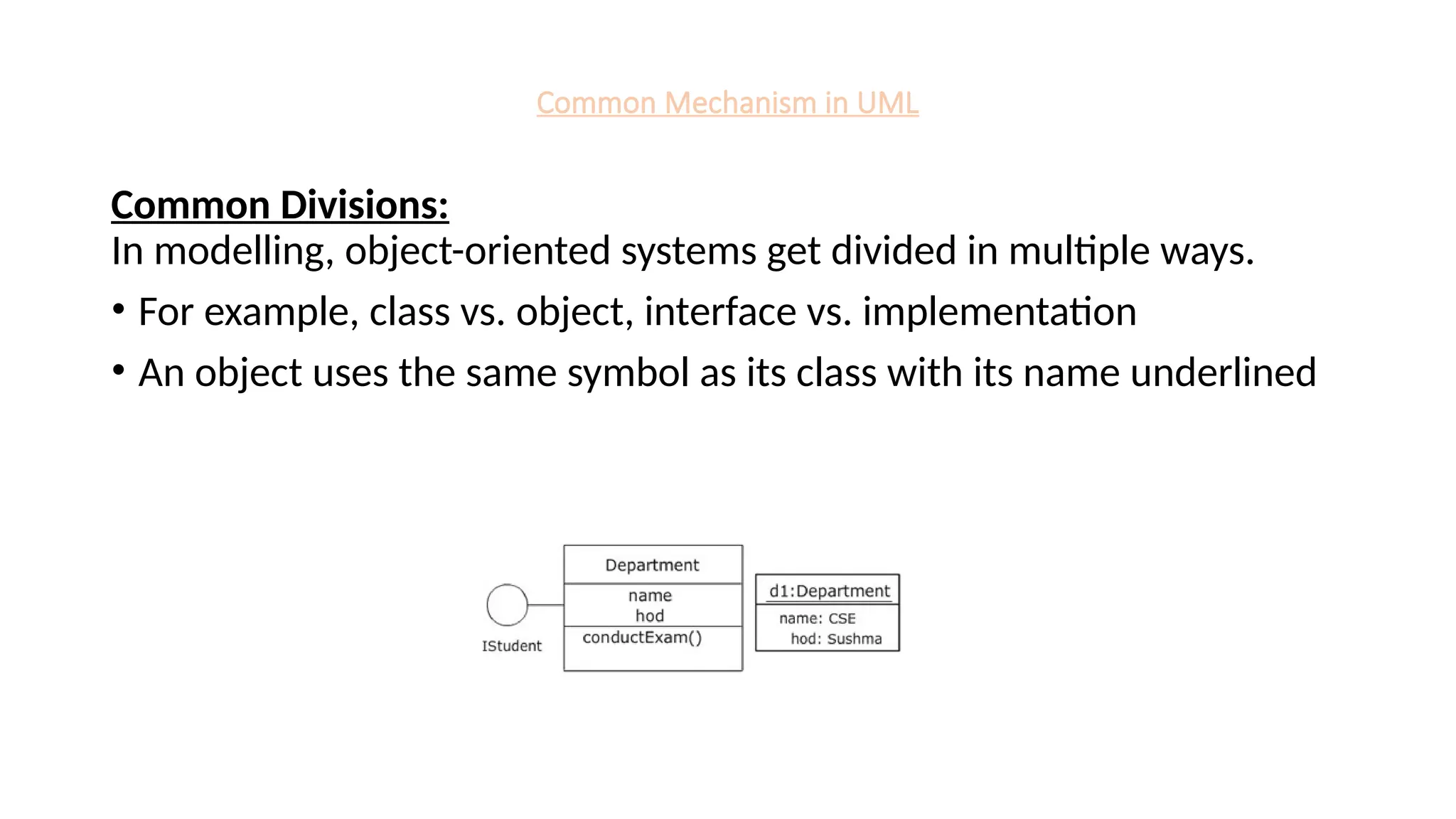
Common Divisions:
In modelling, object-oriented systems get divided in multiple ways.
• For example, class vs. object, interface vs. implementation
• An object uses the same symbol as its class with its name underlined
72.
Common Mechanism inUML
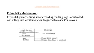
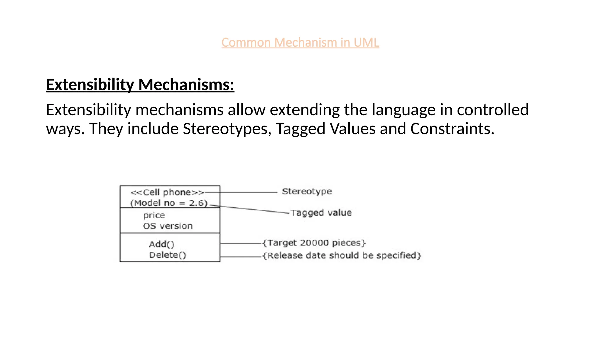
Extensibility Mechanisms:
Extensibility mechanisms allow extending the language in controlled
ways. They include Stereotypes, Tagged Values and Constraints.
73.
Common Mechanism inUML
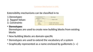
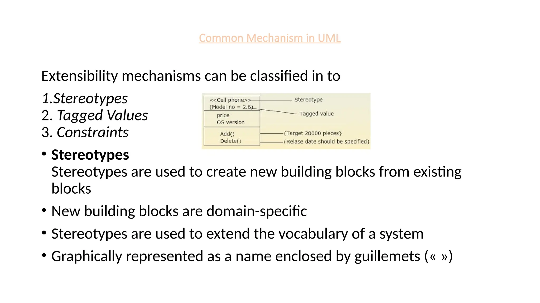
Extensibility mechanisms can be classified in to
1.Stereotypes
2. Tagged Values
3. Constraints
• Stereotypes
Stereotypes are used to create new building blocks from existing
blocks
• New building blocks are domain-specific
• Stereotypes are used to extend the vocabulary of a system
• Graphically represented as a name enclosed by guillemets (« »)
74.
Common Mechanism inUML
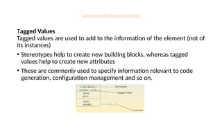
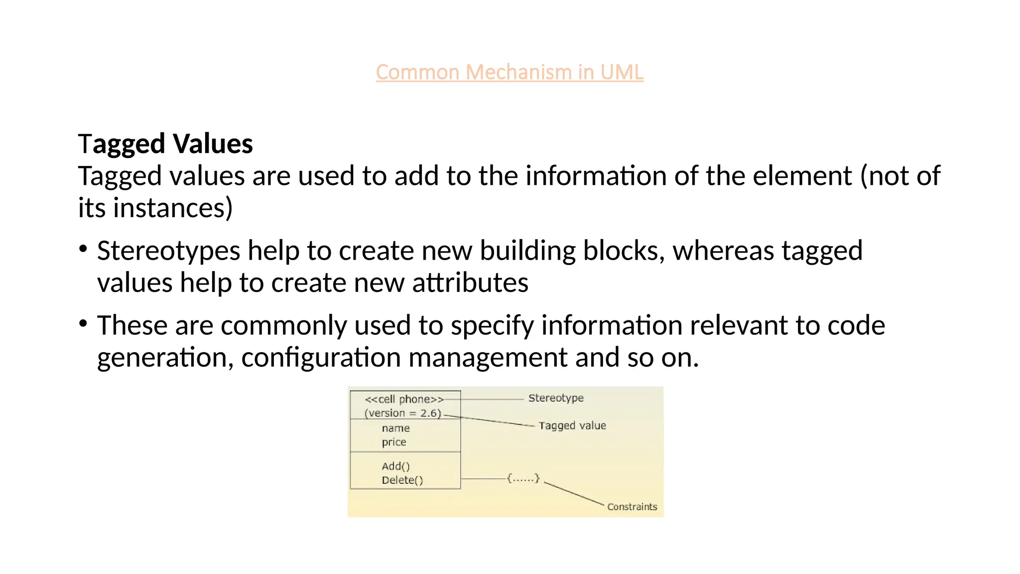
Tagged Values
Tagged values are used to add to the information of the element (not of
its instances)
• Stereotypes help to create new building blocks, whereas tagged
values help to create new attributes
• These are commonly used to specify information relevant to code
generation, configuration management and so on.
75.
Common Mechanism inUML
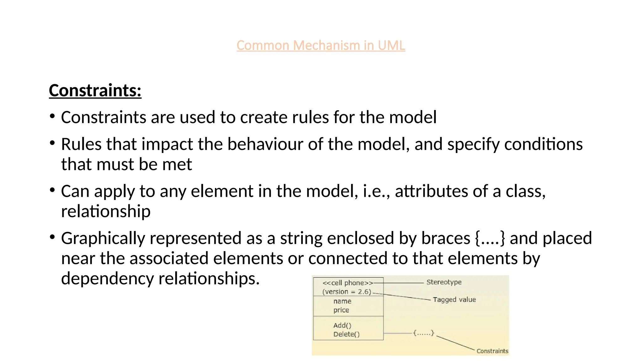
Constraints:
• Constraints are used to create rules for the model
• Rules that impact the behaviour of the model, and specify conditions
that must be met
• Can apply to any element in the model, i.e., attributes of a class,
relationship
• Graphically represented as a string enclosed by braces {....} and placed
near the associated elements or connected to that elements by
dependency relationships.


![RTP_AR_Basic_Learners' Workbook_KS2 [FOR REPRODUCTION] (1).pdf](https://cdn.slidesharecdn.com/ss_thumbnails/rtparbasiclearnersworkbookks2forreproduction1-251016024943-e51a16ac-thumbnail.jpg?width=600ounds&width=560&fit=bounds)


![Agentic Systems and Compliance - A brief intro [1.2]](https://cdn.slidesharecdn.com/ss_thumbnails/agenticsystemsandcompliace-1-251018025303-958a42ec-thumbnail.jpg?width=600ounds&width=560&fit=bounds)


