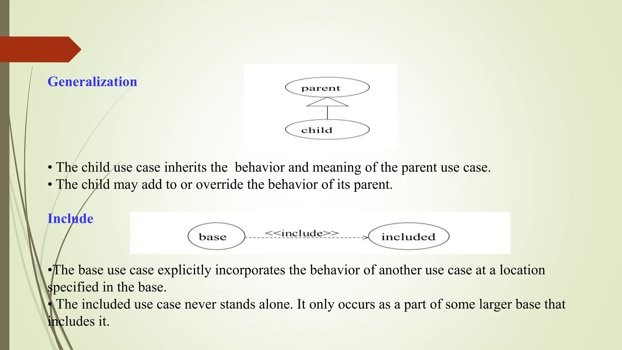
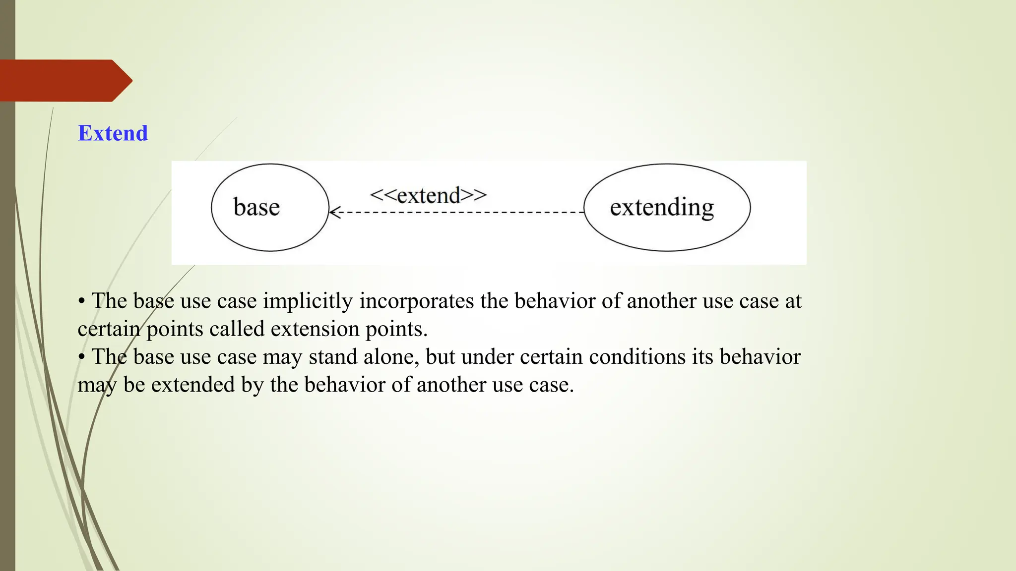
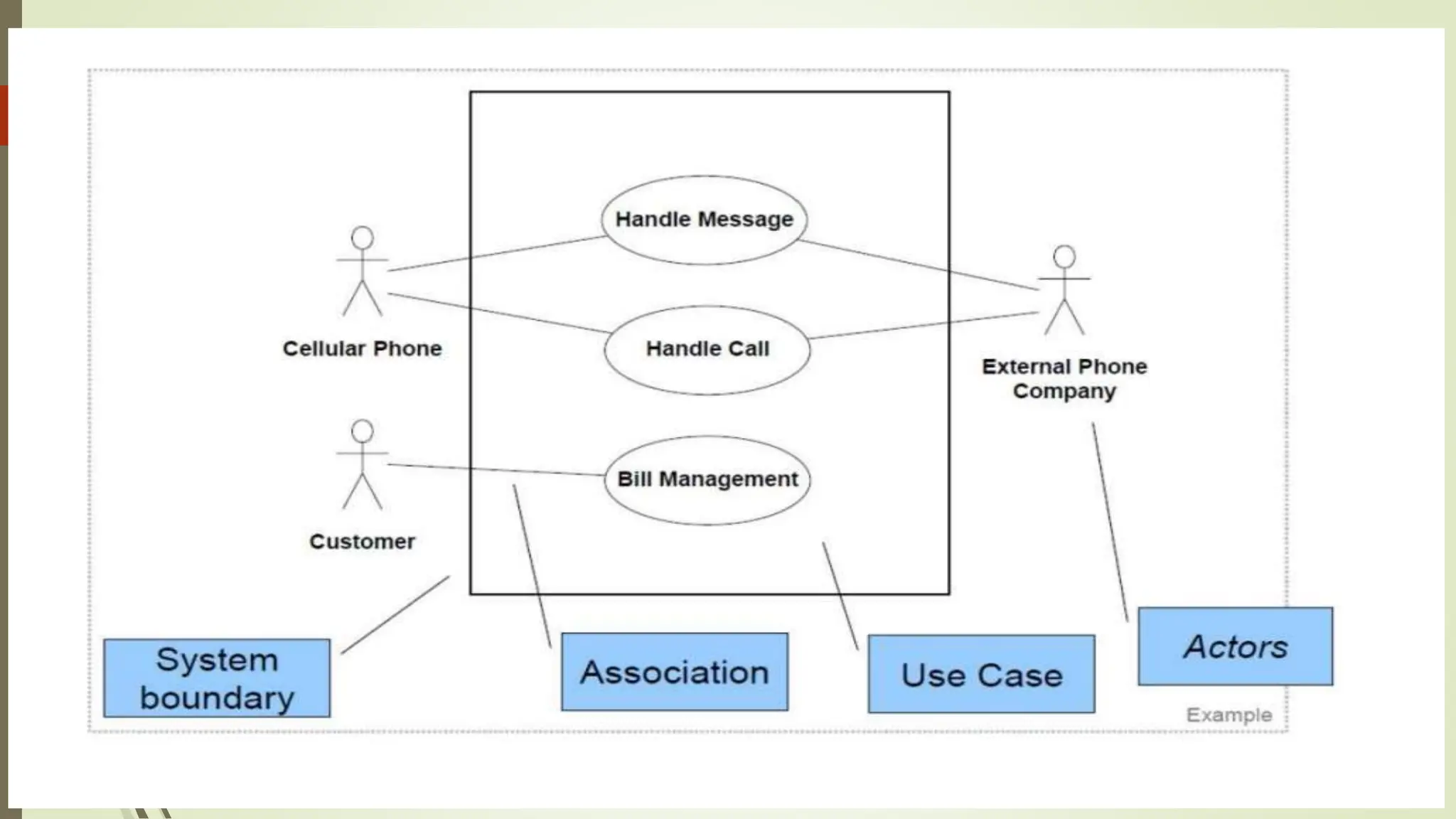
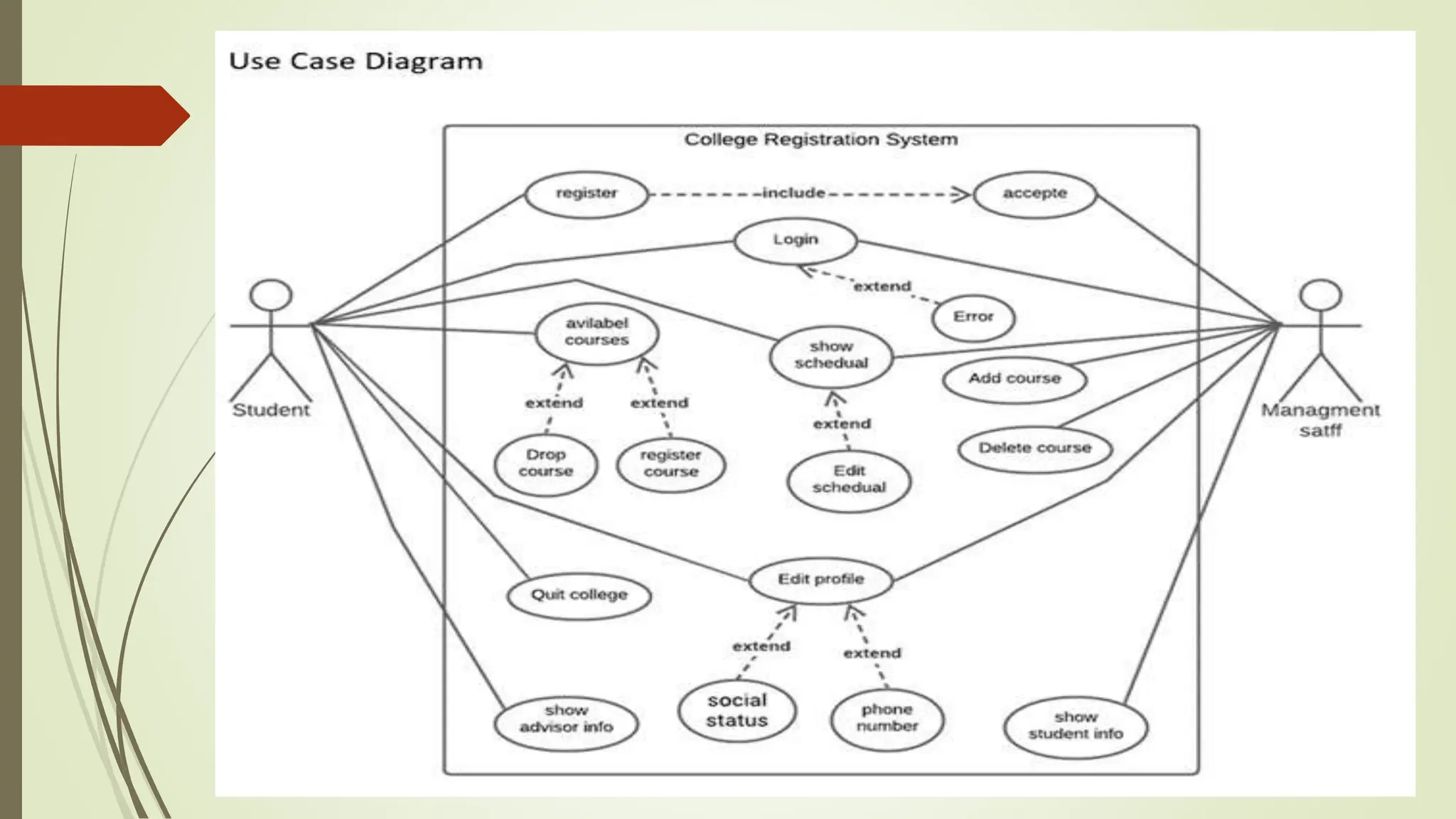
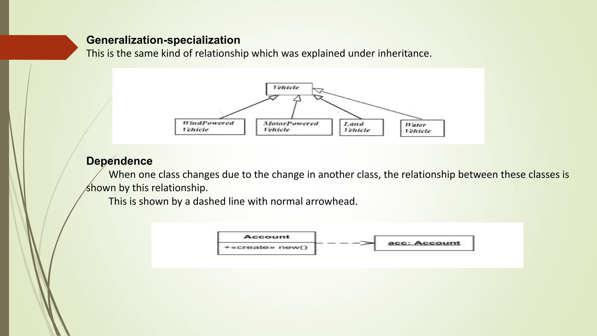
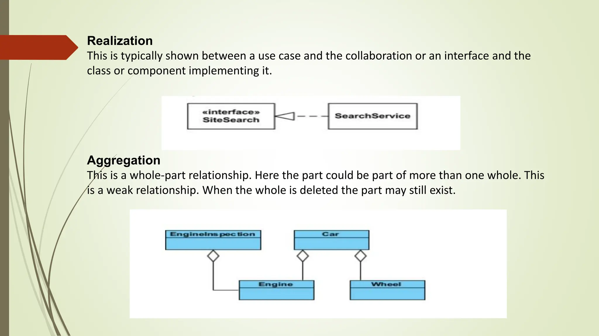
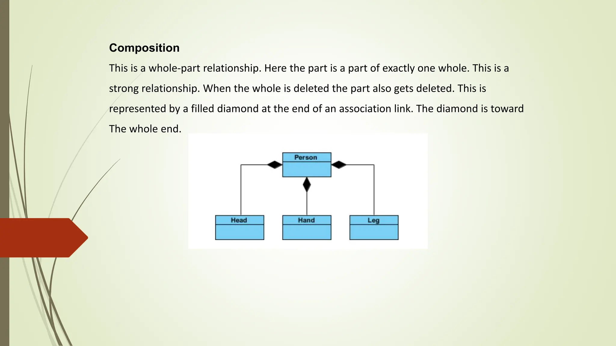
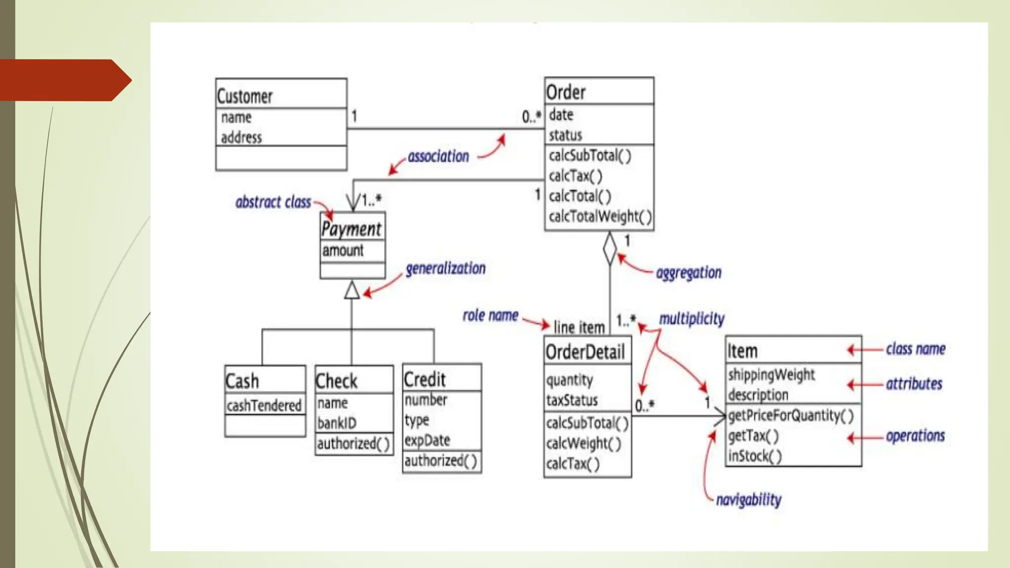
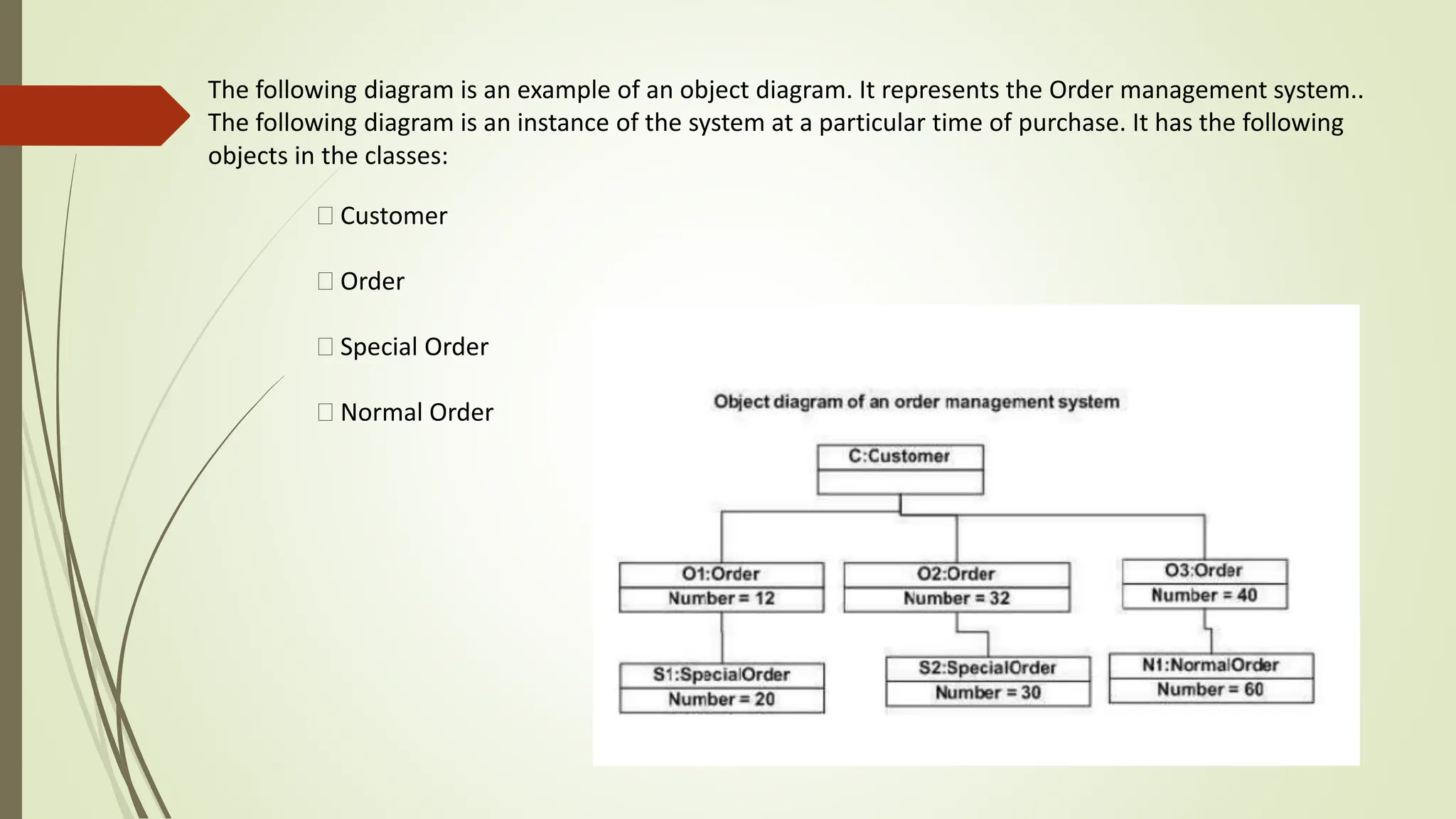
KEMBAR78
Unified Modeling Language and Examples .pptx
UNIT 3
OBJECT ORIENTED CONCEPTS
Introduction to OO concepts, UML Use Case Diagram-Include Extend and
Generalization, Class Diagram-Aggregation and Composition, Object Diagram-
Component Diagram-Sequence and Collaboration diagram-Deployment diagram-
Activity diagram-Package diagram-Design with examples of UML diagrams.
Introduction to OO concepts
Basic characteristics of OO System:
Objects
Attributes
Behaviour
Class
Methods
Message
Features of Object-Oriented System
Encapsulation
Encapsulation is simply the combination of process and data into a single entity.
Abstraction
It is a process of taking or selecting necessary method and attributes to specify the object. It focuses on essential
characteristics of an object.
Inheritance
Inheritance allows to create sub-classes from an existing class by inheriting the attributes and/or operations of
existing classes.
Polymorphism
Polymorphism is the ability to take on many different forms. It applies to both objects and operations.
Relationships
All the classes in the system are related with each other. The objects do not exist in isolation, they exist in
relationship with other objects.
There are three types of object relationships −
• Aggregation − It indicates relationship between a whole and its parts.
• Association − In this, two classes are related or connected in some way such as one class works with
another to perform a task or one class acts upon other class.
• Generalization − The child class is based on parent class. It indicates that two classes are similar but
have some differences.
Unified Modeling Language (UML)
 Unified Modeling Language (UML) is a standardized general-purpose modeling language
in the field of object-oriented software engineering.
 It lets you to model processes, software, and systems to express the design of system
architecture.
 It is a standard language for designing and documenting a system in an object oriented
Manner.
 UML includes a set of graphic notation techniques to create visual models of object-
oriented software systems.
UML is made up of −
• Diagrams − It is a pictorial representations of process, system, or some part of it.
• Notations − It consists of elements that work together in a diagram such as
connectors, symbols, notes , etc.
UML diagrams represent two different views of a system model:
Static (or structural) view
This view emphasizes the static structure of the system using objects, attributes, operations,
and relationships.
Ex: Class diagram, Composite Structure diagram.
Dynamic (or behavioral) view
This view emphasizes the dynamic behavior of the system by showing collaborations
among objects and changes to the internal states of objects.
Ex: Sequence diagram, Activity diagram, State Machine diagram.
Use Case Diagrams
 A use case diagram is a way to summarize details of a system and the users within that system(also known as actors) and
their interactions with the system.
 To build one, you'll use a set of specialized symbols and connectors
USE CASE
 A use case is a methodology used in system analysis to identify, clarify and organize system requirements.
 Describes the system's actions from a the point of view of a user
 A sequence of events involving
 Specifies one aspect of the behavior of a system, without specifying the structure of the system
Use Case Descriptions
• actors -something with a behavior or role, e.g., a person, another system, organization.
• scenario - a specific sequence of actions and interactions between actors and the system.
• use case - a collection of related success and failure scenarios, describing actors using the system to
support a goal.
What is an Actor?
• Include all user roles that interact with the system
• Include system components only if they responsible for initiating/triggering a use case.
For example, a timer that triggers sending of an e-mail reminder
• primary - a user whose goals are fulfilled by the system
• supporting - provides a service (e.g., info) to the system
• offstage - has an interest in the behavior but is not primary or supporting, e.g., government
Elements of use case diagram:
Linking Use Cases
• Association relationships
• Generalization relationships
One element (child) "is based on" another element (parent)
• Include relationships
One use case (base) includes the functionality of another (inclusion case) ,Supports re-use of
functionality
• Extend relationships
One use case (extension) extends the behavior of another (base)
Generalization
• The child use case inherits the behavior and meaning of the parent use case.
• The child may add to or override the behavior of its parent.
Include
•The base use case explicitly incorporates the behavior of another use case at a location
specified in the base.
• The included use case never stands alone. It only occurs as a part of some larger base that
includes it.
Extend
• The base use case implicitly incorporates the behavior of another use case at
certain points called extension points.
• The base use case may stand alone, but under certain conditions its behavior
may be extended by the behavior of another use case.
CLASS DIAGRAM
 This is the most common diagram used in the UML.
 The class diagram shows the different classes involved and the relationships between
different classes.
 The class also shows the details like the attributes and the operations carried out by that
class.
 The relationships describe the details like visibility, multiplicity etc.,
 The class diagram consists of classes, interfaces, relationships and collaborations.
Need For Class Diagram:
o The purpose of a class diagram is to model the static view of an application.
o This diagram helps in the analysis and design of the static elements of an application.
o They describe the responsibilities of the system from the implementation point of view.
o This diagram can help in the development of the component and deployment diagrams.
ELEMENTS OF CLASS DIAGRAM
Class
A class is represented as a rectangle with three compartments.
 The top compartment is used to write the name of the class.
 The middle compartment is used for listing the attributes of that class
 The last compartment is used to list the operations of that class.
Sometimes if there is no need to show all the attributes and operations simple write the class name in a
rectangle which is not compartmentalized.
Sometimes more compartments can also be used. In this case the compartments are named and the
corresponding responsibilities are written below the compartment name.
Visibility
There are three types of visibility modes available.
public (+ for public)
private (- for private )
protected (# for protected).
Multiplicity
The classes involved in a relationship may have a:
one-to- one
one-to-many
many-to-many.
Association
It is the simplest relationship that can exist between a pair of classes. The association can have
multiplicity.
This relationship can also be identified by a name.
It is shown by a plain line joining two classes.
Generalization-specialization
This is the same kind of relationship which was explained under inheritance.
Dependence
When one class changes due to the change in another class, the relationship between these classes is
shown by this relationship.
This is shown by a dashed line with normal arrowhead.
Realization
This is typically shown between a use case and the collaboration or an interface and the
class or component implementing it.
Aggregation
This is a whole-part relationship. Here the part could be part of more than one whole. This
is a weak relationship. When the whole is deleted the part may still exist.
Composition
This is a whole-part relationship. Here the part is a part of exactly one whole. This is a
strong relationship. When the whole is deleted the part also gets deleted. This is
represented by a filled diamond at the end of an association link. The diamond is toward
The whole end.
Association vs Aggregation vs Composition
Aggregation and Composition are subsets of association meaning they are specific cases of
association. In both aggregation and composition object of one class "owns" object of another
class. But there is a subtle difference:
Aggregation implies a relationship where the child can exist independently of the
parent. Example: Class (parent) and Student (child). Delete the Class and theStudents
still exist.
Composition implies a relationship where the child cannot exist independent of the
parent. Example: House (parent) and Room (child). Rooms don't exist separate to a
House.
Object diagram
Objects are the real-world entities whose behavior is defined by the classes.
Object diagrams also represent the static view of a system but this static view is a snapshot of the
system at a particular moment.
Object diagrams are used to render a set of objects and their relationships as an instance. We cannot
define an object without its class. Object and class diagrams are somewhat similar.
Object diagrams are derived from class diagrams so object diagrams are dependent upon class
Diagrams
The purpose of the object diagram can be summarized as −
Forward and reverse engineering.
Object relationships of a system
Static view of an interaction.
Understand object behaviour and their relationship from practical perspective
How to Draw an Object Diagram?
An object diagram is an instance of a class diagram. It implies that an object diagram consists of instances of
things used in a class diagram.
In class diagram elements are in abstract form to represent the blue print and in object diagram the elements are
in concrete form to represent the real world object.
To capture a particular system, numbers of class diagrams are limited. However, if we consider object diagrams
then we can have unlimited number of instances, which are unique in nature.
It is clear that a single object diagram cannot capture all the necessary instances or rather cannot specify all the
objects of a system. Hence, the solution is −
• First, analyze the system and decide which instances have important data and
association.
• Second, consider only those instances, which will cover the functionality.
• Third, make some optimization as the number of instances are unlimited.
Before drawing an object diagram, the following things should be remembered and
understood clearly −
• Object diagrams consist of objects.
• The link in object diagram is used to connect objects.
• Objects and links are the two elements used to construct an object diagram
After this, the following things are to be decided before starting the construction of the diagram
−
The object diagram should have a meaningful name to indicate its purpose.
The most important elements are to be identified.
The association among objects should be clarified.
Values of different elements need to be captured to include in the object diagram.
Add proper notes at points where more clarity is required.
The following diagram is an example of an object diagram. It represents the Order management system..
The following diagram is an instance of the system at a particular time of purchase. It has the following
objects in the classes:
Customer
Order
Special Order
Normal Order
In a nutshell, it can be said that object diagrams are used for −
Making the prototype of a system.
Reverse engineering.
Modeling complex data structures.
 Understanding the system from practical perspective
The difference between the class and object diagram is that the class diagram mainly represents the bird's
eye view of a system which is also referred to as an abstract view. An object diagram describes the instance
of a class. It visualizes the particular part of a System.
The above UML object diagram contains two objects named Ferrari and BMW which belong to a class named as a Car. The
objects are nothing but real-world entities that are the instances of a class.

Unified Modeling Language and Examples .pptx

  • 1.
    UNIT 3 OBJECT ORIENTEDCONCEPTS Introduction to OO concepts, UML Use Case Diagram-Include Extend and Generalization, Class Diagram-Aggregation and Composition, Object Diagram- Component Diagram-Sequence and Collaboration diagram-Deployment diagram- Activity diagram-Package diagram-Design with examples of UML diagrams.
  • 2.
    Introduction to OOconcepts Basic characteristics of OO System: Objects Attributes Behaviour Class Methods Message
  • 3.
    Features of Object-OrientedSystem Encapsulation Encapsulation is simply the combination of process and data into a single entity. Abstraction It is a process of taking or selecting necessary method and attributes to specify the object. It focuses on essential characteristics of an object. Inheritance Inheritance allows to create sub-classes from an existing class by inheriting the attributes and/or operations of existing classes. Polymorphism Polymorphism is the ability to take on many different forms. It applies to both objects and operations.
  • 4.
    Relationships All the classesin the system are related with each other. The objects do not exist in isolation, they exist in relationship with other objects. There are three types of object relationships − • Aggregation − It indicates relationship between a whole and its parts. • Association − In this, two classes are related or connected in some way such as one class works with another to perform a task or one class acts upon other class. • Generalization − The child class is based on parent class. It indicates that two classes are similar but have some differences.
  • 6.
    Unified Modeling Language(UML)  Unified Modeling Language (UML) is a standardized general-purpose modeling language in the field of object-oriented software engineering.  It lets you to model processes, software, and systems to express the design of system architecture.  It is a standard language for designing and documenting a system in an object oriented Manner.  UML includes a set of graphic notation techniques to create visual models of object- oriented software systems.
  • 7.
    UML is madeup of − • Diagrams − It is a pictorial representations of process, system, or some part of it. • Notations − It consists of elements that work together in a diagram such as connectors, symbols, notes , etc. UML diagrams represent two different views of a system model: Static (or structural) view This view emphasizes the static structure of the system using objects, attributes, operations, and relationships. Ex: Class diagram, Composite Structure diagram. Dynamic (or behavioral) view This view emphasizes the dynamic behavior of the system by showing collaborations among objects and changes to the internal states of objects. Ex: Sequence diagram, Activity diagram, State Machine diagram.
  • 9.
    Use Case Diagrams A use case diagram is a way to summarize details of a system and the users within that system(also known as actors) and their interactions with the system.  To build one, you'll use a set of specialized symbols and connectors USE CASE  A use case is a methodology used in system analysis to identify, clarify and organize system requirements.  Describes the system's actions from a the point of view of a user  A sequence of events involving  Specifies one aspect of the behavior of a system, without specifying the structure of the system
  • 10.
    Use Case Descriptions •actors -something with a behavior or role, e.g., a person, another system, organization. • scenario - a specific sequence of actions and interactions between actors and the system. • use case - a collection of related success and failure scenarios, describing actors using the system to support a goal. What is an Actor? • Include all user roles that interact with the system • Include system components only if they responsible for initiating/triggering a use case. For example, a timer that triggers sending of an e-mail reminder • primary - a user whose goals are fulfilled by the system • supporting - provides a service (e.g., info) to the system • offstage - has an interest in the behavior but is not primary or supporting, e.g., government
  • 11.
    Elements of usecase diagram:
  • 12.
    Linking Use Cases •Association relationships • Generalization relationships One element (child) "is based on" another element (parent) • Include relationships One use case (base) includes the functionality of another (inclusion case) ,Supports re-use of functionality • Extend relationships One use case (extension) extends the behavior of another (base)
  • 13.
    Generalization • The childuse case inherits the behavior and meaning of the parent use case. • The child may add to or override the behavior of its parent. Include •The base use case explicitly incorporates the behavior of another use case at a location specified in the base. • The included use case never stands alone. It only occurs as a part of some larger base that includes it.
  • 14.
    Extend • The baseuse case implicitly incorporates the behavior of another use case at certain points called extension points. • The base use case may stand alone, but under certain conditions its behavior may be extended by the behavior of another use case.
  • 17.
    CLASS DIAGRAM  Thisis the most common diagram used in the UML.  The class diagram shows the different classes involved and the relationships between different classes.  The class also shows the details like the attributes and the operations carried out by that class.  The relationships describe the details like visibility, multiplicity etc.,  The class diagram consists of classes, interfaces, relationships and collaborations. Need For Class Diagram: o The purpose of a class diagram is to model the static view of an application. o This diagram helps in the analysis and design of the static elements of an application. o They describe the responsibilities of the system from the implementation point of view. o This diagram can help in the development of the component and deployment diagrams.
  • 18.
    ELEMENTS OF CLASSDIAGRAM Class A class is represented as a rectangle with three compartments.  The top compartment is used to write the name of the class.  The middle compartment is used for listing the attributes of that class  The last compartment is used to list the operations of that class.
  • 19.
    Sometimes if thereis no need to show all the attributes and operations simple write the class name in a rectangle which is not compartmentalized. Sometimes more compartments can also be used. In this case the compartments are named and the corresponding responsibilities are written below the compartment name. Visibility There are three types of visibility modes available. public (+ for public) private (- for private ) protected (# for protected).
  • 20.
    Multiplicity The classes involvedin a relationship may have a: one-to- one one-to-many many-to-many.
  • 21.
    Association It is thesimplest relationship that can exist between a pair of classes. The association can have multiplicity. This relationship can also be identified by a name. It is shown by a plain line joining two classes.
  • 22.
    Generalization-specialization This is thesame kind of relationship which was explained under inheritance. Dependence When one class changes due to the change in another class, the relationship between these classes is shown by this relationship. This is shown by a dashed line with normal arrowhead.
  • 23.
    Realization This is typicallyshown between a use case and the collaboration or an interface and the class or component implementing it. Aggregation This is a whole-part relationship. Here the part could be part of more than one whole. This is a weak relationship. When the whole is deleted the part may still exist.
  • 24.
    Composition This is awhole-part relationship. Here the part is a part of exactly one whole. This is a strong relationship. When the whole is deleted the part also gets deleted. This is represented by a filled diamond at the end of an association link. The diamond is toward The whole end.
  • 25.
    Association vs Aggregationvs Composition Aggregation and Composition are subsets of association meaning they are specific cases of association. In both aggregation and composition object of one class "owns" object of another class. But there is a subtle difference: Aggregation implies a relationship where the child can exist independently of the parent. Example: Class (parent) and Student (child). Delete the Class and theStudents still exist. Composition implies a relationship where the child cannot exist independent of the parent. Example: House (parent) and Room (child). Rooms don't exist separate to a House.
  • 27.
    Object diagram Objects arethe real-world entities whose behavior is defined by the classes. Object diagrams also represent the static view of a system but this static view is a snapshot of the system at a particular moment. Object diagrams are used to render a set of objects and their relationships as an instance. We cannot define an object without its class. Object and class diagrams are somewhat similar. Object diagrams are derived from class diagrams so object diagrams are dependent upon class Diagrams The purpose of the object diagram can be summarized as − Forward and reverse engineering. Object relationships of a system Static view of an interaction. Understand object behaviour and their relationship from practical perspective
  • 28.
    How to Drawan Object Diagram? An object diagram is an instance of a class diagram. It implies that an object diagram consists of instances of things used in a class diagram. In class diagram elements are in abstract form to represent the blue print and in object diagram the elements are in concrete form to represent the real world object. To capture a particular system, numbers of class diagrams are limited. However, if we consider object diagrams then we can have unlimited number of instances, which are unique in nature. It is clear that a single object diagram cannot capture all the necessary instances or rather cannot specify all the objects of a system. Hence, the solution is − • First, analyze the system and decide which instances have important data and association. • Second, consider only those instances, which will cover the functionality. • Third, make some optimization as the number of instances are unlimited.
  • 29.
    Before drawing anobject diagram, the following things should be remembered and understood clearly − • Object diagrams consist of objects. • The link in object diagram is used to connect objects. • Objects and links are the two elements used to construct an object diagram After this, the following things are to be decided before starting the construction of the diagram − The object diagram should have a meaningful name to indicate its purpose. The most important elements are to be identified. The association among objects should be clarified. Values of different elements need to be captured to include in the object diagram. Add proper notes at points where more clarity is required.
  • 30.
    The following diagramis an example of an object diagram. It represents the Order management system.. The following diagram is an instance of the system at a particular time of purchase. It has the following objects in the classes: Customer Order Special Order Normal Order
  • 31.
    In a nutshell,it can be said that object diagrams are used for − Making the prototype of a system. Reverse engineering. Modeling complex data structures.  Understanding the system from practical perspective The difference between the class and object diagram is that the class diagram mainly represents the bird's eye view of a system which is also referred to as an abstract view. An object diagram describes the instance of a class. It visualizes the particular part of a System.
  • 32.
    The above UMLobject diagram contains two objects named Ferrari and BMW which belong to a class named as a Car. The objects are nothing but real-world entities that are the instances of a class.