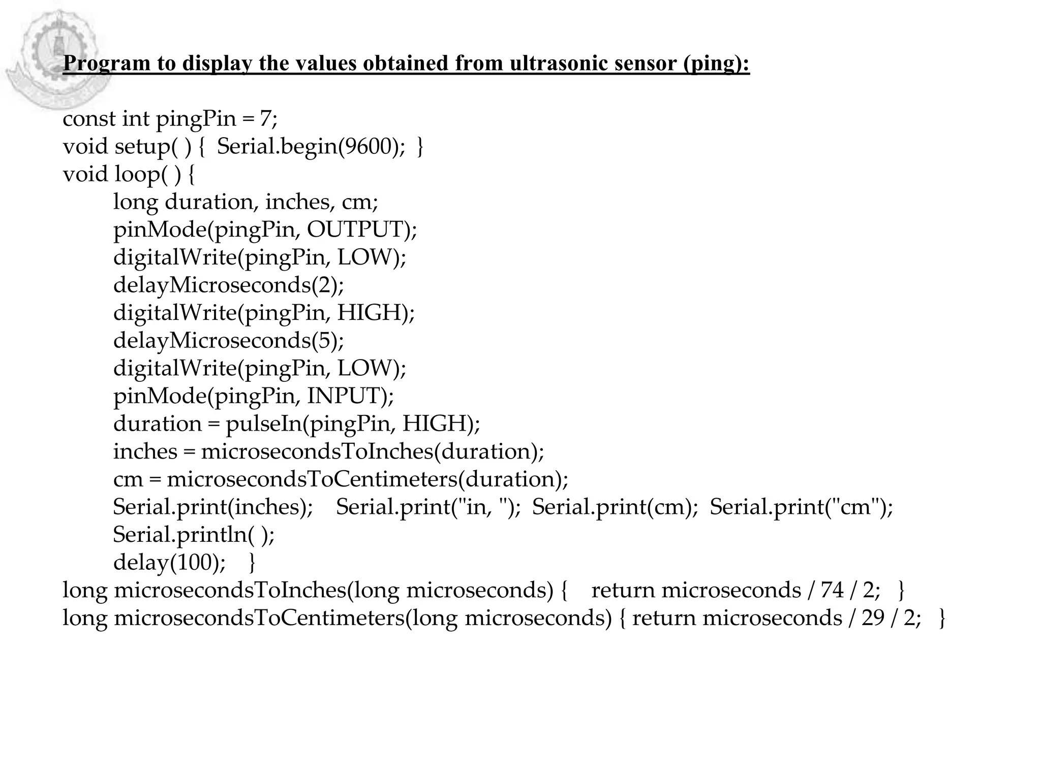
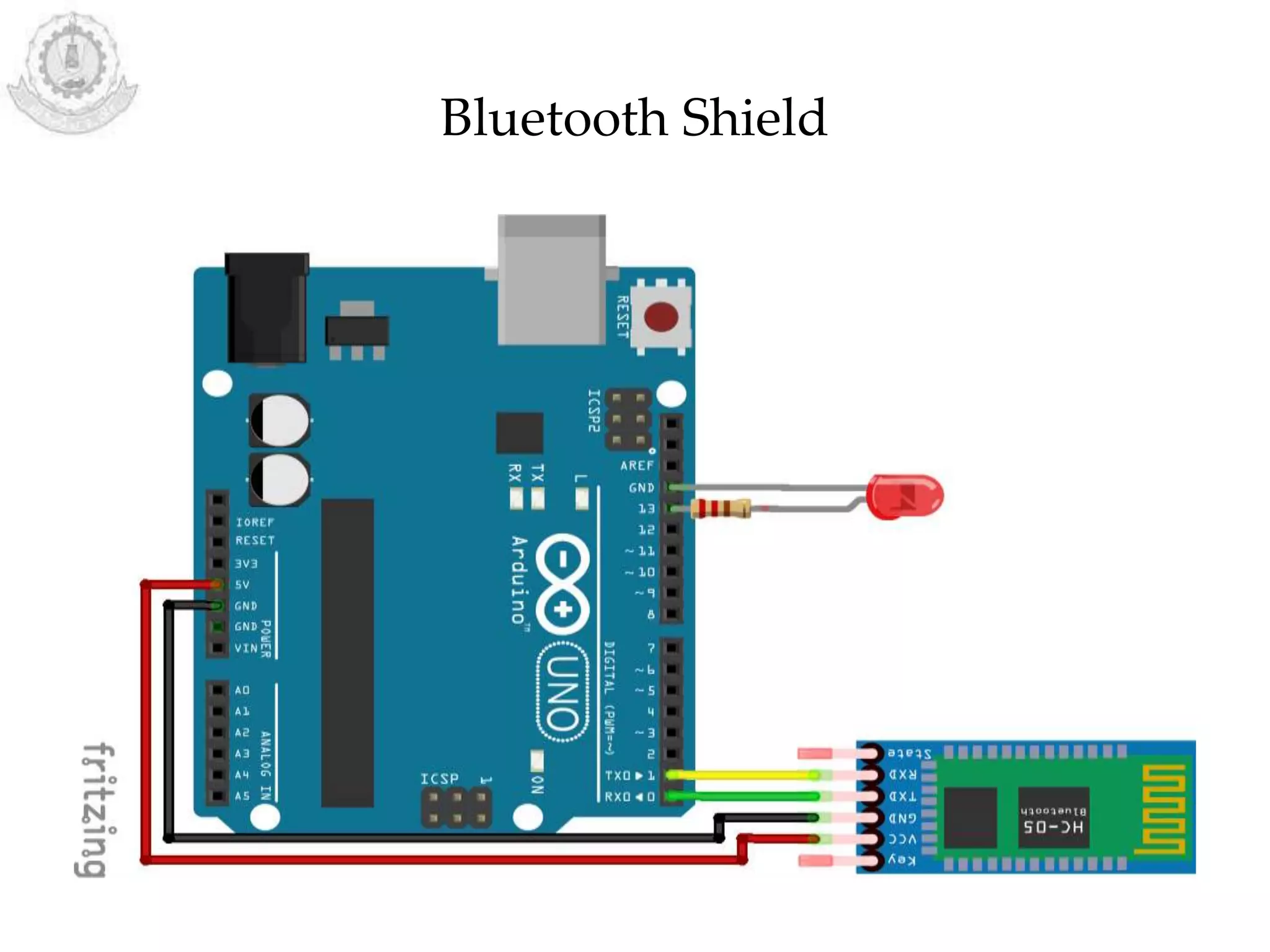
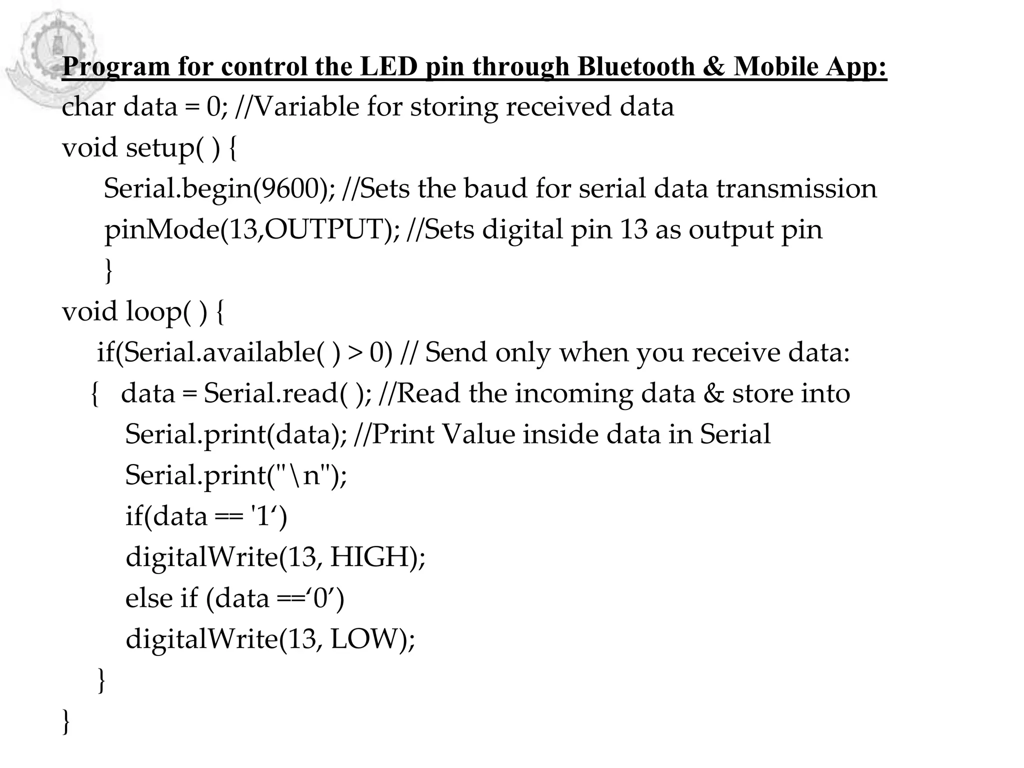
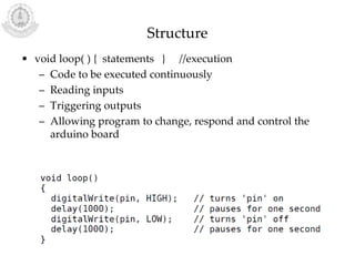
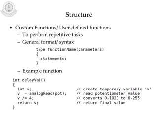
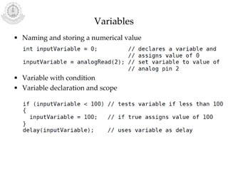
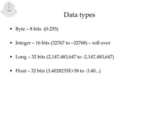
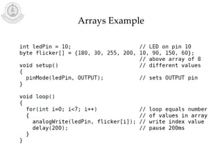
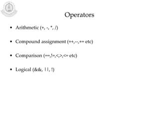
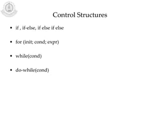
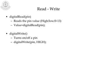
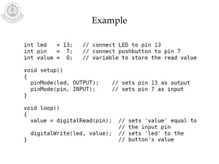
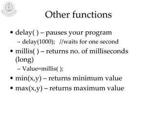
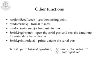
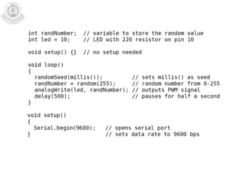
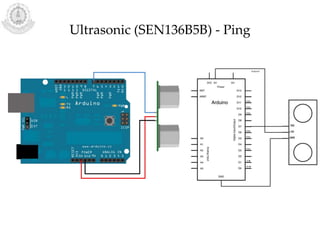
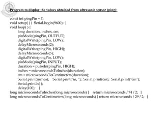
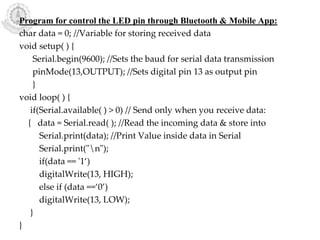
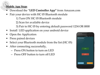
KEMBAR78
Arduino Programming | PPTX
ARDUINO PROGRAMMING
Dr.P.Karthikeyan
Associate Professor
Department of Information Technology
Thiagarajar College of Engineering
Madurai - 625 015
Structure
• void setup( ) { statements } //preparation
– Declaration of variables
– First function to run – run only once
– To set pinmode or initialize serial communication
– It must be present for the program to run
Structure
• void loop( ) { statements } //execution
– Code to be executed continuously
– Reading inputs
– Triggering outputs
– Allowing program to change, respond and control the
arduino board
Structure
• Custom Functions/ User-defined functions
– To perform repetitive tasks
– General format/ syntax
– Example function
Variables
• Naming and storing a numerical value
• Variable with condition
• Variable declaration and scope
Data types
• Byte – 8 bits (0-255)
• Integer – 16 bits (32767 to –32768) – roll over
• Long – 32 bits (2,147,483,647 to -2,147,483,647)
• Float – 32 bits (3.4028235E+38 to -3.40...)
Arrays
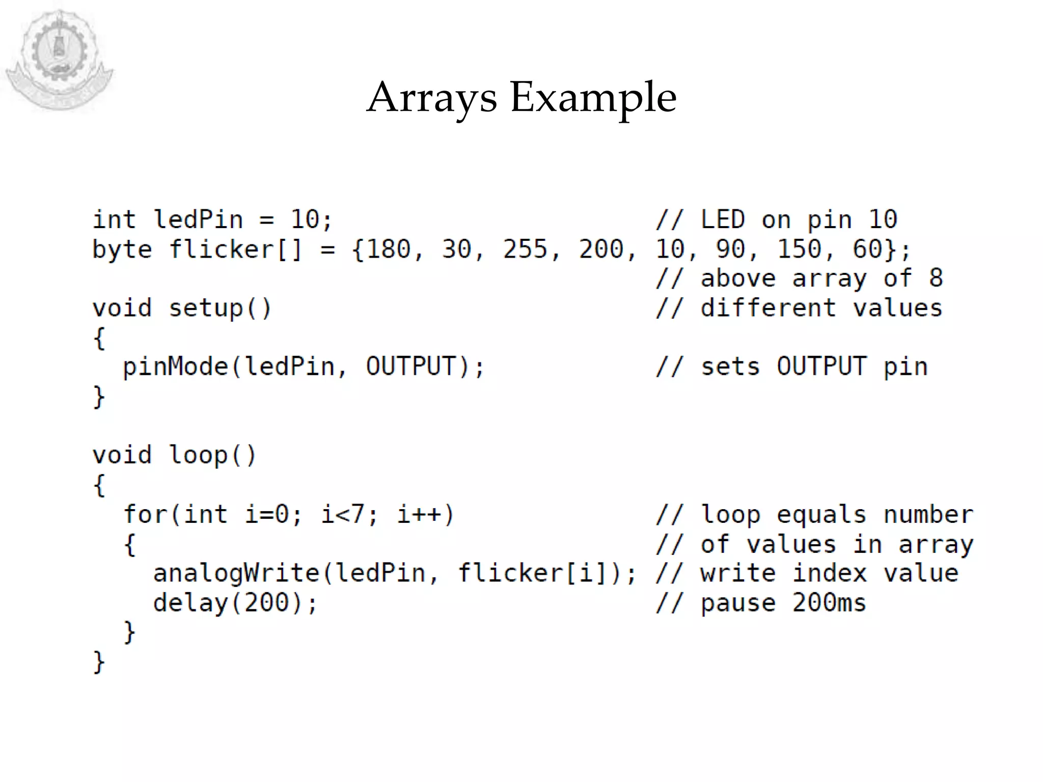
• Collection of values
• Arrays are zero indexed (First pos – 0)
int myArray[ ]={value1, value2...};
int arr[3];
array[3]=10;
x=array[3];
Arrays Example
Operators
• Arithmetic (+, -, *, /)
• Compound assignment (++,--,+= etc)
• Comparison (==,!=,<,>,<= etc)
• Logical (&&, ||, !)
Constants
• Boolean – TRUE (any value 1,2,-34)/FALSE (0)
• High/Low – Define pin levels, reading/writing digital pins
– HIGH – 1, ON, 5 volts
– LOW – 0, OFF, 0 volts
– Example: digitalWrite(13,HIGH);
• Input/Output – To define pin mode
– pinMode(13, OUTPUT);
Control Structures
• if , if-else, if else if else
• for (init; cond; expr)
• while(cond)
• do-while(cond)
pinMode(pin, mode)
• Configure the specified pin (INPUT/OUTPUT)
– pinMode(pin, OUTPUT);
• Arduino digital pins default to inputs
• 20KΩ pullup resistors accessed – Atmega chip
• Pins config as OUTPUT, provide 40mA – LED
• Not enough for relays, motors
Read - Write
• digitalRead(pin)
– Reads the pin value (High/low/0-13)
– Value=digitalRead(pin);
• digitalWrite()
– Turns on/off a pin
– digitalWrite(pin, HIGH);
Example
Read - Write
• analogRead(pin)
– Reads the pin(0-5) value (0-1023)
– Value=analogRead(pin);
• analogWrite()
– Pseudo-analog value using h/w enabled pulse width
modulation (PWM)
– analogWrite(pin, HIGH);
Other functions
• delay( ) – pauses your program
– delay(1000); //waits for one second
• millis( ) – returns no. of milliseconds
(long)
– Value=millis( );
• min(x,y) – returns minimum value
• max(x,y) – returns maximum value
Other functions
• randomSeed(seed) – sets the starting point
• random(max) – from 0 to max
• random(min, max) – from min to max
• Serial.begin(rate) – open the serial port and sets the baud rate
for serial data transmission
• Serial.println(data) – prints data to the serial port
7
Vibration /Knock (Piezo) Sensor
Program for display the value obtained from knock sensor:
const int knockSensor = A0; // connected to analog pin 0
int sensorReading = 0; // to store the value from the sensor pin
void setup( ) {
Serial.begin(9600); // use the serial port
}
void loop( ) {
sensorReading = analogRead(knockSensor);
Serial.println(sensorReading);
delay(50);
}
Program to turn on the LED based on the value obtained from sensor:
const int ledPin = 13; // led connected to digital pin 13
const int knockSensor = A0; // the piezo is connected to analog pin 0
const int threshold = 100; // threshold value to decide
int sensorReading = 0; // to store the value read from the sensor pin
int ledState = LOW; // to store the last LED status
void setup( ) {
pinMode(ledPin, OUTPUT); // declare the ledPin as as OUTPUT
Serial.begin(9600); // use the serial port
}
void loop( ) {
sensorReading = analogRead(knockSensor);
if (sensorReading >= threshold) {
ledState = !ledState;
digitalWrite(ledPin, ledState);
Serial.println("Knock!");
}
delay(100);
}
Accelerometer (ADXL3xx)
Program to display the x,y,z values obtained from accelerometer:
const int groundpin = 18;
const int powerpin = 19;
const int xpin = A3;
const int ypin = A2;
const int zpin = A1;
void setup( ) {
Serial.begin(9600);
pinMode(groundpin, OUTPUT);
pinMode(powerpin, OUTPUT);
digitalWrite(groundpin, LOW);
digitalWrite(powerpin, HIGH); }
void loop( ) {
Serial.print(analogRead(xpin)); // print the sensor values
Serial.print("t");
Serial.print(analogRead(ypin));
Serial.print("t");
Serial.print(analogRead(zpin));
Serial.println();
delay(100); }
Accelerometer (Memsic 2125)
Program to display the x,y values obtained from accelerometer:
const int xPin = 2; // X output of the accelerometer
const int yPin = 3; // Y output of the accelerometer
void setup( ) {
Serial.begin(9600);
pinMode(xPin, INPUT);
pinMode(yPin, INPUT); }
void loop( ) {
int pulseX, pulseY;
int accelerationX, accelerationY;
pulseX = pulseIn(xPin, HIGH); // read pulse from x- and y-axes in 1 second
pulseY = pulseIn(yPin, HIGH); //pulse width in micro sec
accelerationX = ((pulseX / 10) - 500) * 8; //convert pulse width into acceleration
accelerationY = ((pulseY / 10) - 500) * 8; // It is in milli-g
Serial.print(accelerationX);
Serial.print("t");
Serial.print(accelerationY);
Serial.println();
delay(100); }
Ultrasonic (SEN136B5B) - Ping
Program to display the values obtained from ultrasonic sensor (ping):
const int pingPin = 7;
void setup( ) { Serial.begin(9600); }
void loop( ) {
long duration, inches, cm;
pinMode(pingPin, OUTPUT);
digitalWrite(pingPin, LOW);
delayMicroseconds(2);
digitalWrite(pingPin, HIGH);
delayMicroseconds(5);
digitalWrite(pingPin, LOW);
pinMode(pingPin, INPUT);
duration = pulseIn(pingPin, HIGH);
inches = microsecondsToInches(duration);
cm = microsecondsToCentimeters(duration);
Serial.print(inches); Serial.print("in, "); Serial.print(cm); Serial.print("cm");
Serial.println( );
delay(100); }
long microsecondsToInches(long microseconds) { return microseconds / 74 / 2; }
long microsecondsToCentimeters(long microseconds) { return microseconds / 29 / 2; }
Bluetooth Shield
Program for control the LED pin through Bluetooth & Mobile App:
char data = 0; //Variable for storing received data
void setup( ) {
Serial.begin(9600); //Sets the baud for serial data transmission
pinMode(13,OUTPUT); //Sets digital pin 13 as output pin
}
void loop( ) {
if(Serial.available( ) > 0) // Send only when you receive data:
{ data = Serial.read( ); //Read the incoming data & store into
Serial.print(data); //Print Value inside data in Serial
Serial.print("n");
if(data == '1‘)
digitalWrite(13, HIGH);
else if (data ==‘0’)
digitalWrite(13, LOW);
}
}
Mobile App Steps
• Download the “LED Controller App” from Amazon.com
• Pair your device with HC 05 Bluetooth module
1) Turn ON HC 05 Bluetooth module
2) Scan for available device
3) Pair to HC 05 by entering default password 1234 OR 0000
• Install LED application on your android device
• Open the Application
• Press paired devices
• Select your Bluetooth module from the list (HC 05)
• After connecting successfully,
– Press ON button to turn on LED
– Press OFF button to turn off LED
USB – Communication (Keyboard)
Program for display the message through Arduino USB connection with PC
#include “Keyboard.h"
const int buttonPin = 4; // input pin for pushbutton
int previousButtonState = HIGH; // for checking the state of a pushButton
int counter = 0; // button push counter
void setup( ) {
pinMode(buttonPin, INPUT); // make the pushButton pin an input
Keyboard.begin( ); // initialize control over the keyboard
}
void loop( ) {
int buttonState = digitalRead(buttonPin); // read the pushbutton
if ((buttonState != previousButtonState) && (buttonState == HIGH)) {
counter++;
Keyboard.print("You pressed the button ");
Keyboard.print(counter);
Keyboard.println(" times.");
}
previousButtonState = buttonState;
}
Steps need to follow
• Upload the code into Arduino and unplug the USB cable
• Open a text editor and put the text cursor at in the typing
area.
• Connect the board to your computer through USB again
• Press the button to write in the document.
Problems
• Change the intensity of the led light based on the
vibration/sound value obtained.
• Glow the LEDs with respect to the movement of the
accelerometer
• Glow the LED, if an object is identified during the ping
using ultrasonic sensor
• Display the alphabets one by one when the push button
pressed using Arduino
• Perform Arithmetic operation using push button with
Arduino
• Control the Fan using Bluetooth
• Control the buzzer alarm using Bluetooth
References
• Brian W.Evans, Arduino Programming Note book, e-
book with CC-ANS licence, 2007.
• https://www.arduino.cc/en/Tutorial/Knock
• https://www.arduino.cc/en/Tutorial/Memsic2125
• https://www.arduino.cc/en/Tutorial/ADXL3xx
• https://www.arduino.cc/en/Tutorial/Ping
• https://create.arduino.cc/projecthub
• https://www.arduino.cc/en/Tutorial/KeyboardMessage
Thanks

Arduino Programming

  • 1.
    ARDUINO PROGRAMMING Dr.P.Karthikeyan Associate Professor Departmentof Information Technology Thiagarajar College of Engineering Madurai - 625 015
  • 3.
    Structure • void setup() { statements } //preparation – Declaration of variables – First function to run – run only once – To set pinmode or initialize serial communication – It must be present for the program to run
  • 4.
    Structure • void loop() { statements } //execution – Code to be executed continuously – Reading inputs – Triggering outputs – Allowing program to change, respond and control the arduino board
  • 5.
    Structure • Custom Functions/User-defined functions – To perform repetitive tasks – General format/ syntax – Example function
  • 6.
    Variables • Naming andstoring a numerical value • Variable with condition • Variable declaration and scope
  • 7.
    Data types • Byte– 8 bits (0-255) • Integer – 16 bits (32767 to –32768) – roll over • Long – 32 bits (2,147,483,647 to -2,147,483,647) • Float – 32 bits (3.4028235E+38 to -3.40...)
  • 8.
    Arrays • Collection ofvalues • Arrays are zero indexed (First pos – 0) int myArray[ ]={value1, value2...}; int arr[3]; array[3]=10; x=array[3];
  • 9.
  • 10.
    Operators • Arithmetic (+,-, *, /) • Compound assignment (++,--,+= etc) • Comparison (==,!=,<,>,<= etc) • Logical (&&, ||, !)
  • 11.
    Constants • Boolean –TRUE (any value 1,2,-34)/FALSE (0) • High/Low – Define pin levels, reading/writing digital pins – HIGH – 1, ON, 5 volts – LOW – 0, OFF, 0 volts – Example: digitalWrite(13,HIGH); • Input/Output – To define pin mode – pinMode(13, OUTPUT);
  • 12.
    Control Structures • if, if-else, if else if else • for (init; cond; expr) • while(cond) • do-while(cond)
  • 13.
    pinMode(pin, mode) • Configurethe specified pin (INPUT/OUTPUT) – pinMode(pin, OUTPUT); • Arduino digital pins default to inputs • 20KΩ pullup resistors accessed – Atmega chip • Pins config as OUTPUT, provide 40mA – LED • Not enough for relays, motors
  • 14.
    Read - Write •digitalRead(pin) – Reads the pin value (High/low/0-13) – Value=digitalRead(pin); • digitalWrite() – Turns on/off a pin – digitalWrite(pin, HIGH);
  • 15.
  • 16.
    Read - Write •analogRead(pin) – Reads the pin(0-5) value (0-1023) – Value=analogRead(pin); • analogWrite() – Pseudo-analog value using h/w enabled pulse width modulation (PWM) – analogWrite(pin, HIGH);
  • 17.
    Other functions • delay() – pauses your program – delay(1000); //waits for one second • millis( ) – returns no. of milliseconds (long) – Value=millis( ); • min(x,y) – returns minimum value • max(x,y) – returns maximum value
  • 18.
    Other functions • randomSeed(seed)– sets the starting point • random(max) – from 0 to max • random(min, max) – from min to max • Serial.begin(rate) – open the serial port and sets the baud rate for serial data transmission • Serial.println(data) – prints data to the serial port
  • 21.
  • 22.
  • 23.
    Program for displaythe value obtained from knock sensor: const int knockSensor = A0; // connected to analog pin 0 int sensorReading = 0; // to store the value from the sensor pin void setup( ) { Serial.begin(9600); // use the serial port } void loop( ) { sensorReading = analogRead(knockSensor); Serial.println(sensorReading); delay(50); }
  • 24.
    Program to turnon the LED based on the value obtained from sensor: const int ledPin = 13; // led connected to digital pin 13 const int knockSensor = A0; // the piezo is connected to analog pin 0 const int threshold = 100; // threshold value to decide int sensorReading = 0; // to store the value read from the sensor pin int ledState = LOW; // to store the last LED status void setup( ) { pinMode(ledPin, OUTPUT); // declare the ledPin as as OUTPUT Serial.begin(9600); // use the serial port } void loop( ) { sensorReading = analogRead(knockSensor); if (sensorReading >= threshold) { ledState = !ledState; digitalWrite(ledPin, ledState); Serial.println("Knock!"); } delay(100); }
  • 25.
  • 26.
    Program to displaythe x,y,z values obtained from accelerometer: const int groundpin = 18; const int powerpin = 19; const int xpin = A3; const int ypin = A2; const int zpin = A1; void setup( ) { Serial.begin(9600); pinMode(groundpin, OUTPUT); pinMode(powerpin, OUTPUT); digitalWrite(groundpin, LOW); digitalWrite(powerpin, HIGH); } void loop( ) { Serial.print(analogRead(xpin)); // print the sensor values Serial.print("t"); Serial.print(analogRead(ypin)); Serial.print("t"); Serial.print(analogRead(zpin)); Serial.println(); delay(100); }
  • 27.
  • 29.
    Program to displaythe x,y values obtained from accelerometer: const int xPin = 2; // X output of the accelerometer const int yPin = 3; // Y output of the accelerometer void setup( ) { Serial.begin(9600); pinMode(xPin, INPUT); pinMode(yPin, INPUT); } void loop( ) { int pulseX, pulseY; int accelerationX, accelerationY; pulseX = pulseIn(xPin, HIGH); // read pulse from x- and y-axes in 1 second pulseY = pulseIn(yPin, HIGH); //pulse width in micro sec accelerationX = ((pulseX / 10) - 500) * 8; //convert pulse width into acceleration accelerationY = ((pulseY / 10) - 500) * 8; // It is in milli-g Serial.print(accelerationX); Serial.print("t"); Serial.print(accelerationY); Serial.println(); delay(100); }
  • 30.
  • 31.
    Program to displaythe values obtained from ultrasonic sensor (ping): const int pingPin = 7; void setup( ) { Serial.begin(9600); } void loop( ) { long duration, inches, cm; pinMode(pingPin, OUTPUT); digitalWrite(pingPin, LOW); delayMicroseconds(2); digitalWrite(pingPin, HIGH); delayMicroseconds(5); digitalWrite(pingPin, LOW); pinMode(pingPin, INPUT); duration = pulseIn(pingPin, HIGH); inches = microsecondsToInches(duration); cm = microsecondsToCentimeters(duration); Serial.print(inches); Serial.print("in, "); Serial.print(cm); Serial.print("cm"); Serial.println( ); delay(100); } long microsecondsToInches(long microseconds) { return microseconds / 74 / 2; } long microsecondsToCentimeters(long microseconds) { return microseconds / 29 / 2; }
  • 32.
  • 33.
    Program for controlthe LED pin through Bluetooth & Mobile App: char data = 0; //Variable for storing received data void setup( ) { Serial.begin(9600); //Sets the baud for serial data transmission pinMode(13,OUTPUT); //Sets digital pin 13 as output pin } void loop( ) { if(Serial.available( ) > 0) // Send only when you receive data: { data = Serial.read( ); //Read the incoming data & store into Serial.print(data); //Print Value inside data in Serial Serial.print("n"); if(data == '1‘) digitalWrite(13, HIGH); else if (data ==‘0’) digitalWrite(13, LOW); } }
  • 34.
    Mobile App Steps •Download the “LED Controller App” from Amazon.com • Pair your device with HC 05 Bluetooth module 1) Turn ON HC 05 Bluetooth module 2) Scan for available device 3) Pair to HC 05 by entering default password 1234 OR 0000 • Install LED application on your android device • Open the Application • Press paired devices • Select your Bluetooth module from the list (HC 05) • After connecting successfully, – Press ON button to turn on LED – Press OFF button to turn off LED
  • 35.
  • 36.
    Program for displaythe message through Arduino USB connection with PC #include “Keyboard.h" const int buttonPin = 4; // input pin for pushbutton int previousButtonState = HIGH; // for checking the state of a pushButton int counter = 0; // button push counter void setup( ) { pinMode(buttonPin, INPUT); // make the pushButton pin an input Keyboard.begin( ); // initialize control over the keyboard } void loop( ) { int buttonState = digitalRead(buttonPin); // read the pushbutton if ((buttonState != previousButtonState) && (buttonState == HIGH)) { counter++; Keyboard.print("You pressed the button "); Keyboard.print(counter); Keyboard.println(" times."); } previousButtonState = buttonState; }
  • 37.
    Steps need tofollow • Upload the code into Arduino and unplug the USB cable • Open a text editor and put the text cursor at in the typing area. • Connect the board to your computer through USB again • Press the button to write in the document.
  • 38.
    Problems • Change theintensity of the led light based on the vibration/sound value obtained. • Glow the LEDs with respect to the movement of the accelerometer • Glow the LED, if an object is identified during the ping using ultrasonic sensor • Display the alphabets one by one when the push button pressed using Arduino • Perform Arithmetic operation using push button with Arduino • Control the Fan using Bluetooth • Control the buzzer alarm using Bluetooth
  • 39.
    References • Brian W.Evans,Arduino Programming Note book, e- book with CC-ANS licence, 2007. • https://www.arduino.cc/en/Tutorial/Knock • https://www.arduino.cc/en/Tutorial/Memsic2125 • https://www.arduino.cc/en/Tutorial/ADXL3xx • https://www.arduino.cc/en/Tutorial/Ping • https://create.arduino.cc/projecthub • https://www.arduino.cc/en/Tutorial/KeyboardMessage
  • 40.