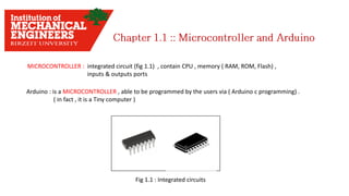
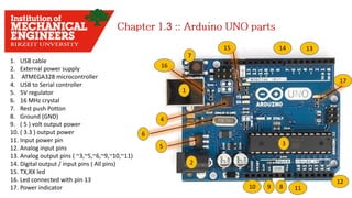
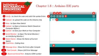
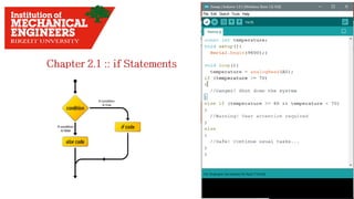
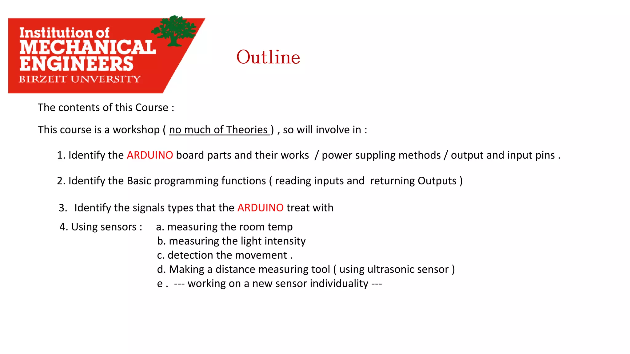
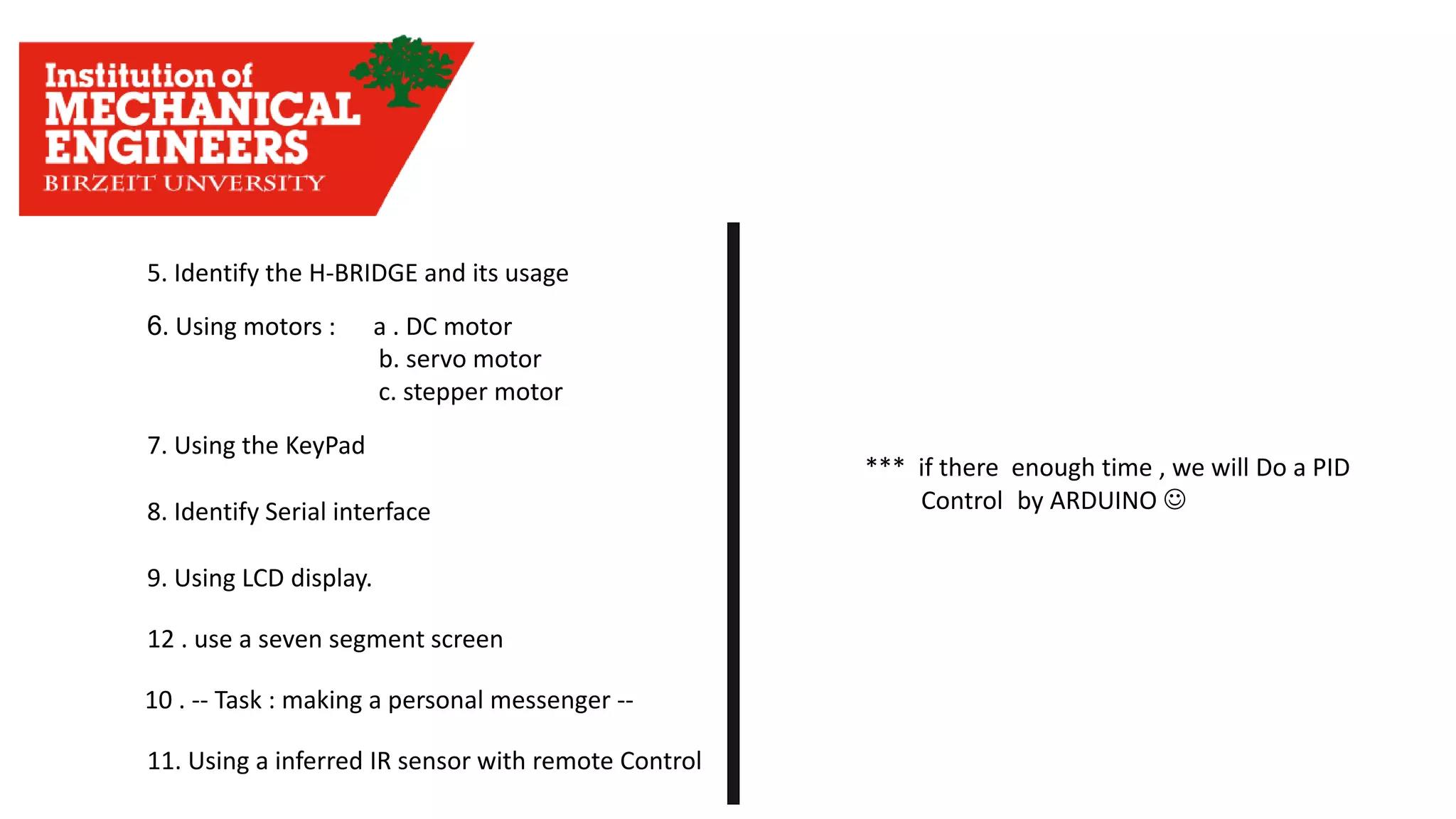
1. This document provides an overview of the contents to be covered in an Arduino and programming course.
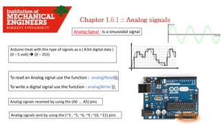
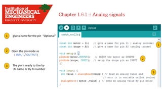
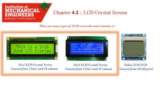
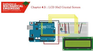
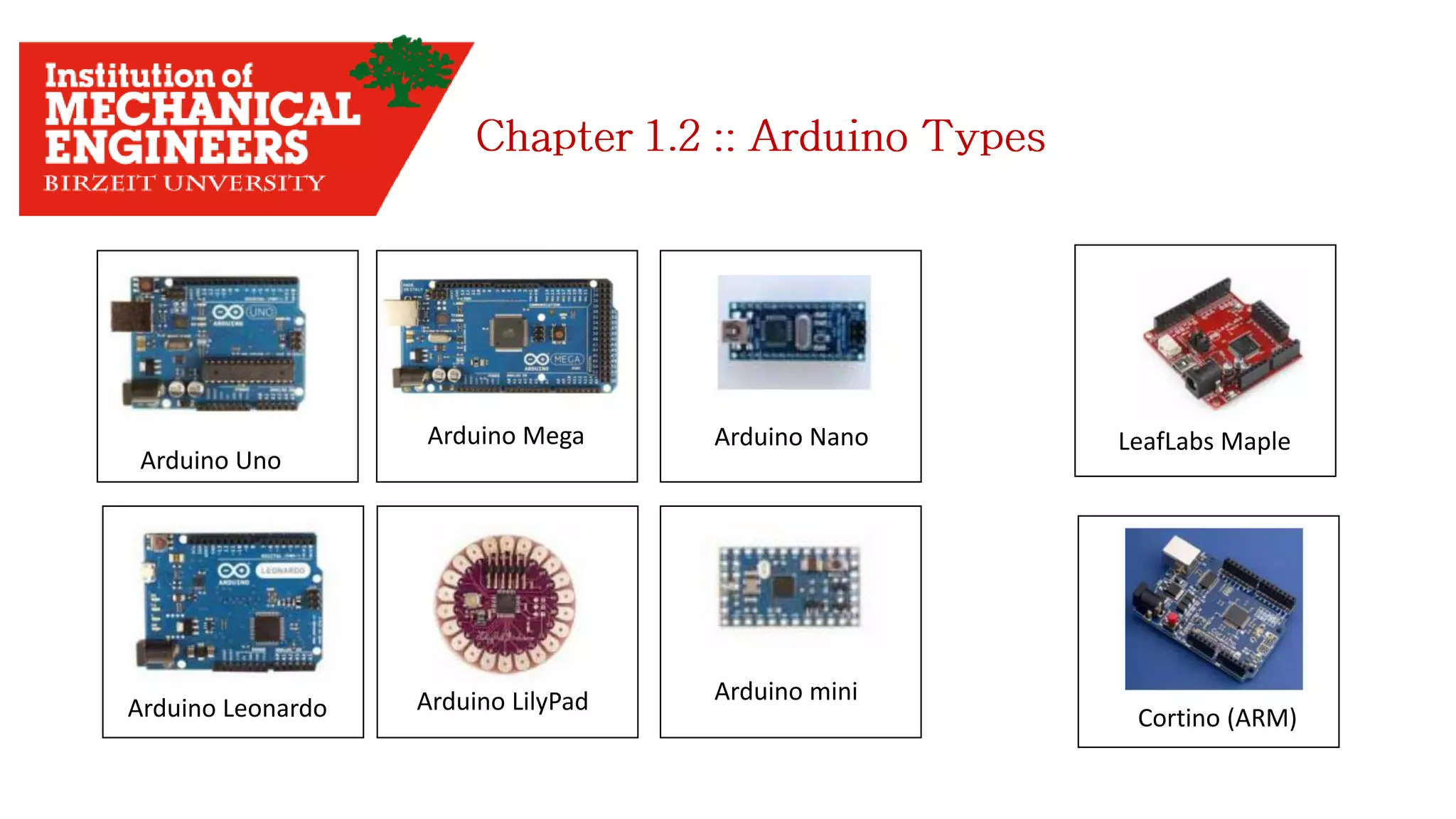
2. The course will cover identifying Arduino board components, basic programming functions, signal types, using various sensors and motors, serial communication, and LCD displays.
3. Additional topics may include PID control and using a seven segment display, depending on available time.


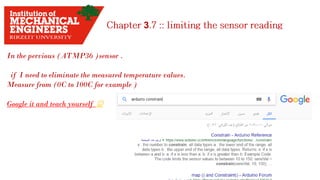
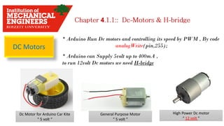
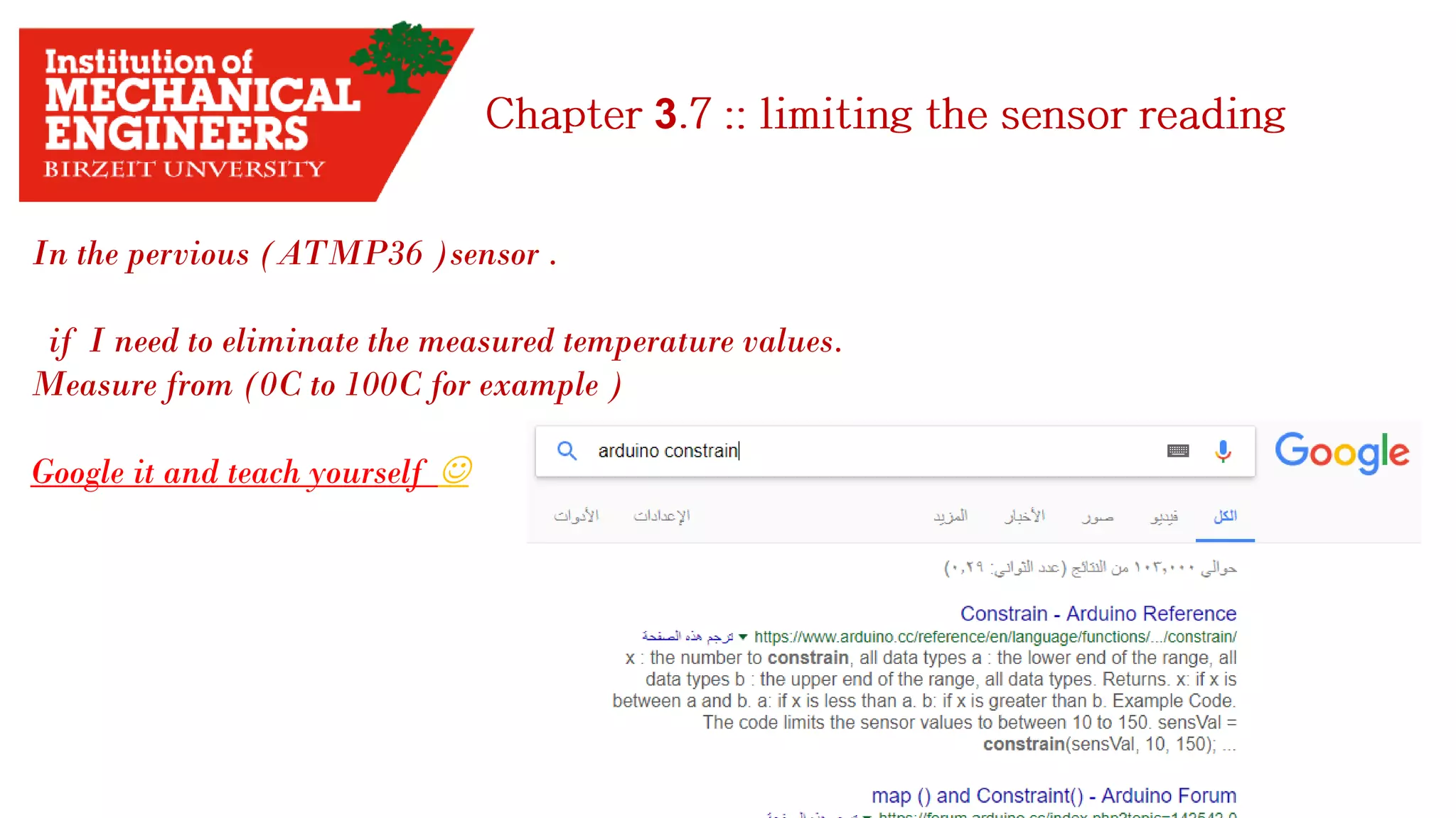
![3
Tow Thing you have start with:
1. Get the data sheet
2. find the range of measuring.
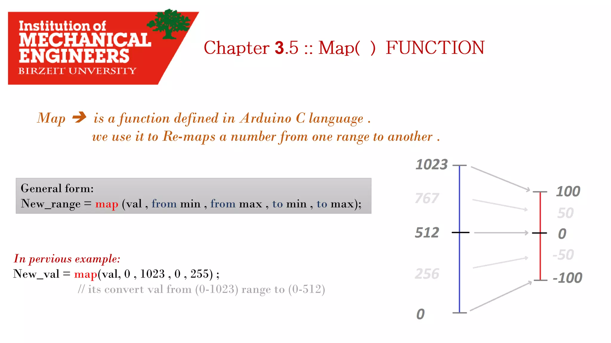
3. Use the map() function.
Example:
I have to measure the temperature in my room.
The sensor needed is TMP36 sensor. How can I start with ?!
1. Search in google for [TMP36 sensor].
2. Find the voltage range.
3. Find the measuring range.
4. Try to know how dose the sensor work.](https://image.slidesharecdn.com/arduino-imeche-bzu-180402200653/85/Starting-with-Arduino-32-320.jpg)

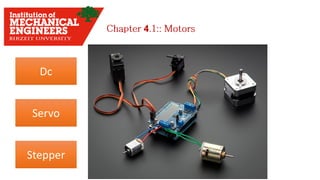
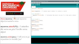
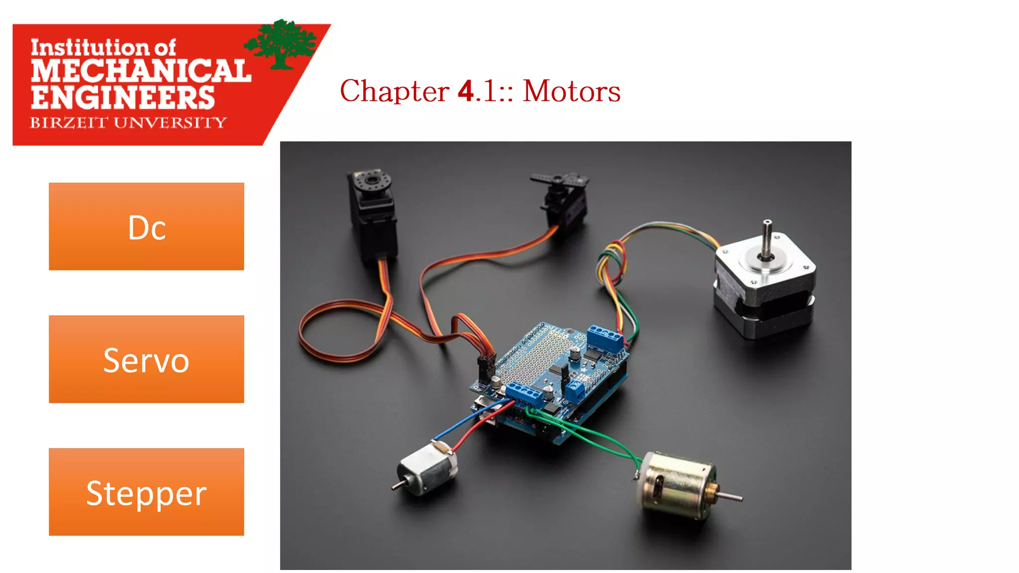
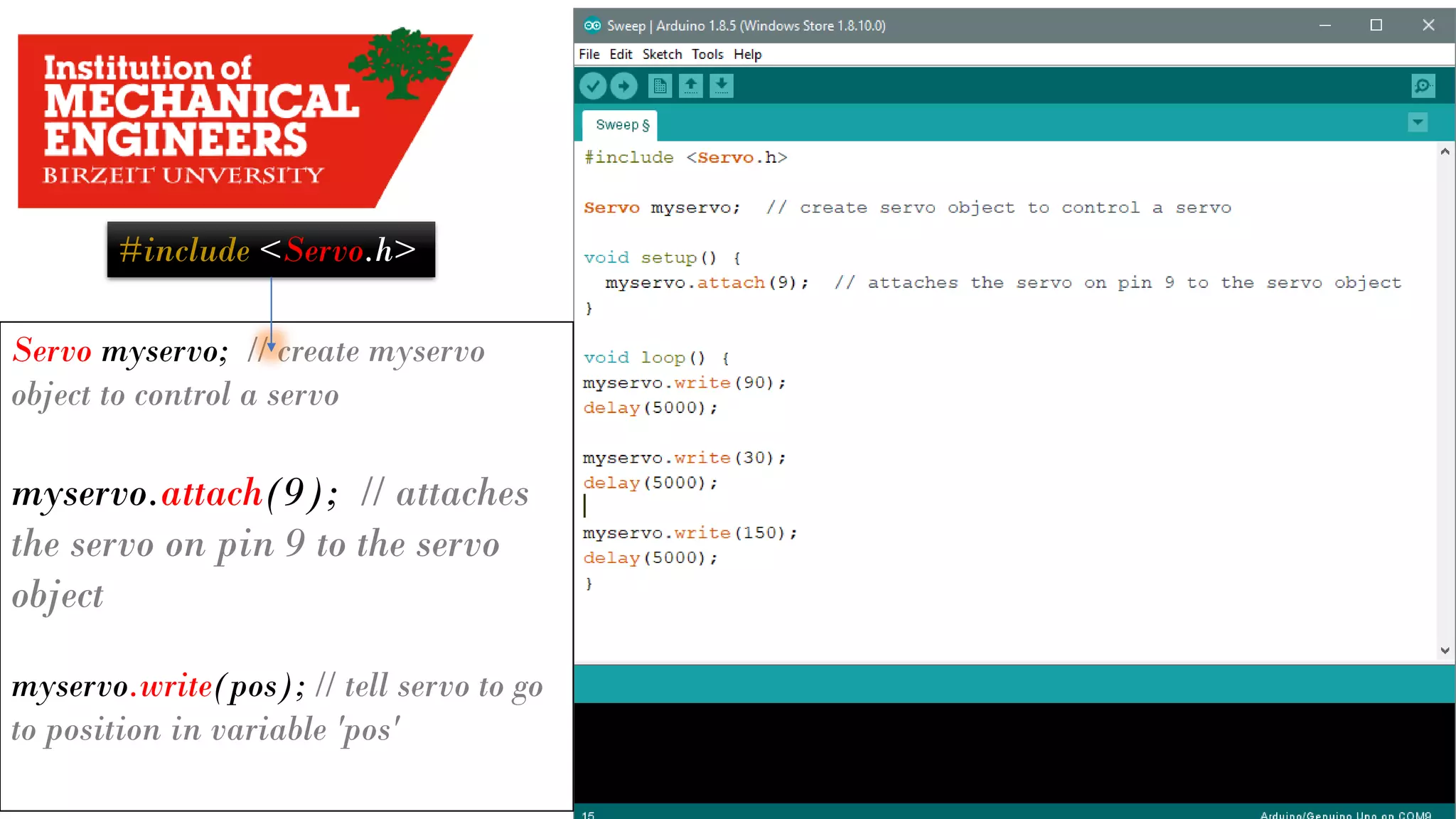
![Servo Motors
* Motor rotates with certain angles in [Degrees], i.e: 60 , 90 , 180 …
* <Servo.h> Library used to drive the Servo Motor
Micro ServoBig Black Servo
4](https://image.slidesharecdn.com/arduino-imeche-bzu-180402200653/85/Starting-with-Arduino-41-320.jpg)
![4.2
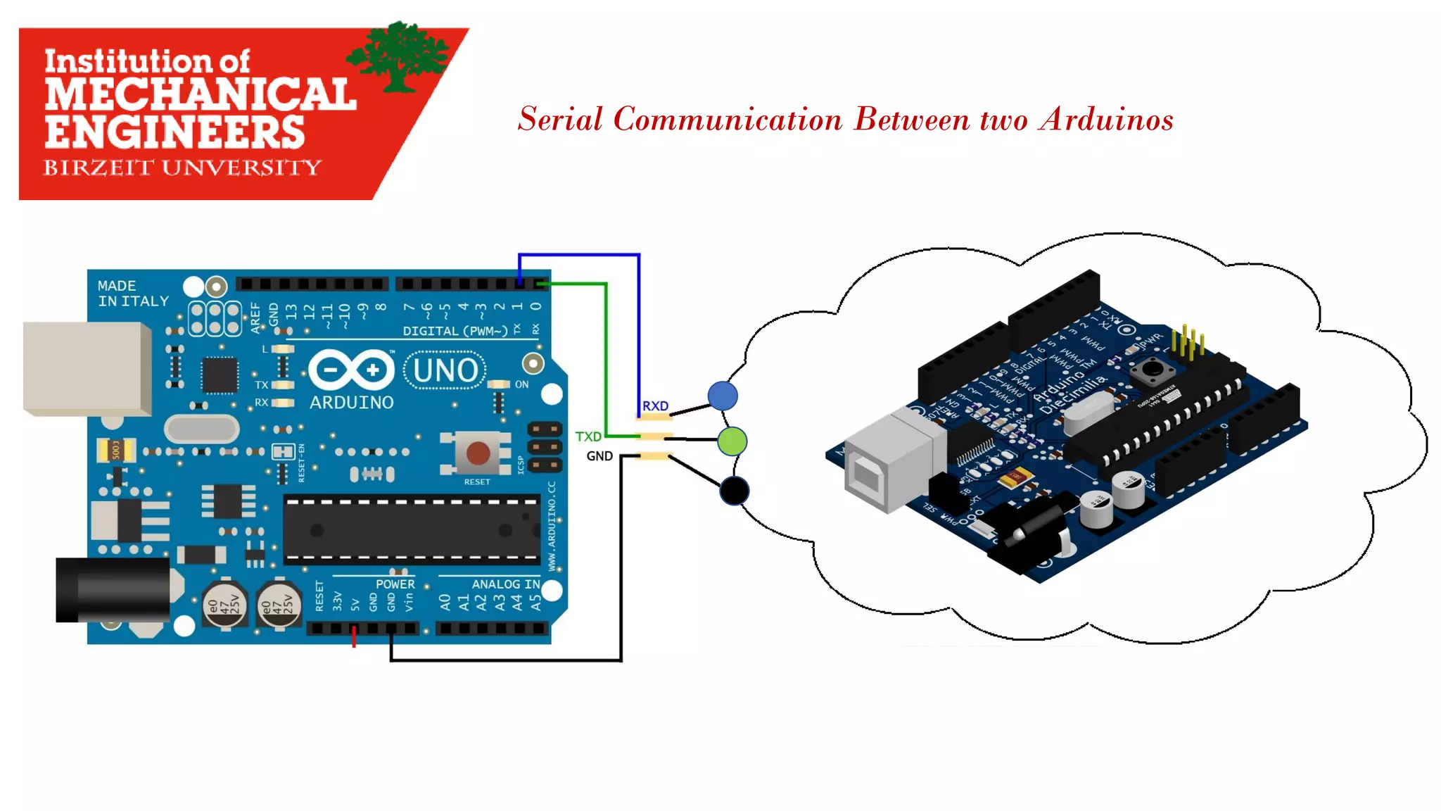
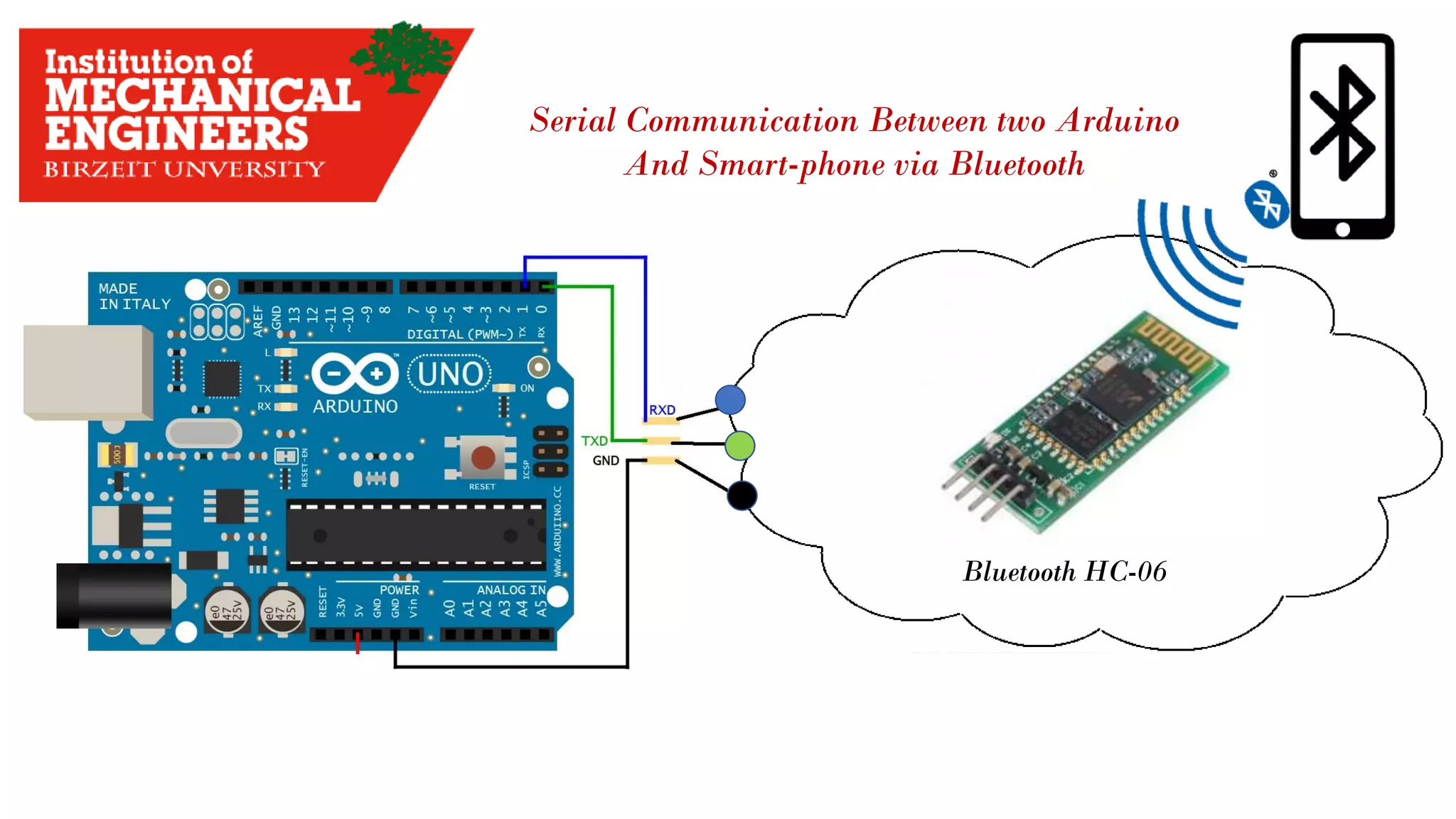
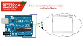
The data Transmitted and Reserved Serially
Serial Data Flow
Baud Rate : how fast data Transmitted
Expressed in [Bit Per Second]](https://image.slidesharecdn.com/arduino-imeche-bzu-180402200653/85/Starting-with-Arduino-43-320.jpg)


![3
Tow Thing you have start with:
1. Get the data sheet
2. find the range of measuring.
3. Use the map() function.
Example:
I have to measure the temperature in my room.
The sensor needed is TMP36 sensor. How can I start with ?!
1. Search in google for [TMP36 sensor].
2. Find the voltage range.
3. Find the measuring range.
4. Try to know how dose the sensor work.](https://image.slidesharecdn.com/arduino-imeche-bzu-180402200653/75/Starting-with-Arduino-32-2048.jpg)


![Servo Motors
* Motor rotates with certain angles in [Degrees], i.e: 60 , 90 , 180 …
* <Servo.h> Library used to drive the Servo Motor
Micro ServoBig Black Servo
4](https://image.slidesharecdn.com/arduino-imeche-bzu-180402200653/75/Starting-with-Arduino-41-2048.jpg)
![4.2
The data Transmitted and Reserved Serially
Serial Data Flow
Baud Rate : how fast data Transmitted
Expressed in [Bit Per Second]](https://image.slidesharecdn.com/arduino-imeche-bzu-180402200653/75/Starting-with-Arduino-43-2048.jpg)