Downloaded 528 times

![Z-BUFFER ALGORITHM:
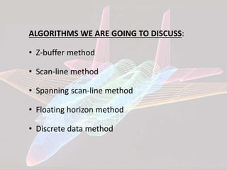
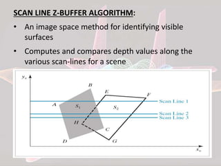
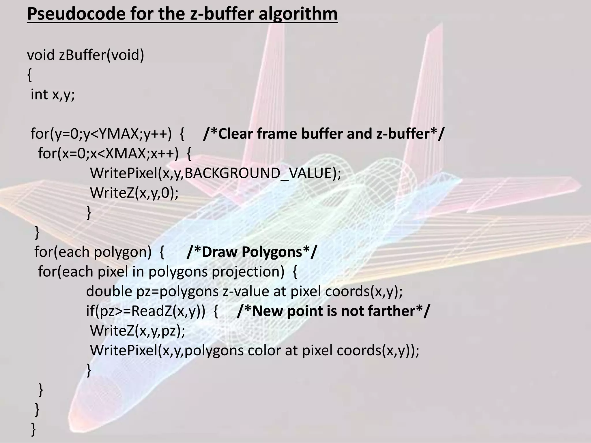
• Its an extension of Frame Buffer
• Display is always stored on Frame Buffer
• Frame Buffer stores information of each and every
pixel on the screen
• Bits (0, 1) decide that the pixel will be ON or OFF
• Z- Buffer apart from Frame buffer stores the depth
of pixel
• After analyzing the data of the overlapping
polygons, pixel closer to the eye will be updated
• Resolution of X,Y => Array[X,Y]](https://image.slidesharecdn.com/cghlrappt-150601180631-lva1-app6892/85/Computer-Graphics-Hidden-Line-Removal-Algorithm-6-320.jpg)
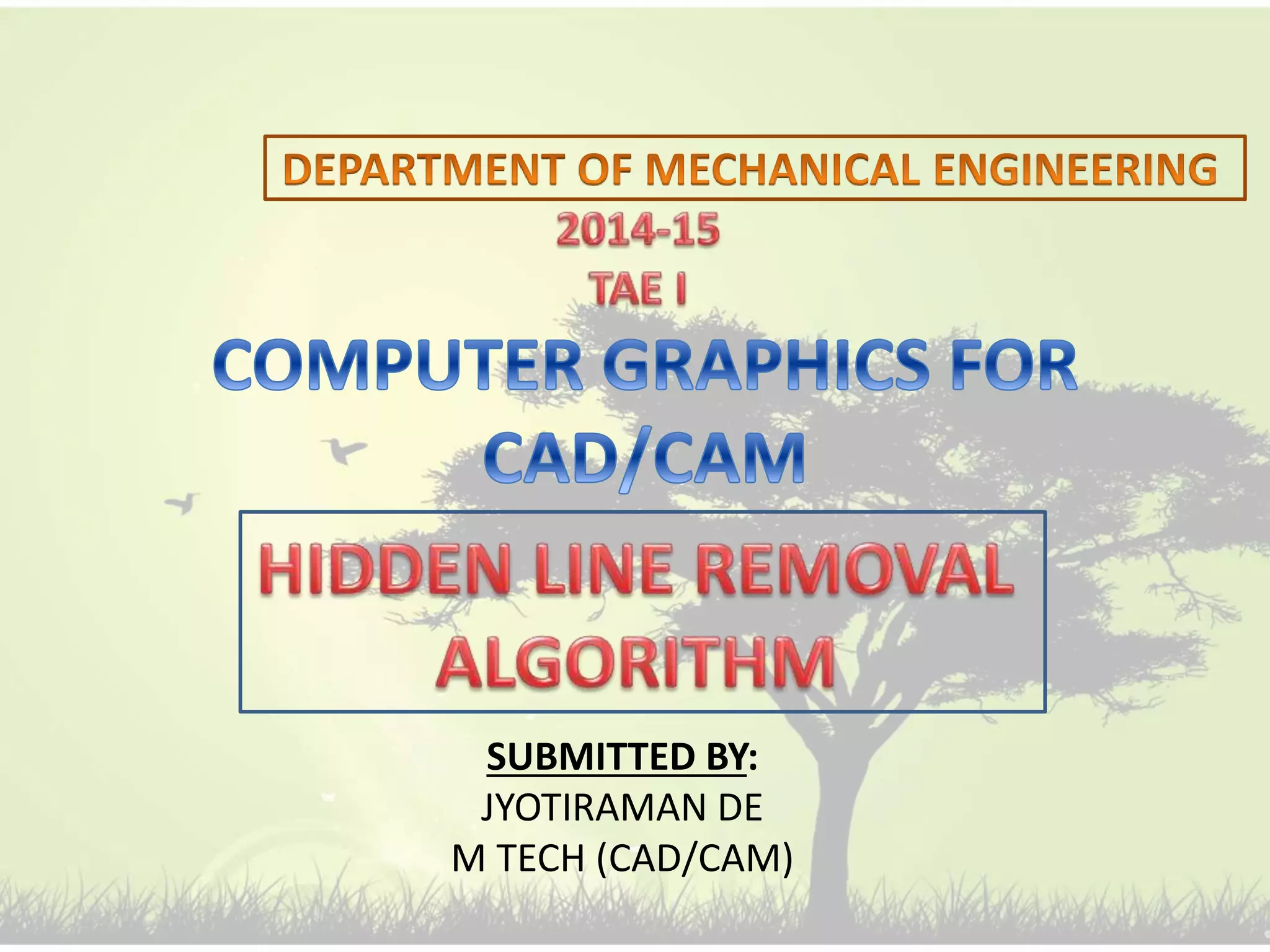
![1 2 3 4 5 6
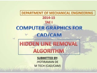
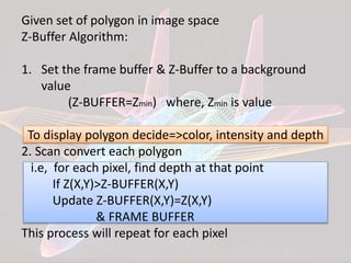
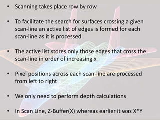
Each span at
most one
polygon shall be
displayed
• For each polygon determine the highest scan line
intersected by it
• Place the polygon in the Y-Bucket of that scan line
[YB]
• For each scan line
-Examine YB for any new polygon
-Add new polygon to APL
-Update AEL
-Divide into spans
-In each span decide which polygon shall be displayed
-Increment Y, update AEL & APL](https://image.slidesharecdn.com/cghlrappt-150601180631-lva1-app6892/85/Computer-Graphics-Hidden-Line-Removal-Algorithm-15-320.jpg)
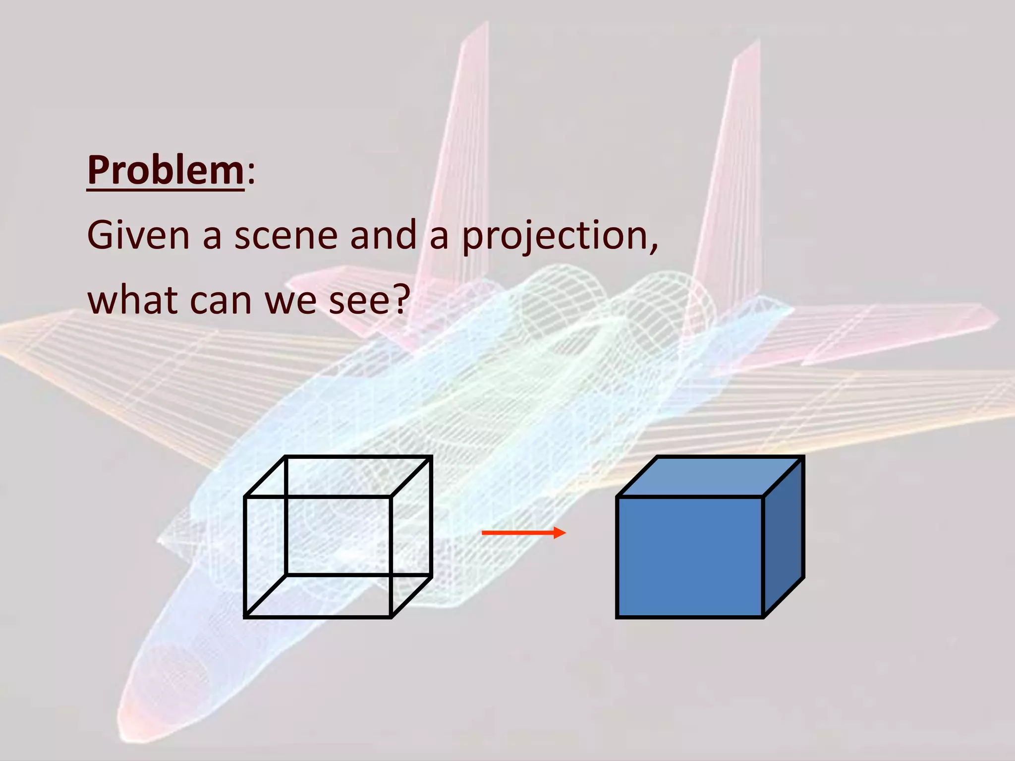
![FLOATING HORIZON ALGORITHM:
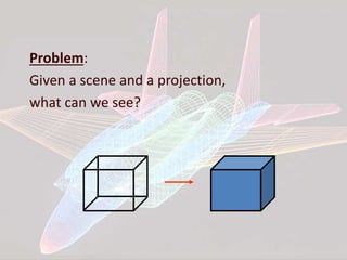
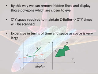
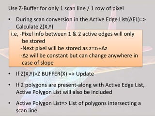
• Used for displaying surface
• Take each plane & intersection
z=constant plane and get a curve
from F(x,y)=0 f(x,y,z)=0
Array HORIZONTAL[X]=Ymax
Curve in each plane=>f(x,y)=0
y=f(x,y)
z=constant curves
Family of curves](https://image.slidesharecdn.com/cghlrappt-150601180631-lva1-app6892/85/Computer-Graphics-Hidden-Line-Removal-Algorithm-16-320.jpg)
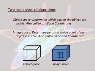
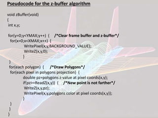
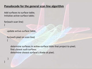
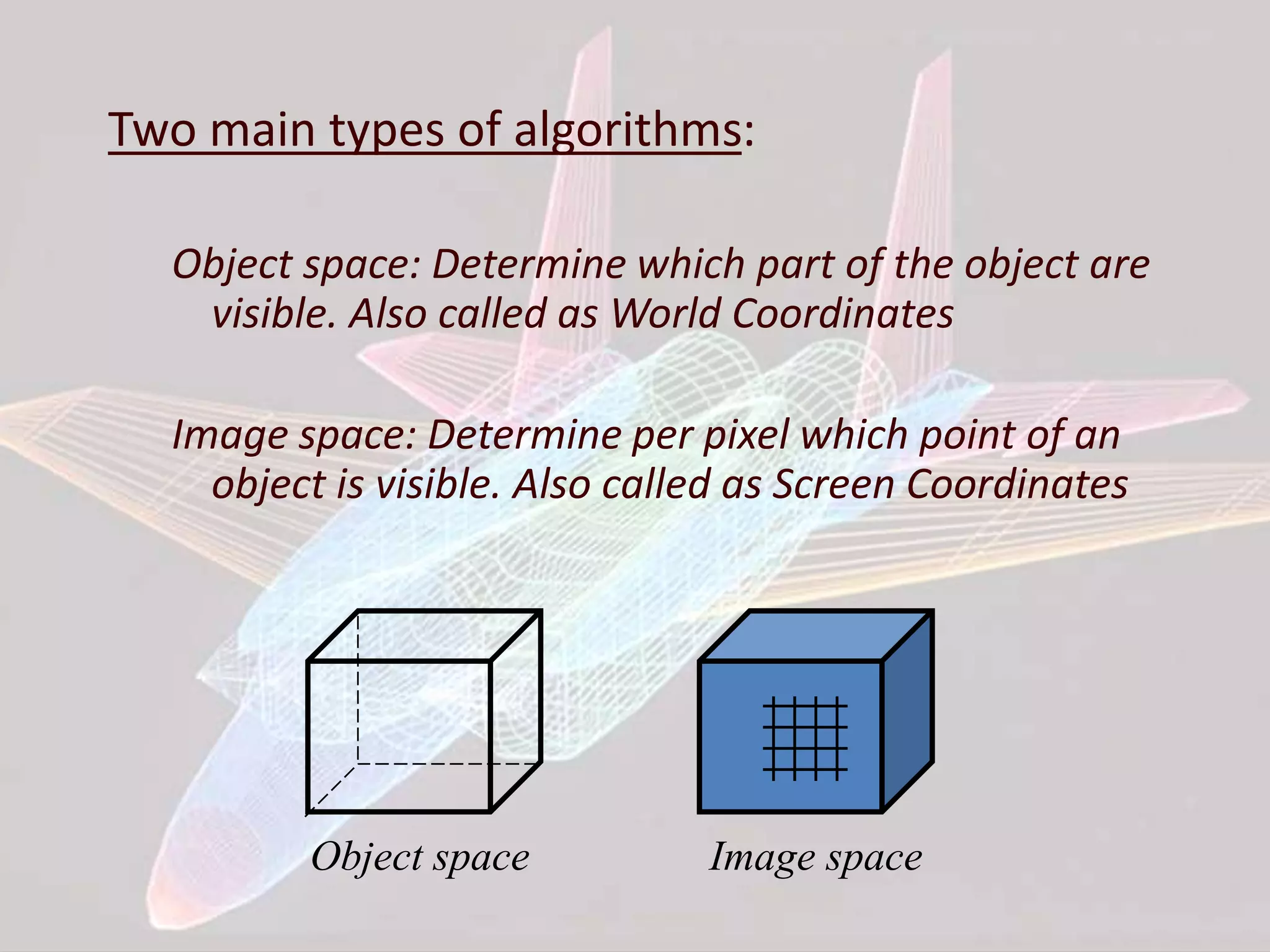
![• Maintain HORIZON[X] at each side
• While displaying next curve, it will be compared to 2
points i.e, Y(Xi) & Y(Xi+1)
• If both points are visible, then the complete curve is
visible
• Algorithm will be complex as the curve is in discrete
data form
Y(Xi) Y(Xi+1) Result
V V Curve is visible
V I Xi to Intersection -> Visible
Intersection to Xi+1 -> NOT Visible
I V Xi to Intersection -> NOT Visible
Intersection to Xi+1 -> Visible
I I NOT Visible](https://image.slidesharecdn.com/cghlrappt-150601180631-lva1-app6892/85/Computer-Graphics-Hidden-Line-Removal-Algorithm-19-320.jpg)

![Z-BUFFER ALGORITHM:
• Its an extension of Frame Buffer
• Display is always stored on Frame Buffer
• Frame Buffer stores information of each and every
pixel on the screen
• Bits (0, 1) decide that the pixel will be ON or OFF
• Z- Buffer apart from Frame buffer stores the depth
of pixel
• After analyzing the data of the overlapping
polygons, pixel closer to the eye will be updated
• Resolution of X,Y => Array[X,Y]](https://image.slidesharecdn.com/cghlrappt-150601180631-lva1-app6892/75/Computer-Graphics-Hidden-Line-Removal-Algorithm-6-2048.jpg)
![1 2 3 4 5 6
Each span at
most one
polygon shall be
displayed
• For each polygon determine the highest scan line
intersected by it
• Place the polygon in the Y-Bucket of that scan line
[YB]
• For each scan line
-Examine YB for any new polygon
-Add new polygon to APL
-Update AEL
-Divide into spans
-In each span decide which polygon shall be displayed
-Increment Y, update AEL & APL](https://image.slidesharecdn.com/cghlrappt-150601180631-lva1-app6892/75/Computer-Graphics-Hidden-Line-Removal-Algorithm-15-2048.jpg)
![FLOATING HORIZON ALGORITHM:
• Used for displaying surface
• Take each plane & intersection
z=constant plane and get a curve
from F(x,y)=0 f(x,y,z)=0
Array HORIZONTAL[X]=Ymax
Curve in each plane=>f(x,y)=0
y=f(x,y)
z=constant curves
Family of curves](https://image.slidesharecdn.com/cghlrappt-150601180631-lva1-app6892/75/Computer-Graphics-Hidden-Line-Removal-Algorithm-16-2048.jpg)
![• Maintain HORIZON[X] at each side
• While displaying next curve, it will be compared to 2
points i.e, Y(Xi) & Y(Xi+1)
• If both points are visible, then the complete curve is
visible
• Algorithm will be complex as the curve is in discrete
data form
Y(Xi) Y(Xi+1) Result
V V Curve is visible
V I Xi to Intersection -> Visible
Intersection to Xi+1 -> NOT Visible
I V Xi to Intersection -> NOT Visible
Intersection to Xi+1 -> Visible
I I NOT Visible](https://image.slidesharecdn.com/cghlrappt-150601180631-lva1-app6892/75/Computer-Graphics-Hidden-Line-Removal-Algorithm-19-2048.jpg)


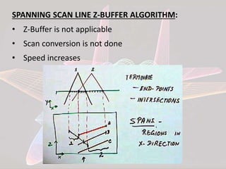
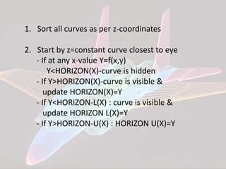
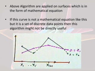
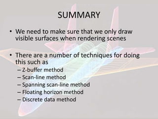
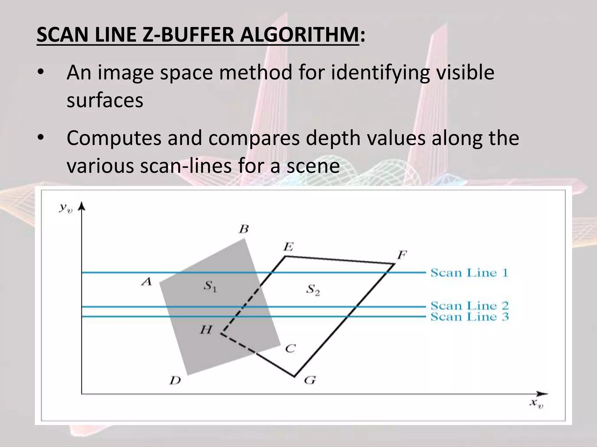
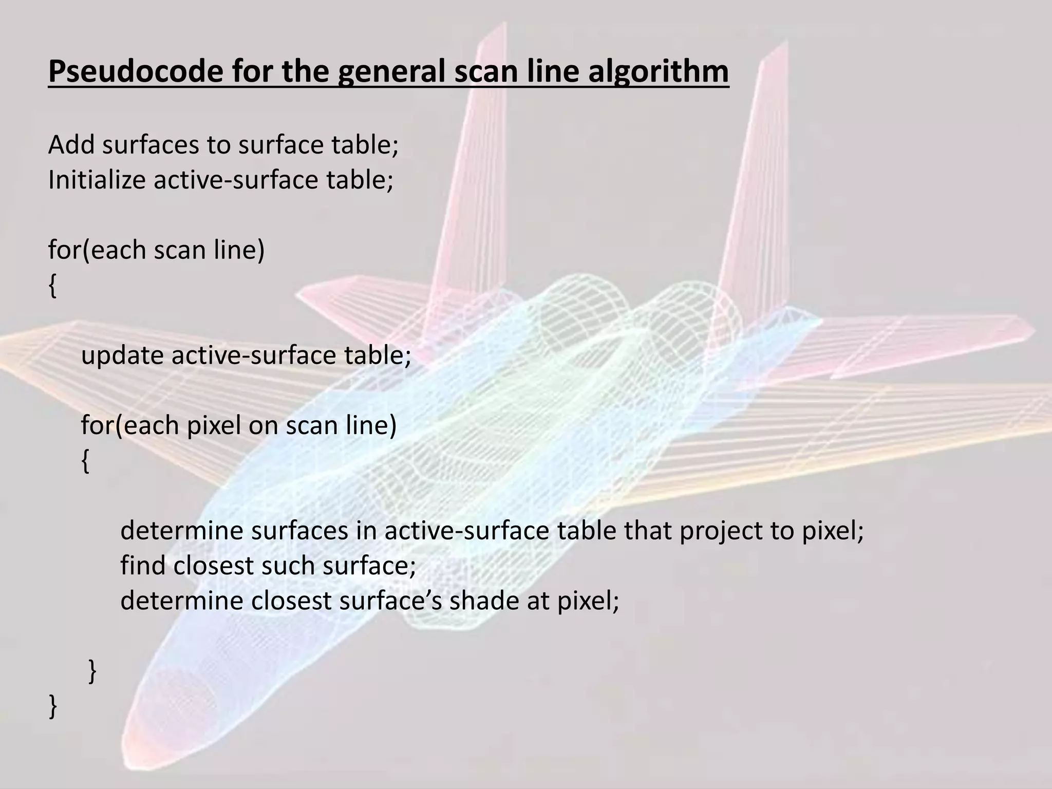
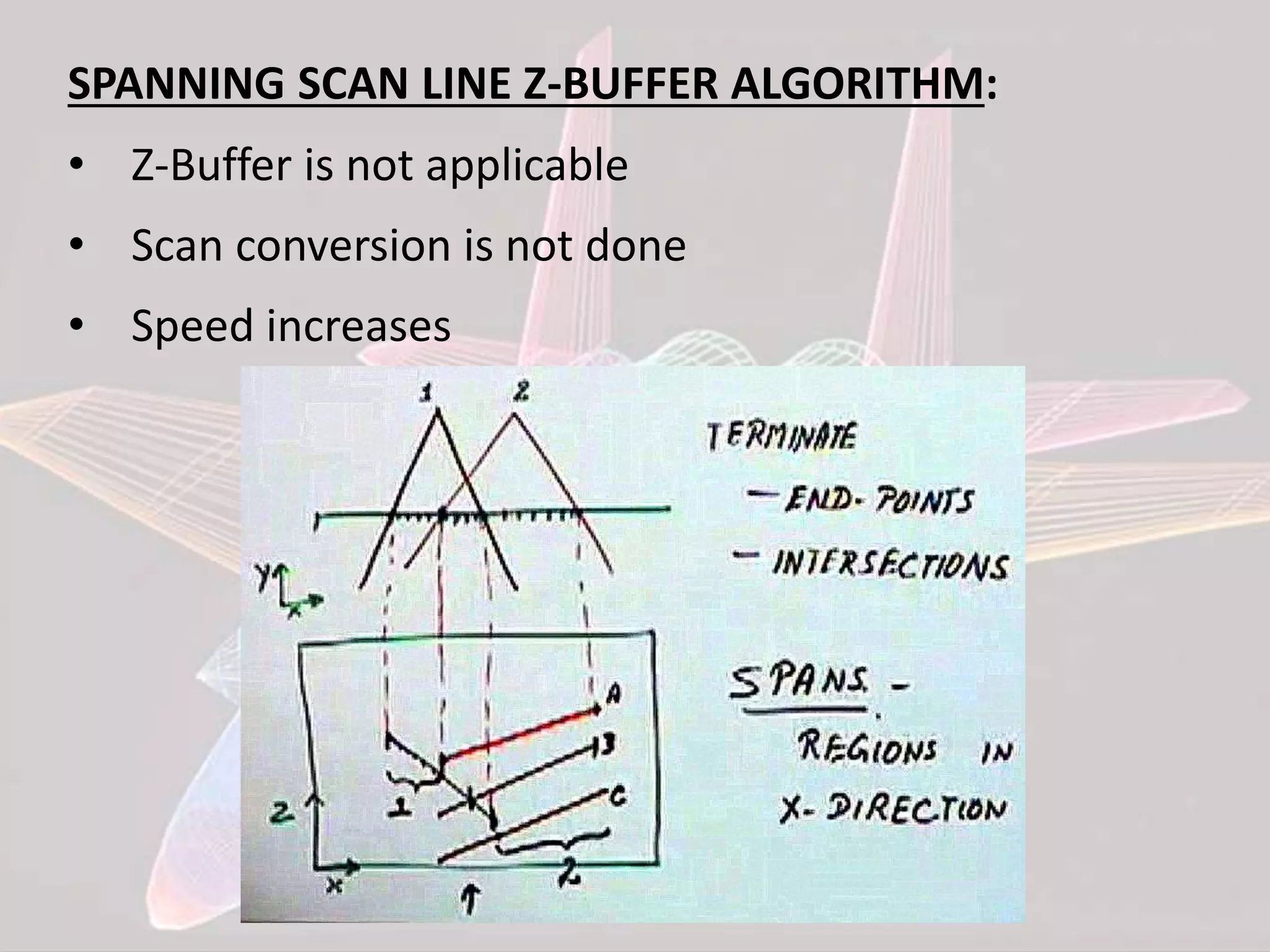
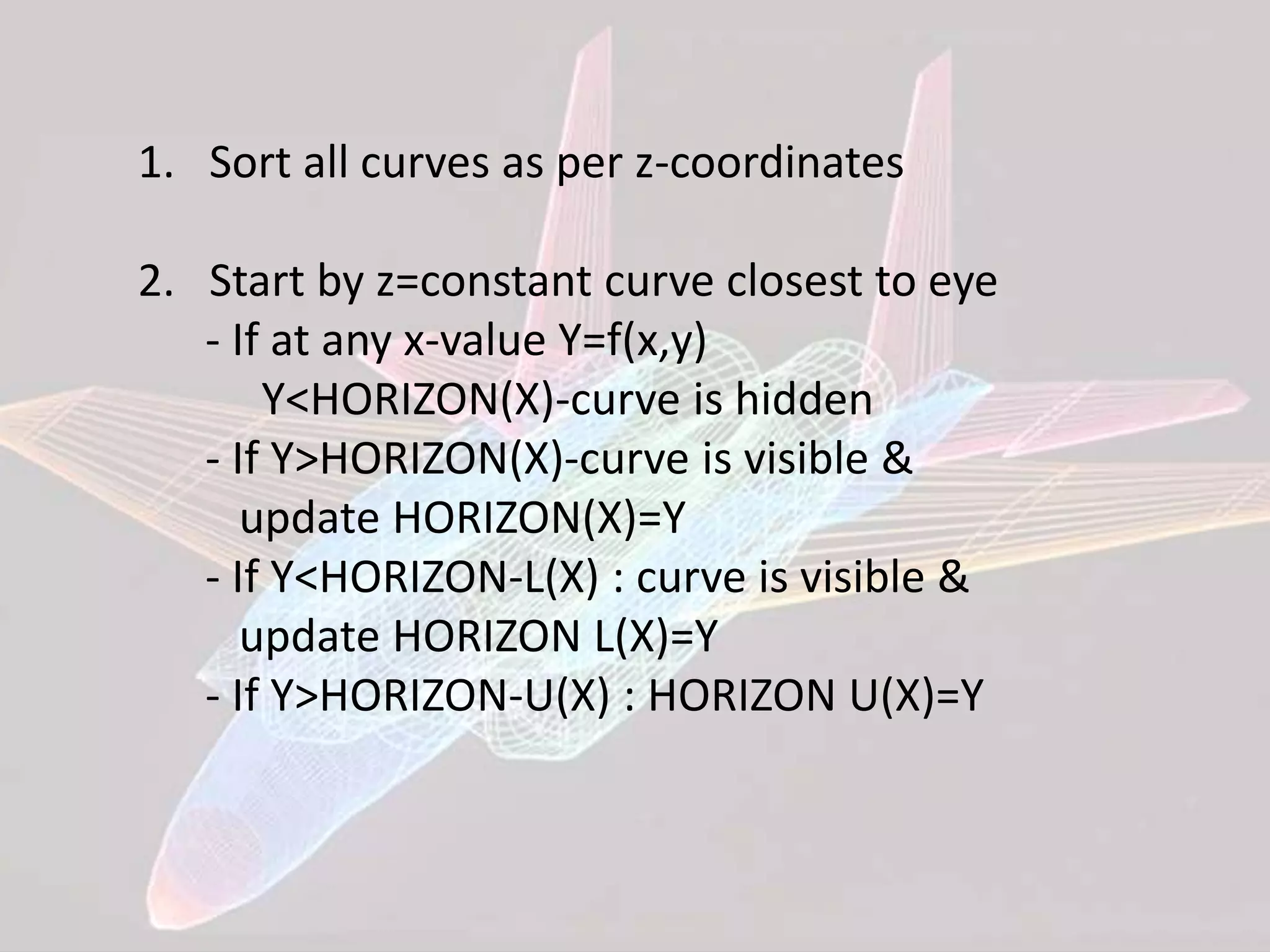
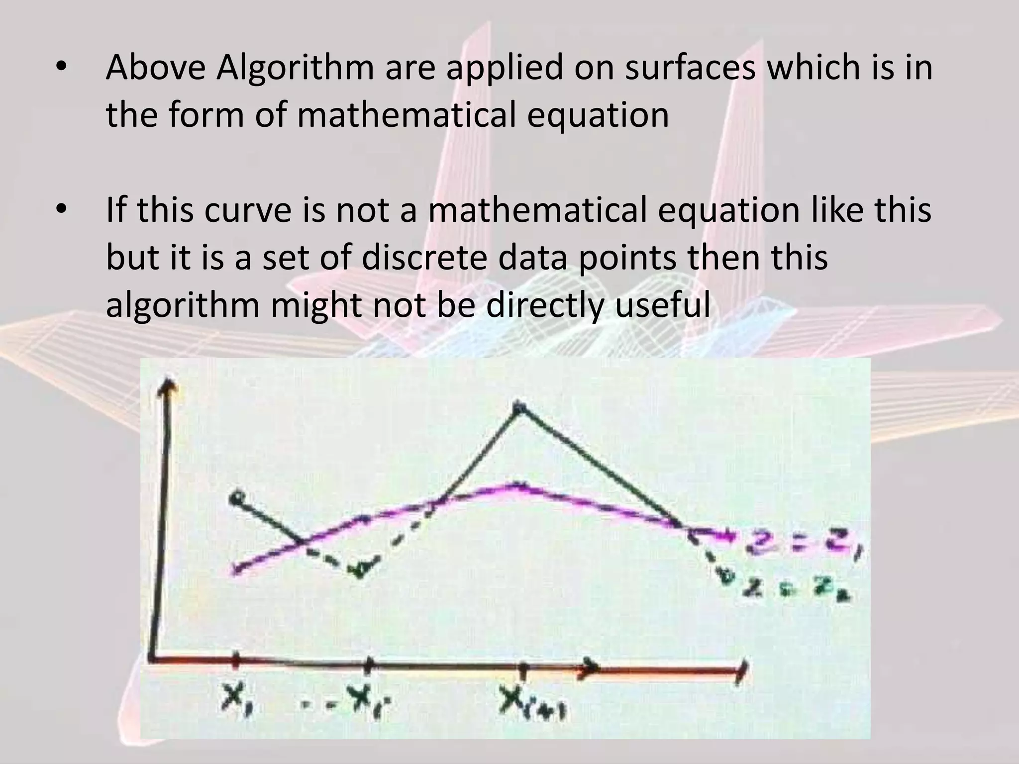
This document discusses various algorithms for hidden surface removal when rendering 3D scenes, including the z-buffer method, scan-line method, spanning scan-line method, floating horizon method, and discrete data method. The z-buffer method uses a depth buffer to track the closest surface at each pixel. The scan-line method only considers visible surfaces within each scan line. The floating horizon method finds the visible portions of curves using a horizon array. The discrete data method handles surfaces defined by discrete points rather than mathematical equations.